
Controlled Synthesis of Mesoporous Solid Polymer Electrolyte Au(Pt)NiCe/C Membrane Electrode for Electrocatalytic Hydrogenation

Abstract
1. Introduction
2. Experiments
3. Results and Discussion
3.1. XRD Analysis
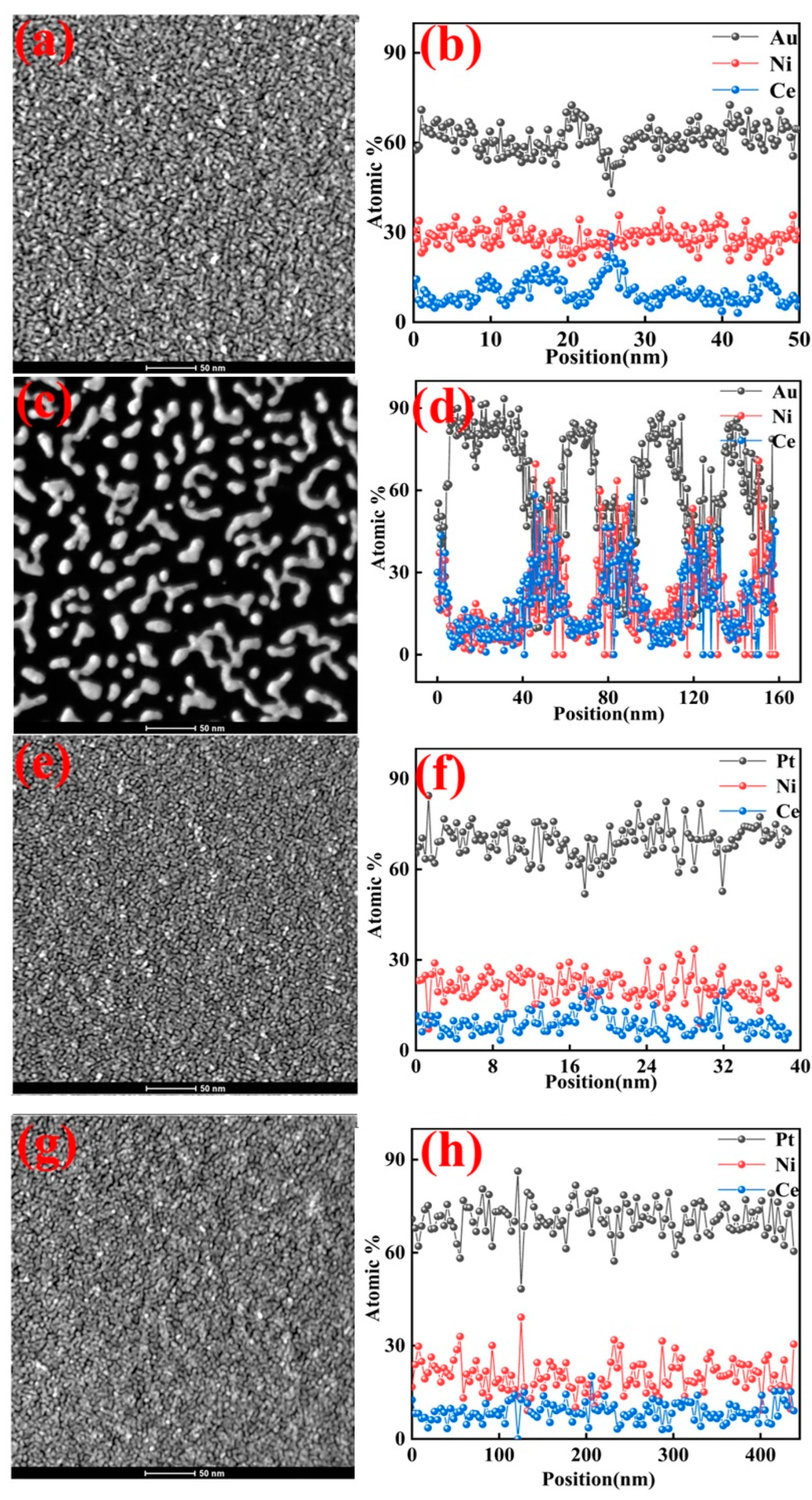
3.2. STEM and EDX Analyses
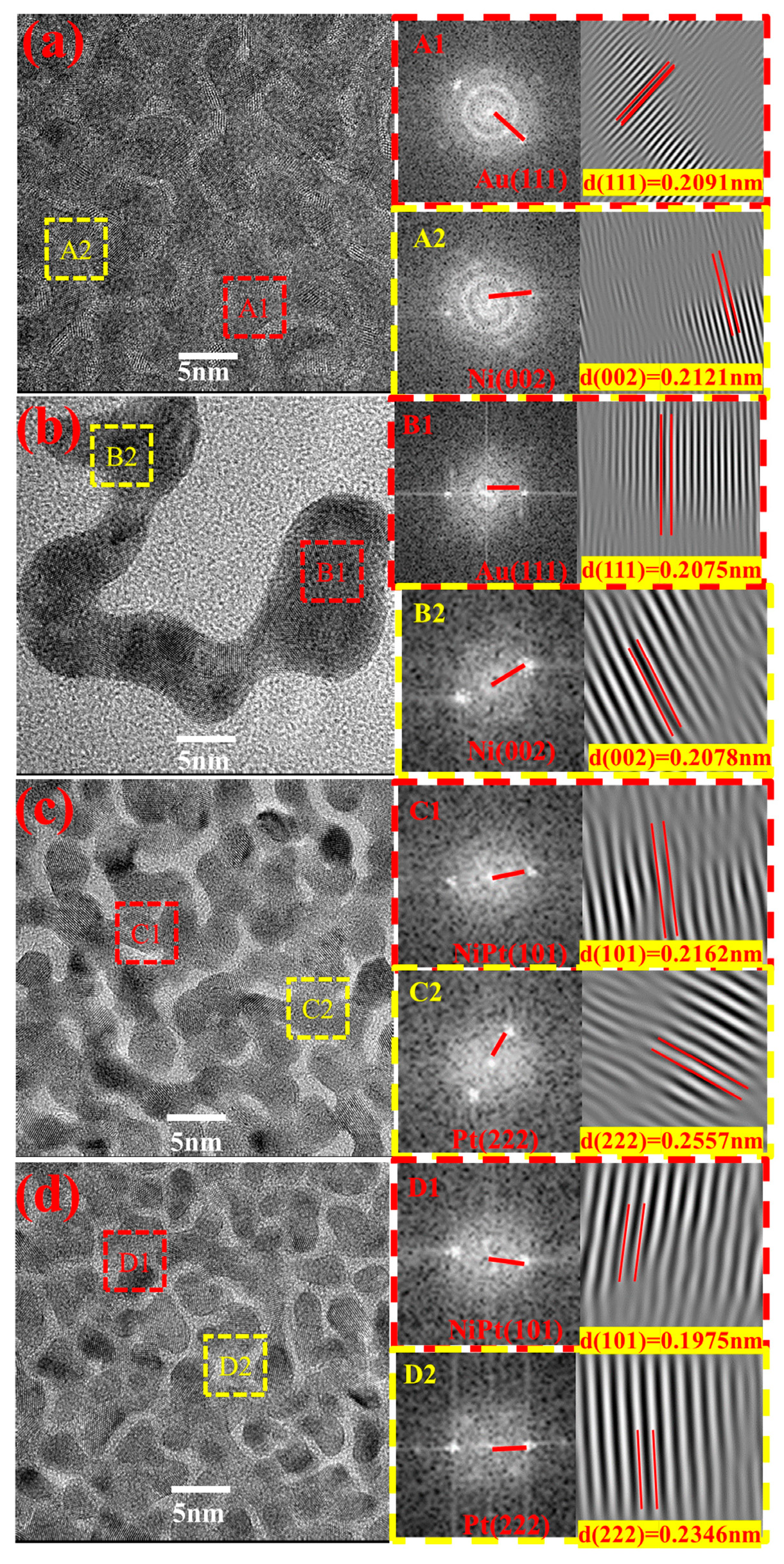
3.3. HRTEM Analysis
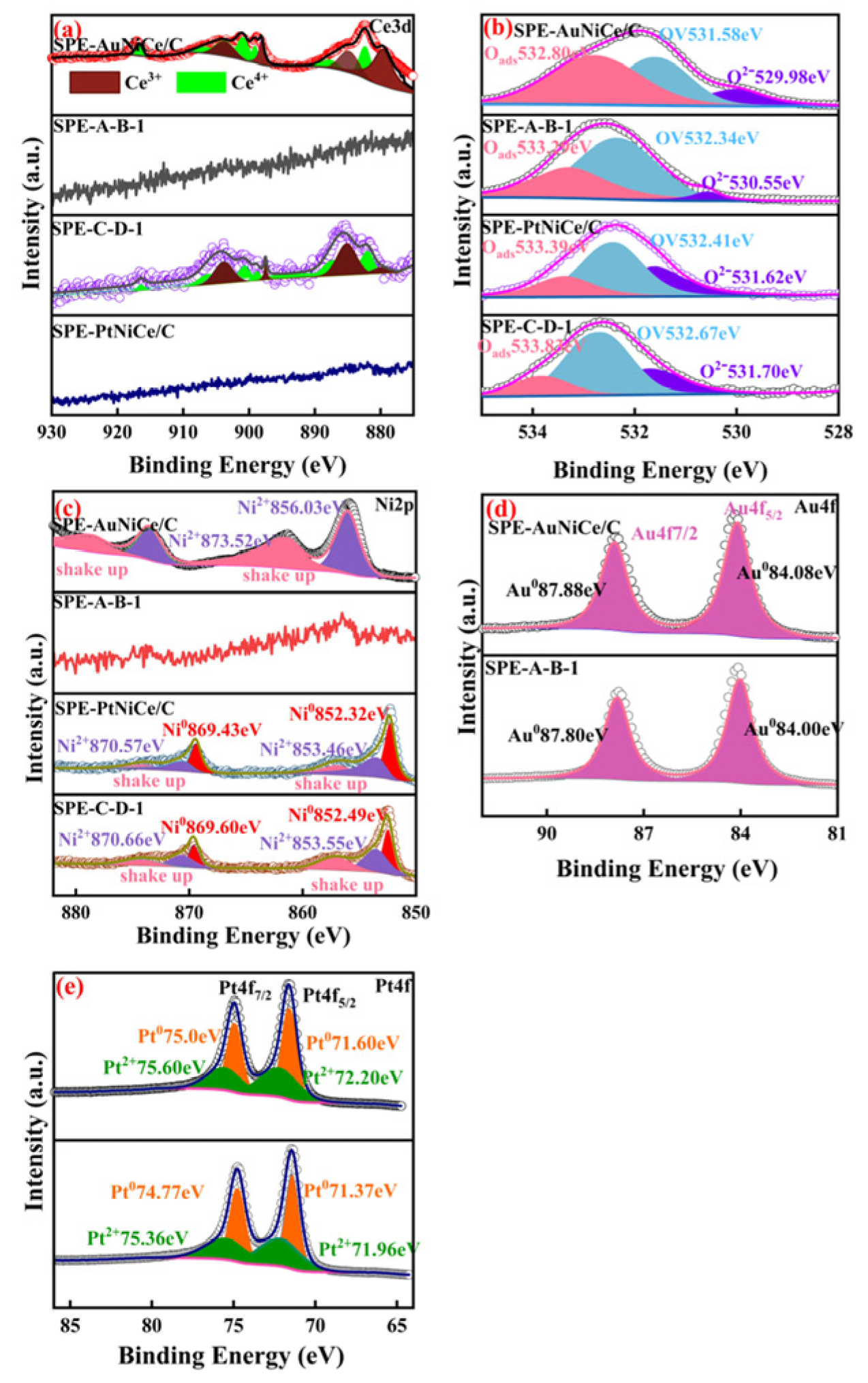
3.4. XPS Analysis
3.5. BET Analysis
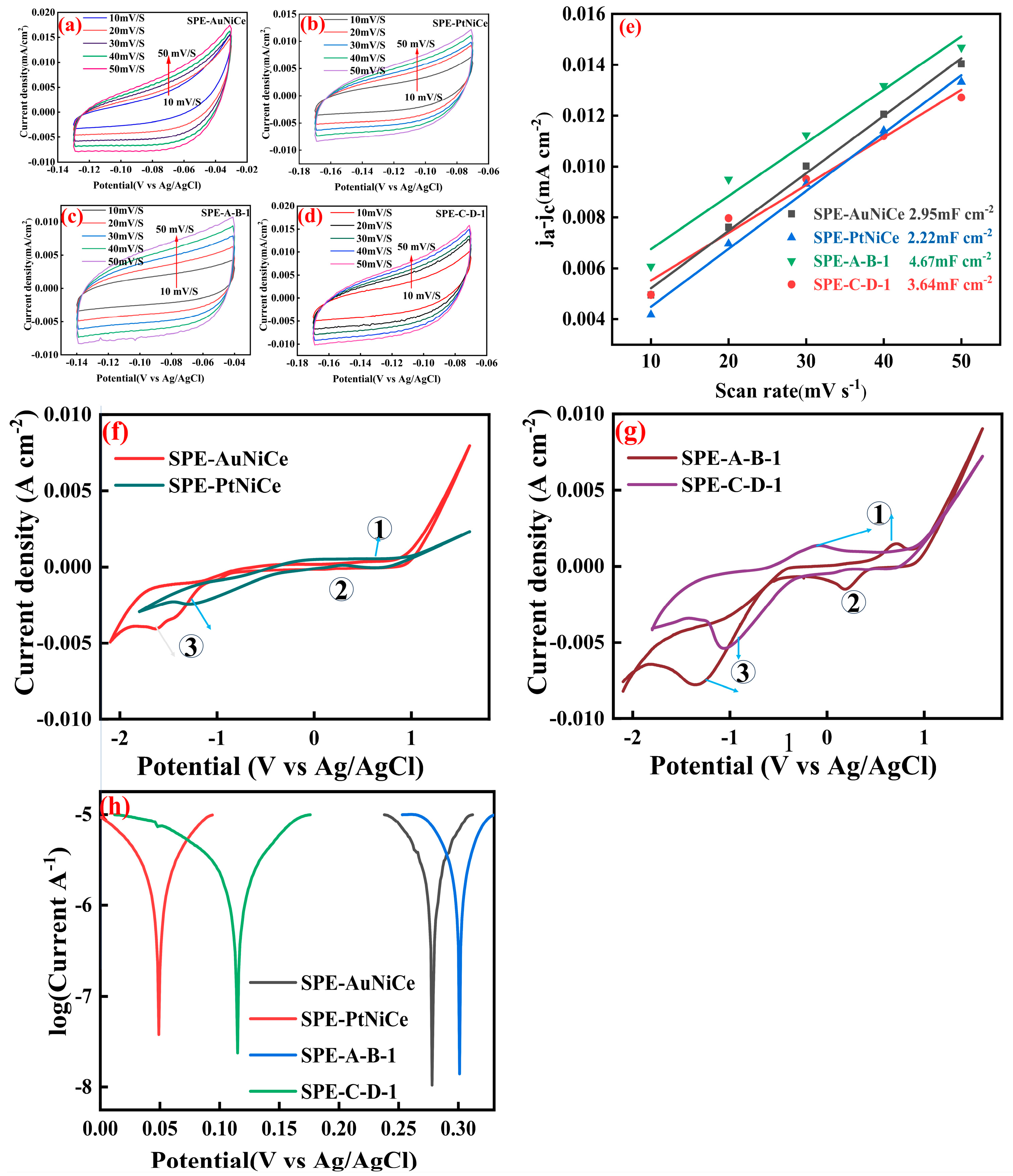
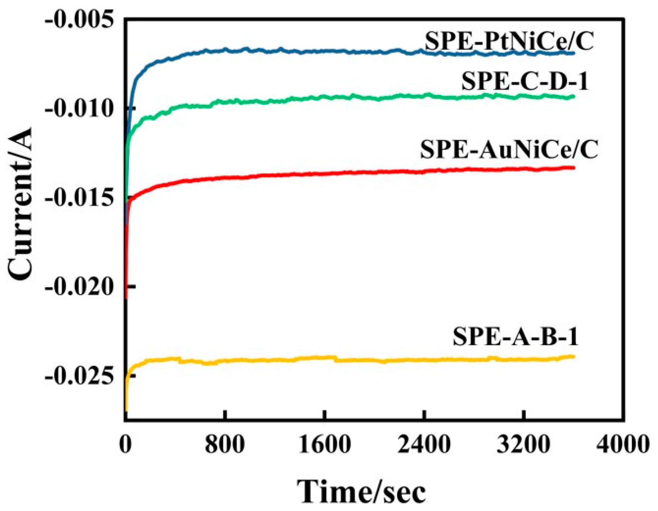
3.6. Electrochemical Activity Analysis
3.7. Analysis of Cyclohexene Hydrogenation Efficiency via Electrocatalysis
4. Conclusions
Supplementary Materials
Author Contributions
Funding
Data Availability Statement
Acknowledgments
Conflicts of Interest
References
- Koh, K.; Sanyal, U.; Lee, M.S.; Cheng, G.; Song, M.; Glezakou, V.A.; Liu, Y.; Li, D.; Rousseau, R.; Gutiérrez, O.Y.; et al. Electrochemically Tunable Proton-Coupled Electron Transfer in Pd-Catalyzed Benzaldehyde Hydrogenation. Angew. Chem. Int. Ed. 2019, 59, 1501–1505. [Google Scholar] [CrossRef] [PubMed]
- Zhang, J.; Xu, J.; Huang, X.; Zhang, Q.; Yang, G.; Liu, Z.; Peng, F. Electrocatalytic hydrogenation of 5-hydroxymethyfurfural reactions promoted by CuZn catalysts. Mater. Today Sustain. 2024, 25, 100653. [Google Scholar] [CrossRef]
- Lebedeva, O.; Kultin, D.; Kalenchuk, A.; Kustov, L. Advances and prospects in electrocatalytic hydrogenation of aromatic hydrocarbons for synthesis of “loaded” liquid organic hydrogen carriers. Curr. Opin. Electrochem. 2023, 38, 101207. [Google Scholar] [CrossRef]
- Sun, K.; Li, K.-J.; Zhang, Z.; Liang, Y.; Liu, Z.; Lee, W.-J. An Integration Scheme of Renewable Energies, Hydrogen Plant, and Logistics Center in the Suburban Power Grid. IEEE Trans. Ind. Appl. 2022, 58, 2771–2779. [Google Scholar] [CrossRef]
- Chen, H.; Dong, S. A method to construct polyelectrolyte multilayers film containing gold nanoparticles. Talanta 2007, 71, 1752–1756. [Google Scholar] [CrossRef] [PubMed]
- Chi, J.; Yu, H. Water electrolysis based on renewable energy for hydrogen production. Chin. J. Catal. 2018, 39, 390–394. [Google Scholar] [CrossRef]
- Chen, Q.; Tsiakaras, P.; Shen, P. Electrochemical Reduction of Carbon Dioxide: Recent Advances on Au-Based Nanocatalysts. Catalysts 2022, 12, 1348. [Google Scholar] [CrossRef]
- Li, C.; Chai, O.J.H.; Yao, Q.; Liu, Z.; Wang, L.; Wang, H.; Xie, J. Electrocatalysis of gold-based nanoparticles and nanoclusters. Mater. Horiz. 2021, 8, 1657–1682. [Google Scholar] [CrossRef]
- Lim, C.; Fairhurst, A.R.; Ransom, B.J.; Haering, D.; Stamenkovic, V.R. Role of Transition Metals in Pt Alloy Catalysts for the Oxygen Reduction Reaction. ACS Catal. 2023, 13, 14874–14893. [Google Scholar] [CrossRef]
- Sha, J.; Paul, S.; Dumeignil, F.; Wojcieszak, R. Au-based bimetallic catalysts: How the synergy between two metals affects their catalytic activity. RSC Adv. 2019, 9, 29888–29901. [Google Scholar] [CrossRef]
- Zhang, C.; Xue, C. Ligand-assisted morphology regulation of AuNi bimetallic nanocrystals for efficient hydrogen evolution. RSC Adv. 2023, 13, 1229–1235. [Google Scholar] [PubMed]
- Ma, J.; Wang, Z.; Majima, T.; Zhao, G. Role of Ni in PtNi Alloy for Modulating the Proton–Electron Transfer of Electrocatalytic Hydrogenation Revealed by the In Situ Raman–Rotating Disk Electrode Method. ACS Catal. 2022, 12, 14062–14071. [Google Scholar] [CrossRef]
- Lonergan, W.W.; Vlachos, D.G.; Chen, J.G. Correlating extent of Pt–Ni bond formation with low-temperature hydrogenation of benzene and 1,3-butadiene over supported Pt/Ni bimetallic catalysts. J. Catal. 2010, 271, 239–250. [Google Scholar]
- Sudarsanam, P.; Mallesham, B.; Reddy, P.S.; Großmann, D.; Grünert, W.; Reddy, B.M. Nano-Au/CeO2 catalysts for CO oxidation: Influence of dopants (Fe, La and Zr) on the physicochemical properties and catalytic activity. Appl. Catal. B Environ. 2014, 144, 900–908. [Google Scholar] [CrossRef]
- Wu, Q.; Eriksen, W.L.; Duchstein, L.D.L.; Christensen, J.M.; Damsgaard, C.D.; Wagner, J.B.; Temel, B.; Grunwaldt, J.-D.; Jensen, A.D. Influence of preparation method on supported Cu–Ni alloys and their catalytic properties in high pressure CO hydrogenation. Catal. Sci. Technol. 2014, 4, 378–386. [Google Scholar]
- Kurabayashi, T.; Yamaki, T.; Fukuda, T.; Kamata, N. Improved Photobleaching for (1,10-phenanthroline)tris [4,4,4-trifluoro-1-(2-thienyl)-1,3-butanedionato]europium(III) Particle Embedded in Sol-Gel Derived Glass Film. Mol. Cryst. Liq. Cryst. 2015, 621, 136–141. [Google Scholar]
- Minelli, S.; Rondinini, S.; He, X.; Vertova, A.; Lenardi, C.; Piazzoni, C.; Locarno, S.; Minguzzi, A. Highly active Pd–ZrO2 electrodes for hydrogen evolution reaction. Sustain. Energy Fuels 2023, 7, 1333–1342. [Google Scholar] [CrossRef]
- Fang, L.; Yang, B.; Cai, J.; Feng, Y.; Li, X.; Li, Y. Electrochemical modification and structural characterization of porous PtNi/C catalyst. J. Alloys Compd. 2021, 879, 160454. [Google Scholar]
- El-Deeb, H.; Nassr, A.B.A.A.; Bron, M. Cu@ Pt/CNT catalysts for oxygen reduction prepared by a facile two-step synthesis: Chemical vs. electrochemical leaching. J. Electroanal. Chem. 2023, 946, 117724. [Google Scholar]
- Chistyakov, A.V.; Zharova, P.A.; Tsodikov, M.V.; Nikolaev, S.A.; Krotova, I.N.; Ezzhelenko, D.I. Conversion of ethanol into linear primary alcohols on gold, nickel, and gold–nickel catalysts. Kinet. Catal. 2016, 57, 803–811. [Google Scholar]
- Tao, F.; Zhang, S.; Nguyen, L.; Zhang, X. Action of bimetallic nanocatalysts under reaction conditions and during catalysis: Evolution of chemistry from high vacuum conditions to reaction conditions. Chem. Soc. Rev. 2012, 41, 7980–7993. [Google Scholar] [PubMed]
- Wu, N.; Li, B. A Novel Synthesis of Highly Dispersed Bimetallic Catalysts Pt@M-MCM-41 (M = Ni, Co) for Hydrocracking of Residual Oil. Chem. Lett. 2016, 45, 499–501. [Google Scholar] [CrossRef]
- Liu, H.-l.; Nosheen, F.; Wang, X. Noble metal alloy complex nanostructures: Controllable synthesis and their electrochemical property. Chem. Soc. Rev. 2015, 44, 3056–3078. [Google Scholar]
- Ma, K.; Corsi, J.S.; Fu, J.; Detsi, E. Origin of the Volume Contraction during Nanoporous Gold Formation by Dealloying for High-Performance Electrochemical Applications. ACS Appl. Nano Mater. 2018, 1, 541–546. [Google Scholar]
- Gan, L.; Cui, C.; Rudi, S.; Strasser, P. Core–Shell and Nanoporous Particle Architectures and Their Effect on the Activity and Stability of Pt ORR Electrocatalysts. Top. Catal. 2013, 57, 236–244. [Google Scholar]
- Wang, Q.; Wang, G.; Tao, H.; Li, Z.; Han, L. Highly CO tolerant PtRu/PtNi/C catalyst for polymer electrolyte membrane fuel cell. RSC Adv. 2017, 7, 8453–8459. [Google Scholar]
- Yadav, N. Cerium oxide nanostructures: Properties, biomedical applications and surface coatings. 3 Biotech 2022, 12, 121. [Google Scholar]
- Raza Naqvi, S.T.; Shirinfar, B.; Majeed, S.; Najam-ul-Haq, M.; Hussain, D.; Iqbal, T.; Ahmed, N. Synthesis, design and sensing applications of nanostructured ceria-based materials. Analyst 2018, 143, 5610–5628. [Google Scholar]
- Yu, X.; Sun, Z.; Yan, Z.; Xiang, B.; Liu, X.; Du, P. Direct growth of porous crystalline NiCo2O4 nanowire arrays on a conductive electrode for high-performance electrocatalytic water oxidation. J. Mater. Chem. A 2014, 2, 20823–20831. [Google Scholar]
- Liu, L.; Tai, X.; Zhou, X.; Hou, J.; Zhang, Z. Compounds, Bimetallic Au–Ni alloy nanoparticles in a metal–organic framework (MIL-101) as efficient heterogeneous catalysts for selective oxidation of benzyl alcohol into benzaldehyde. J. Alloys Compd. 2019, 790, 326–336. [Google Scholar]
- Ding, L.-X.; Wang, A.-L.; Li, G.-R.; Liu, Z.-Q.; Zhao, W.-X.; Su, C.-Y.; Tong, Y.-X. Porous Pt-Ni-P Composite Nanotube Arrays: Highly Electroactive and Durable Catalysts for Methanol Electrooxidation. J. Am. Chem. Soc. 2012, 134, 5730–5733. [Google Scholar] [CrossRef] [PubMed]
- Ze, H.; Chen, X.; Wang, X.-T.; Wang, Y.-H.; Chen, Q.-Q.; Lin, J.-S.; Zhang, Y.-J.; Zhang, X.-G.; Tian, Z.-Q.; Li, J.-F. Molecular Insight of the Critical Role of Ni in Pt-Based Nanocatalysts for Improving the Oxygen Reduction Reaction Probed Using an In Situ SERS Borrowing Strategy. J. Am. Chem. Soc. 2021, 143, 1318–1322. [Google Scholar] [CrossRef]
- Hao, J.; Zhu, H.; Li, Y.; Liu, P.; Lu, S.; Duan, F.; Dong, W.; Lu, Y.; Liu, T.; Du, M. Tuning the electronic structure of AuNi homogeneous solid-solution alloy with positively charged Ni center for highly selective electrochemical CO2 reduction. Chem. Eng. J. 2021, 404, 126523. [Google Scholar] [CrossRef]
- Ruppert, A.M.; Jędrzejczyk, M.; Potrzebowska, N.; Kaźmierczak, K.; Brzezińska, M.; Sneka-Płatek, O.; Sautet, P.; Keller, N.; Michel, C.; Grams, J. Supported gold–nickel nano-alloy as a highly efficient catalyst in levulinic acid hydrogenation with formic acid as an internal hydrogen source. Catal. Sci. Technol. 2018, 8, 4318–4331. [Google Scholar] [CrossRef]
- Tian, Y.; Guo, L.; Qiao, C.; Sun, Z.; Yamauchi, Y.; Liu, S. Dynamics-driven tailoring of sub-nanometric Pt-Ni bimetals confined in hierarchical zeolite for catalytic hydrodeoxygenation. Appl. Catal. B Environ. 2023, 336, 122945. [Google Scholar] [CrossRef]
- Mel’gunov, M.S. Application of the simple Bayesian classifier for the N2 (77 K) adsorption/desorption hysteresis loop recognition. Adsorption 2023, 29, 199–208. [Google Scholar] [CrossRef]
- Zhao, X.; Jia, J.; Shi, H.; Li, S.; Xu, C. Strong electronic interaction enhanced electrocatalysis of copper phthalocyanine decorated Co-MOF-74 toward highly efficient oxygen evolution reaction. RSC Adv. 2024, 14, 40173–40178. [Google Scholar]
- Liang, J.; Fu, C.; Hwang, S.; Dun, C.; Luo, L.; Shadike, Z.; Shen, S.; Zhang, J.; Xu, H.; Wu, G. Constructing Highly Porous Low Iridium Anode Catalysts via Dealloying for Proton Exchange Membrane Water Electrolyzers. Adv. Mater. 2024, 37, 2409386. [Google Scholar]
- Wei, C.; Sun, S.; Mandler, D.; Wang, X.; Qiao, S.Z.; Xu, Z.J. Approaches for measuring the surface areas of metal oxide electrocatalysts for determining their intrinsic electrocatalytic activity. Chem. Soc. Rev. 2019, 48, 2518–2534. [Google Scholar] [CrossRef]
- Imada, T.; Iida, Y.; Ueda, Y.; Chiku, M.; Higuchi, E.; Inoue, H. Electrochemical Toluene Hydrogenation Using Binary Platinum-Based Alloy Nanoparticle-Loaded Carbon Catalysts. Catalysts 2021, 11, 318. [Google Scholar] [CrossRef]


| Parameters | Anode Voltage (V) | Cathode Current (A) | Screen Voltage (kV) | Acceleration Voltage (V) | Beam Current (mA) | Gas Flow Rate (sccm) | Time (s) | Gas Type | |
|---|---|---|---|---|---|---|---|---|---|
| Process | |||||||||
| Auxiliary Cleaning | 58 | 14 | 0.5 | 200 | 50 | 8.8 | 300 | N2 | |
| Sputtering Preparation | 50 | 12 | 2.0 | 140 | 70 | 5.2 | 900 | Ar | |
| Samples | SPE-AuNiCe | SPE-PtNiCe | SPE-A-B-1 | SPE-C-D-1 |
|---|---|---|---|---|
| SSA | 144.9 | 174.9 | 457.7 | 358.6 |
| Samples | Au (mg·cm−2) | Pt (mg·cm−2) | Ni (mg·cm−2) | Ce (mg·cm−2) | Au (%) | Pt (%) |
|---|---|---|---|---|---|---|
| SPE-AuNiCe/C | 0.121339 | - | 0.047167 | 0.003440 | 70.60 | - |
| SPE-A-B-1 | 0.045874 | - | 0.000408 | 0.000200 | 98.69 | - |
| SPE-PtNiCe/C | - | 0.128110 | 0.011250 | 0.0029901 | - | 90.00 |
| SPE-C-D-1 | - | 0.073580 | 0.001790 | 0.000270 | - | 94.24 |
| Samples | (%) | (%) | η (%) | Q (×10−3A) | Q1 (×10−3A) |
|---|---|---|---|---|---|
| SPE-AuNiCe/C | 1.53 | 0.83 | 64.72 | 13.55 | 8.77 |
| SPE-A-B-1 | 5.77 | 0.79 | 88.00 | 24.09 | 21.20 |
| SPE-PtNiCe/C | 0.85 | 1.39 | 38.05 | 6.86 | 2.61 |
| SPE-C-D-1 | 2.34 | 1.46 | 61.45 | 9.40 | 5.78 |
Disclaimer/Publisher’s Note: The statements, opinions and data contained in all publications are solely those of the individual author(s) and contributor(s) and not of MDPI and/or the editor(s). MDPI and/or the editor(s) disclaim responsibility for any injury to people or property resulting from any ideas, methods, instructions or products referred to in the content. |
© 2025 by the authors. Licensee MDPI, Basel, Switzerland. This article is an open access article distributed under the terms and conditions of the Creative Commons Attribution (CC BY) license (https://creativecommons.org/licenses/by/4.0/).
Share and Cite
Wang, S.; Feng, Y.; Duan, L.; Shang, Y.; Fan, H.; Liu, J.; Han, J.; Wang, X.; Yang, B. Controlled Synthesis of Mesoporous Solid Polymer Electrolyte Au(Pt)NiCe/C Membrane Electrode for Electrocatalytic Hydrogenation. Micromachines 2025, 16, 436. https://doi.org/10.3390/mi16040436
Wang S, Feng Y, Duan L, Shang Y, Fan H, Liu J, Han J, Wang X, Yang B. Controlled Synthesis of Mesoporous Solid Polymer Electrolyte Au(Pt)NiCe/C Membrane Electrode for Electrocatalytic Hydrogenation. Micromachines. 2025; 16(4):436. https://doi.org/10.3390/mi16040436
Chicago/Turabian StyleWang, Shaqin, Yunhao Feng, Liangming Duan, Yueming Shang, Huaihang Fan, Ji Liu, Jiahao Han, Xiaoqi Wang, and Bin Yang. 2025. "Controlled Synthesis of Mesoporous Solid Polymer Electrolyte Au(Pt)NiCe/C Membrane Electrode for Electrocatalytic Hydrogenation" Micromachines 16, no. 4: 436. https://doi.org/10.3390/mi16040436
APA StyleWang, S., Feng, Y., Duan, L., Shang, Y., Fan, H., Liu, J., Han, J., Wang, X., & Yang, B. (2025). Controlled Synthesis of Mesoporous Solid Polymer Electrolyte Au(Pt)NiCe/C Membrane Electrode for Electrocatalytic Hydrogenation. Micromachines, 16(4), 436. https://doi.org/10.3390/mi16040436