
Study of Charged Nanodroplet Deposition into Microcavity Through Many-Body Dissipative Particle Dynamics


Abstract
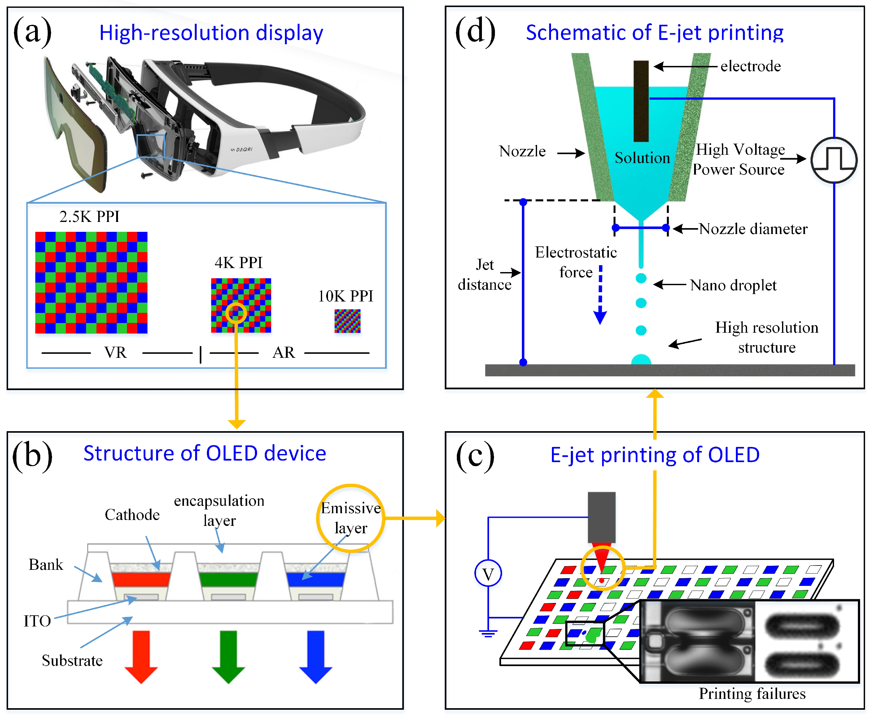
1. Introduction
2. Methodology and Model
3. Results and Discussion
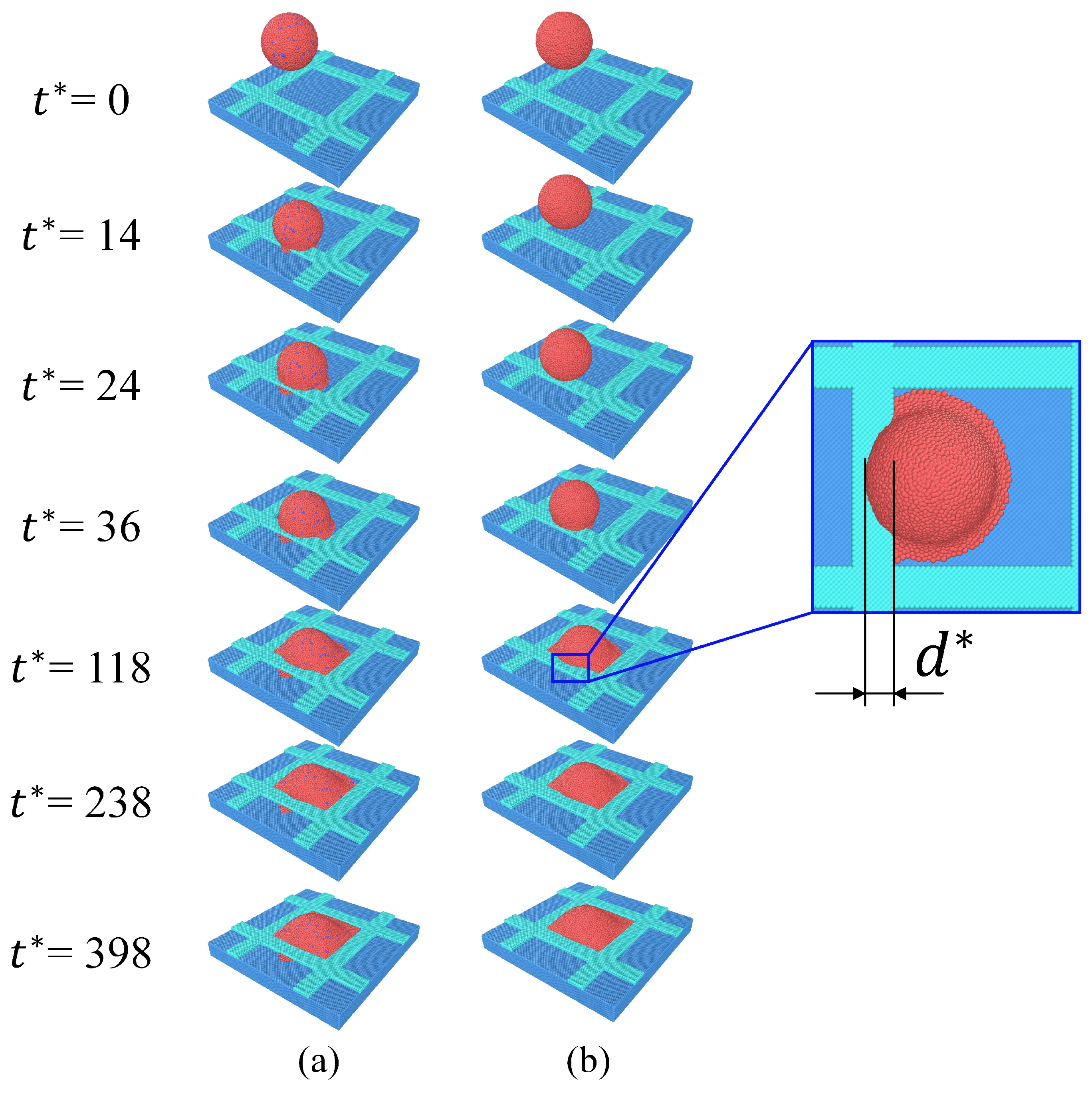
3.1. Description of the Morphologies of the Charged Nanodroplet Deposition
3.2. Influence of Different Parameters on Out-of-Pixel Spreading Length
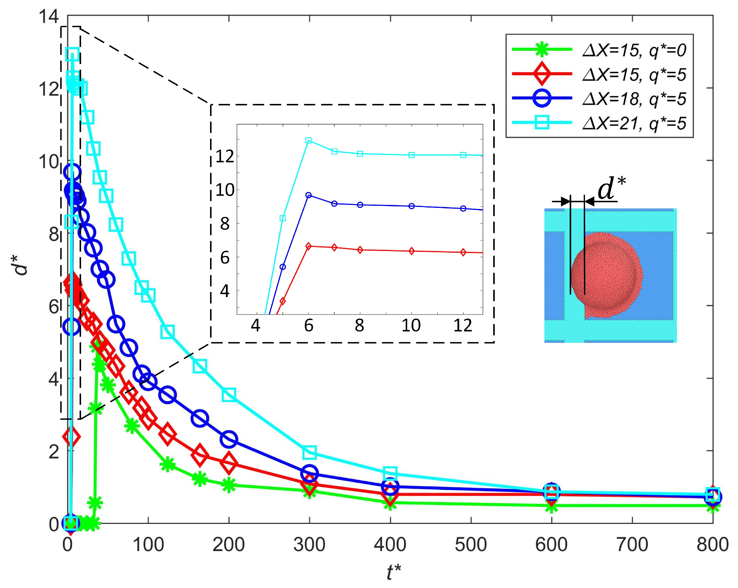
3.2.1. Influence of Droplet Positioning Error
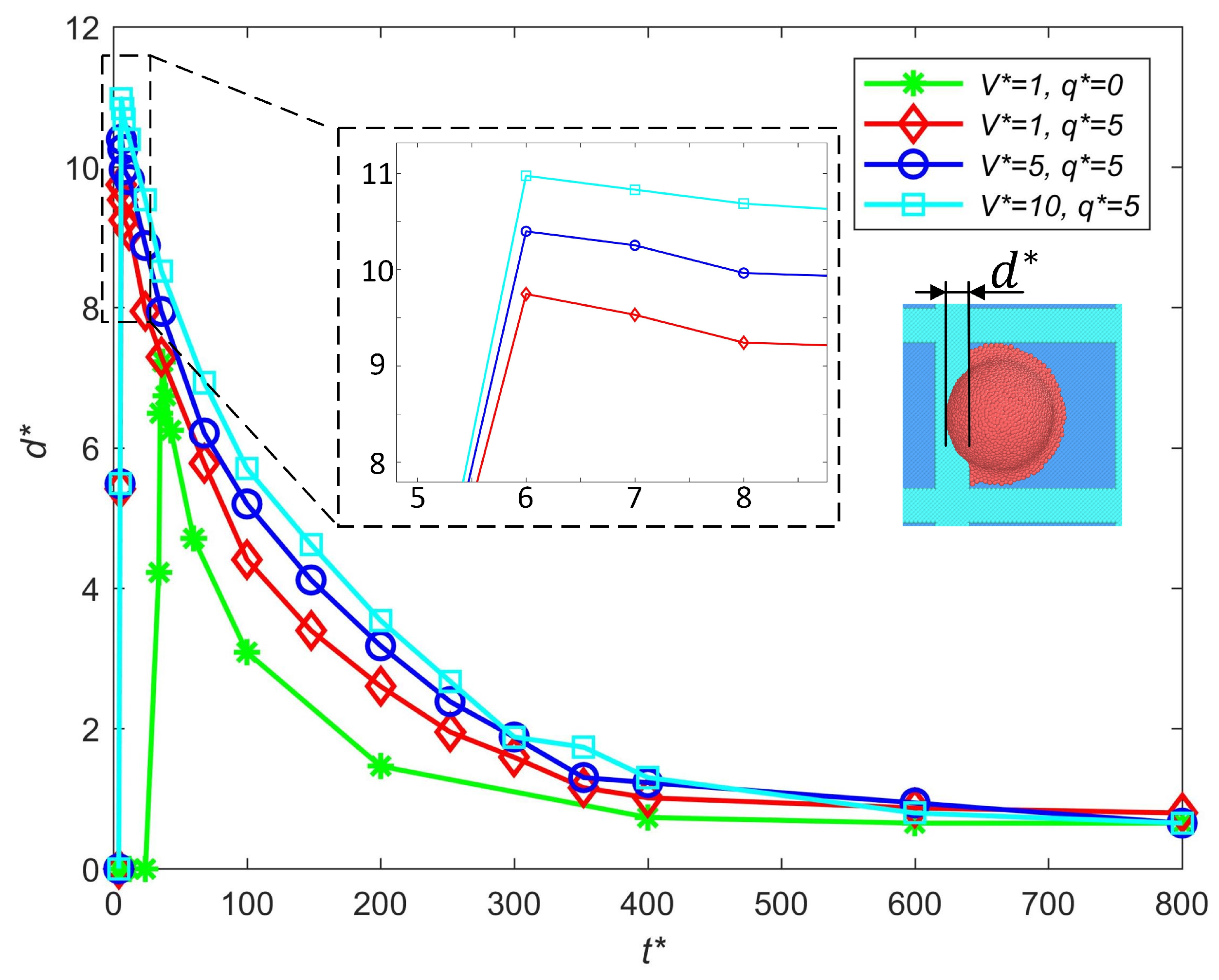
3.2.2. Influence of Impact Speed
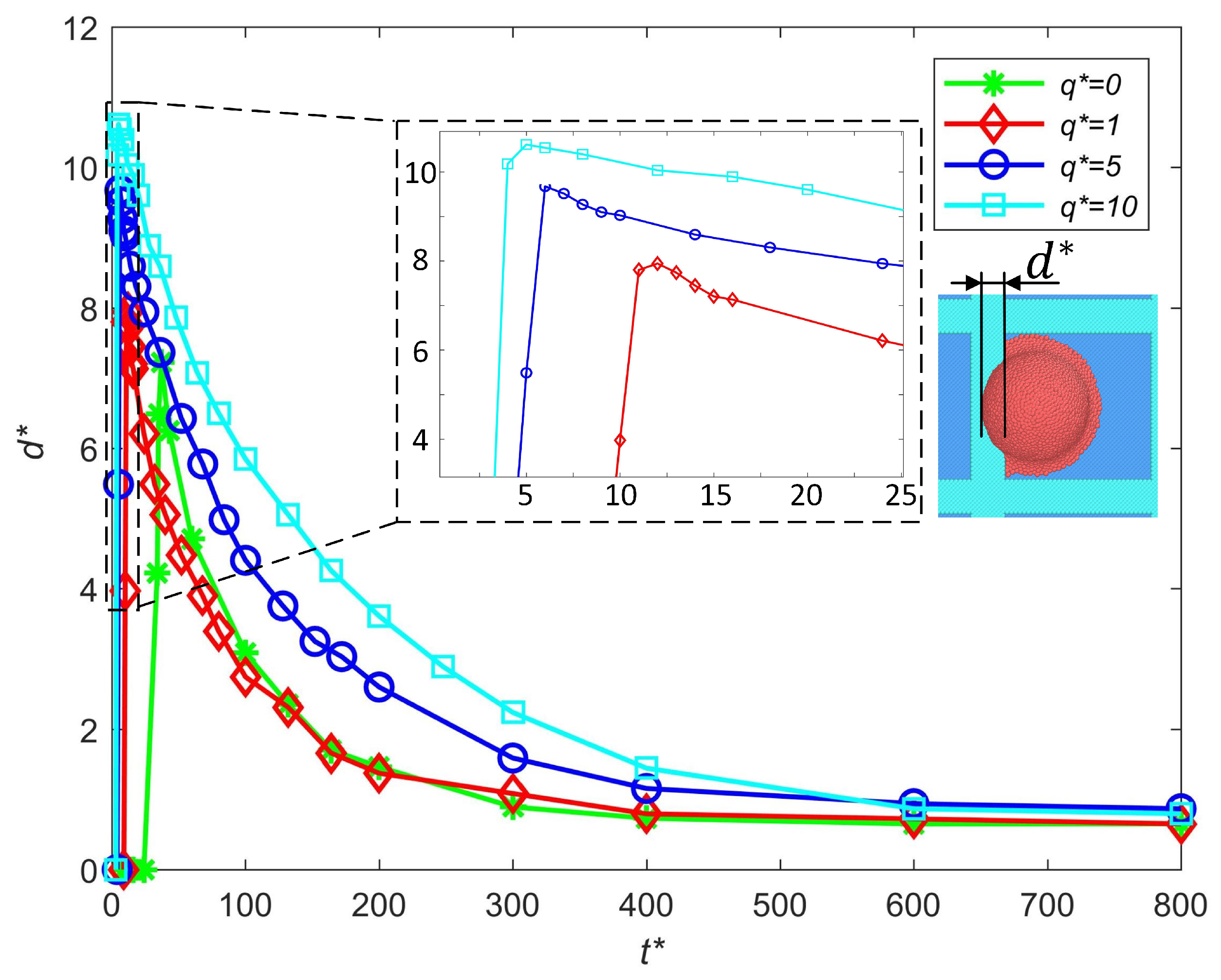
3.2.3. Influence of Charge Levels
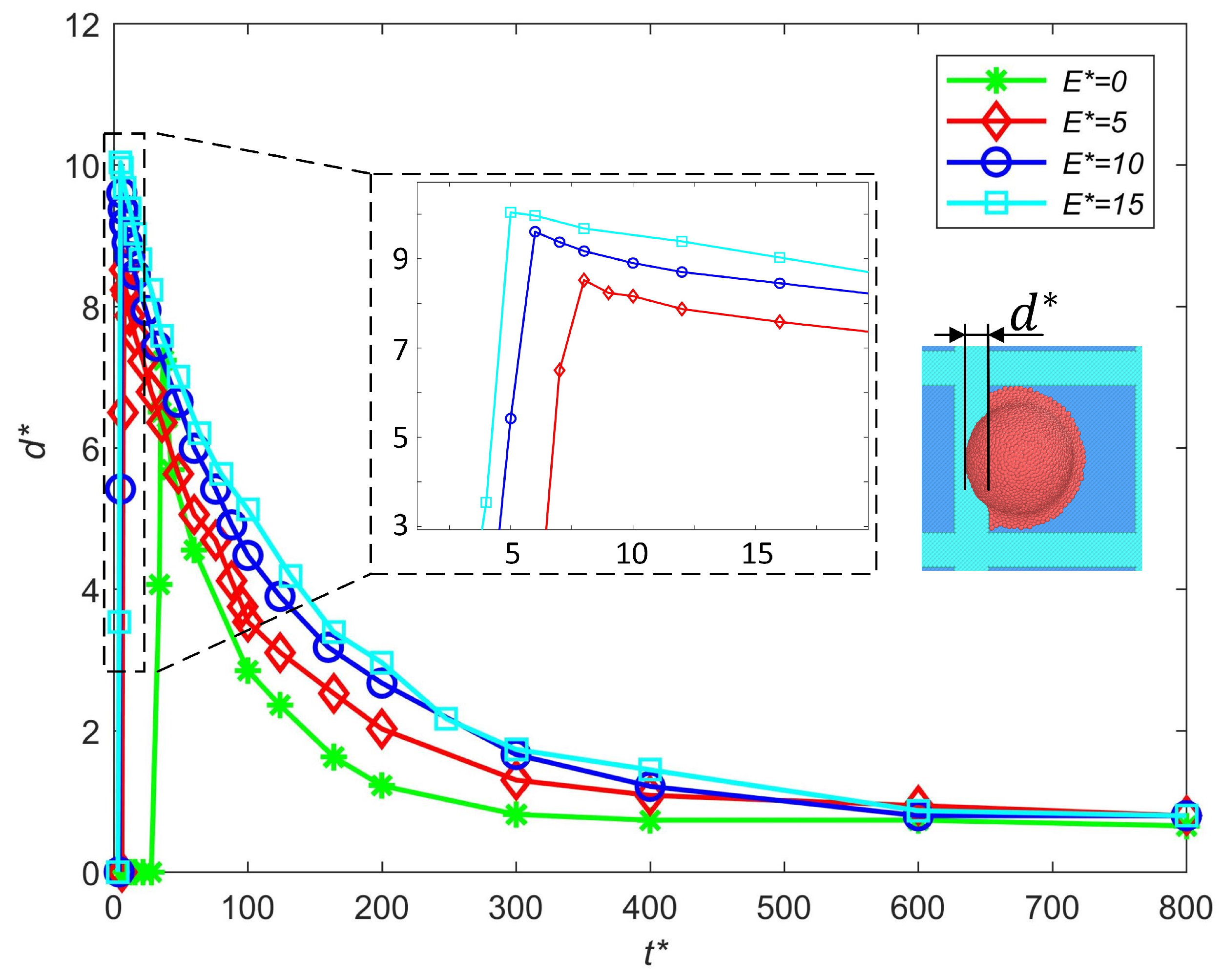
3.2.4. Influence of Electric Intensities
3.3. The Charge Moves and the Failure-Free Printing Parameter Space
4. Conclusions
- Strategies for failure-free printing are proposed, where increasing the impact speed will enlarge the out-of-pixel spreading length due to an increase in the initial kinetic energy. Increasing the charge level and electric field intensity will both increase the out-of-pixel spreading length by decreasing the surface tension and enhancing the electrowetting effect. To avoid excessive out-of-pixel spreading, an appropriate waveform is needed to make the impact of the droplet occur at a relatively low speed while maintaining stable fracture. Based on the premise of stable ejection, a larger dielectric constant of the ink and a smaller intensity of the electric field are better for failure-free printing.
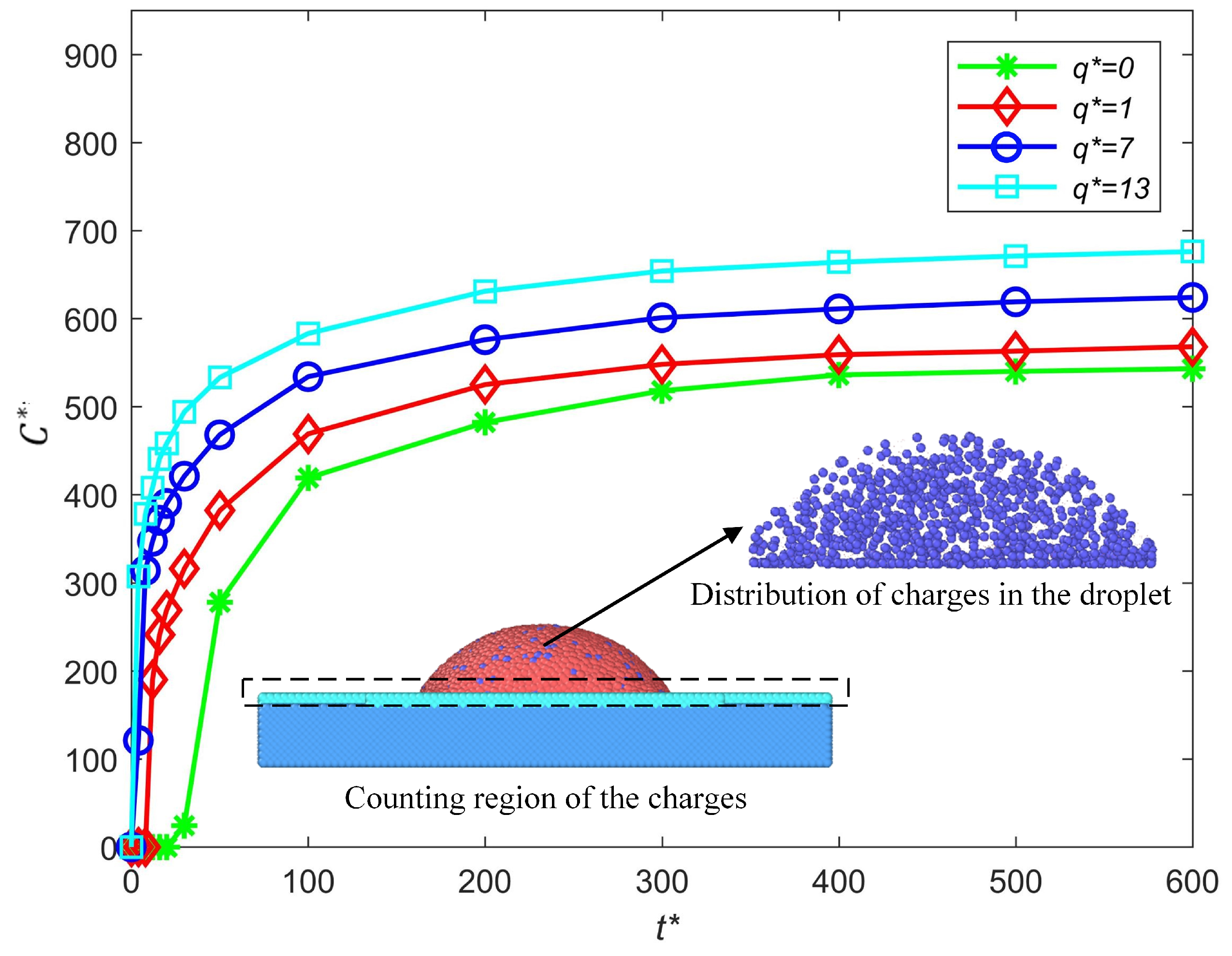
- The relationship between the internal charge moves and the deformation of the charged droplet in the deposition process is first discussed. The electric force changes the distribution of the charges in the droplet and more charges are driven toward the substrate with the increase in the electric force of the charged particles.
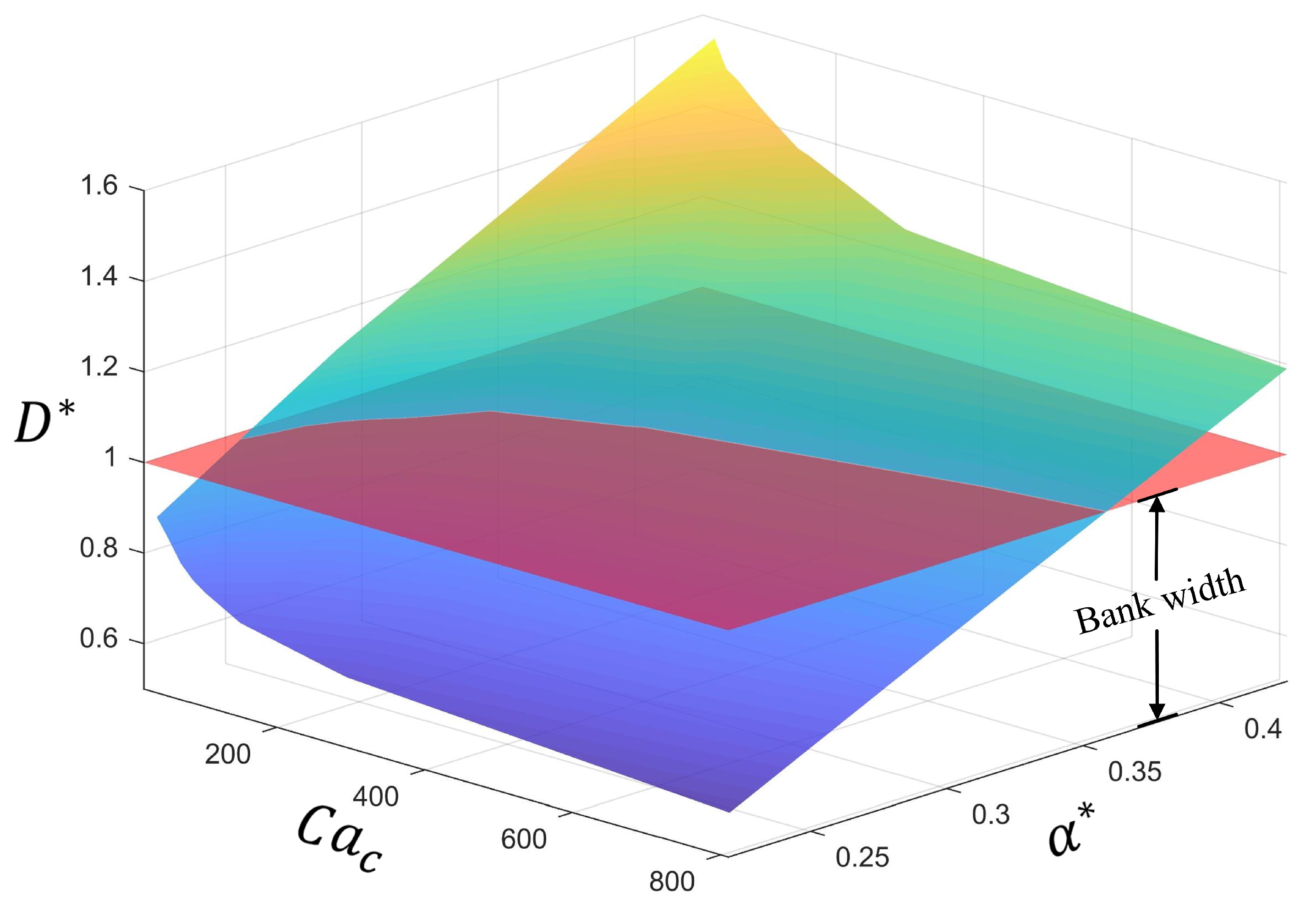
- The spreading theory of charged droplet deposition into a microcavity with a positioning error is established by analyzing the Coulombic capillary number. Moreover, the printing parameter space that results in successful printing is acquired.
Author Contributions
Funding
Data Availability Statement
Conflicts of Interest
References
- Joo, W.J.; Kyoung, J.; Esfandyarpour, M.; Lee, S.-H.; Koo, H.; Song, S.; Kwon, Y.-N.; Song, S.H.; Bae, J.C.; Jo, A.; et al. Metasurface-driven OLED displays beyond 10,000 pixels per inch. Science 2020, 370, 459–463. [Google Scholar] [CrossRef] [PubMed]
- Kim, S.K. Effect of Computational Lithography Parameters on the Organic Light-Emitting Diodes. J. Nanosci. Nanotechnol. 2016, 16, 8496–8499. [Google Scholar] [CrossRef]
- Jun, S.; Kim, M.; Kim, S.H.; Lee, M.Y.; Lee, E.K. A study on the evaporation process with multiple point-sources. Electron. Mater. Lett. 2013, 9, 7–11. [Google Scholar] [CrossRef]
- Yin, Z.P.; Wang, D.; Guo, Y.; Zhao, Z.; Li, L.; Chen, W.; Duan, Y. Electrohydrodynamic printing for high resolution patterning of flexible electronics toward industrial applications. InfoMat 2023, 6, e12505. [Google Scholar] [CrossRef]
- Yakunin, S.; Chaaban, J.; Benin, B.M.; Cherniukh, I.; Bernasconi, C.; Landuyt, A.; Shynkarenko, Y.; Bolat, S.; Hofer, C.; Romanyuk, Y.E.; et al. Radiative lifetime-encoded unicolour security tags using perovskite nanocrystals. Nat. Commun. 2021, 12, 981. [Google Scholar] [CrossRef]
- Yang, X.; Yan, Z.J.; Zhong, C.M.; Jia, H.; Chen, G.; Fan, X.; Wang, S.; Wu, T.; Lin, Y.; Chen, Z. Electrohydrodynamically printed high-resolution arrays based on stabilized CsPbBr3 quantum dot inks. Adv. Opt. Mater. 2023, 11, 2202673. [Google Scholar] [CrossRef]
- Yarin, A.L. Drop impact dynamics: Splashing, spreading, receding, bouncing…. Annu. Rev. Fluid Mech. 2006, 38, 159–192. [Google Scholar] [CrossRef]
- Gomaa, H.; Tembely, M.; Esmail, N.; Dolatabadi, A. Bouncing of cloud-sized microdroplets on superhydrophobic surfaces. Phys. Fluids 2020, 32, 122118. [Google Scholar] [CrossRef]
- Pan, X.; Wang, Y.; Shen, M. A conservative level set approach to non-spherical drop impact in three dimensions. Micromachines 2022, 13, 1850. [Google Scholar] [CrossRef] [PubMed]
- Xu, B.; Zhang, C.; Chen, Z.; Yang, Y.; Cao, Q. Investigation of nano-droplet wetting states on array micro-structured surfaces with different gravity. Comput. Fluids 2021, 222, 104936. [Google Scholar] [CrossRef]
- Hasan, M.N.; Chandy, A.; Choi, J.W. Numerical analysis of post-impact droplet deformation for direct-print. Eng. Appl. Comput. Fluid Mech. 2015, 9, 543–555. [Google Scholar]
- Ghazian, O.; Adamiak, K.; Castle, G.S.P. Spreading and retraction control of charged dielectric droplets. Colloids Surf. A 2014, 448, 23–33. [Google Scholar] [CrossRef]
- Liu, R.; Wang, Y.B.; Yang, S.W.; Liu, H.-W.; Yang, Y.-R.; Wang, X.-D.; Lee, D.-J. Impacting-bouncing nanodroplets on superhydrophobic surfaces under electric fields. Colloids Surf. A 2021, 629, 127513. [Google Scholar] [CrossRef]
- Shen, M.; Li, B.Q.; Yang, Q. A 3-D phase field study of dielectric droplet impact under a horizontal electric field. Int. J. Multiphase Flow 2023, 162, 104385. [Google Scholar] [CrossRef]
- Xu, H.; Wang, J.; Yu, K.; Li, B.; Zhang, W.; Zuo, L.; Kim, H.-B. Droplet impact on hot substrates under a uniform electric field. Phys. Fluids 2022, 34, 092111. [Google Scholar] [CrossRef]
- Liou, T.M.; Chan, C.Y.; Shih, K.C. Study of the characteristics of polymer droplet deposition in fabricated rectangular microcavities. J. Micromech. Microeng. 2009, 19, 065028. [Google Scholar] [CrossRef]
- Zhang, L.; Cheng, X.; Ku, T.; Song, Y.; Zhang, D. Lattice Boltzmann study of successive droplets impingement on the non-ideal recessed microchannel for high-resolution features. Int. J. Heat Mass Transfer 2018, 120, 1085–1100. [Google Scholar] [CrossRef]
- Zhang, L.; Ku, T.; Cheng, X.; Song, Y.; Zhang, D. Inkjet droplet deposition dynamics into square microcavities for OLEDs manufacturing. Microfluid. Nanofluid. 2018, 22, 47. [Google Scholar] [CrossRef]
- Jackson, F.F.; Kubiak, K.J.; Wilson, M.C.T.; Molinari, M.; Stetsyuk, V. Droplet misalignment limit for inkjet printing into cavities on textured surfaces. Langmuir 2019, 35, 9564–9571. [Google Scholar] [CrossRef]
- Zhang, L.; Wang, X. Evaporation-driven nanoparticles motion and deposition on a textured surface in the inkjet process. Eng. Appl. Comput. Fluid Mech. 2021, 15, 644–655. [Google Scholar] [CrossRef]
- Groot, R.D.; Warren, P.B. Dissipative particle dynamics: Bridging the gap between atomistic and mesoscopic simulation. J. Chem. Phys. 1997, 107, 4423–4435. [Google Scholar] [CrossRef]
- Arienti, M.; Pan, W.; Li, X.; Karniadakis, G. Many-body dissipative particle dynamics simulation of liquid/vapor and liquid/solid interactions. J. Chem. Phys. 2011, 134, 204114. [Google Scholar] [CrossRef]


(nm) | (ns) | (nm/ns) | ||||||||
|---|---|---|---|---|---|---|---|---|---|---|
| −209.5 | 1870 | 3 | 1.5 | 8 | 0.8 | 99 | 1 | 4.58 | 0.802 | 5.715 |
| Parameters | ||||||||
|---|---|---|---|---|---|---|---|---|
| Between droplet and bank | −45 | 1200 | 3.6 | 1.8 | 8 | 0.8 | 99 | 1 |
| Between droplet and substrate | −85 | 1200 | 3.6 | 1.8 | 8 | 0.8 | 99 | 1 |
| 14.25 | 44 | 2 | 9 | 18 | 0 | 1 | 10 | 5 | 976 | 0 |
| Parameters | |||||||||
|---|---|---|---|---|---|---|---|---|---|
| Value | 6 | 178 | 61.36 | 14.25 | 0.05 | 3~19 | 99 | 0.8 | 3 |
Disclaimer/Publisher’s Note: The statements, opinions and data contained in all publications are solely those of the individual author(s) and contributor(s) and not of MDPI and/or the editor(s). MDPI and/or the editor(s) disclaim responsibility for any injury to people or property resulting from any ideas, methods, instructions or products referred to in the content. |
© 2025 by the authors. Licensee MDPI, Basel, Switzerland. This article is an open access article distributed under the terms and conditions of the Creative Commons Attribution (CC BY) license (https://creativecommons.org/licenses/by/4.0/).
Share and Cite
Jin, Y.; Chen, J.; Chen, W.; Yin, Z. Study of Charged Nanodroplet Deposition into Microcavity Through Many-Body Dissipative Particle Dynamics. Micromachines 2025, 16, 278. https://doi.org/10.3390/mi16030278
Jin Y, Chen J, Chen W, Yin Z. Study of Charged Nanodroplet Deposition into Microcavity Through Many-Body Dissipative Particle Dynamics. Micromachines. 2025; 16(3):278. https://doi.org/10.3390/mi16030278
Chicago/Turabian StyleJin, Yiwei, Jiankui Chen, Wei Chen, and Zhouping Yin. 2025. "Study of Charged Nanodroplet Deposition into Microcavity Through Many-Body Dissipative Particle Dynamics" Micromachines 16, no. 3: 278. https://doi.org/10.3390/mi16030278
APA StyleJin, Y., Chen, J., Chen, W., & Yin, Z. (2025). Study of Charged Nanodroplet Deposition into Microcavity Through Many-Body Dissipative Particle Dynamics. Micromachines, 16(3), 278. https://doi.org/10.3390/mi16030278