
Surface Characteristics and Fatigue Resistance of Ultrasonic Rolling-Treated 20Cr1Mo1V1A Valve Stem

Abstract
1. Introduction
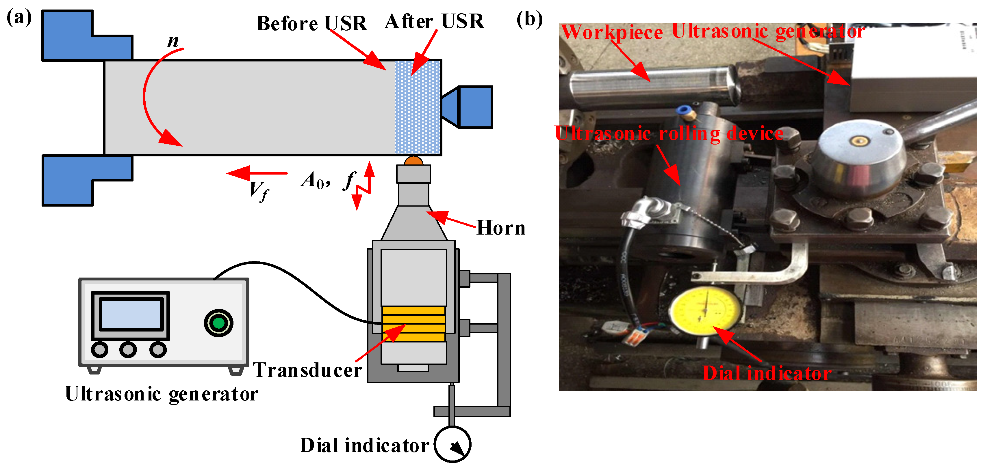
2. Experimental
3. Surface Characteristics
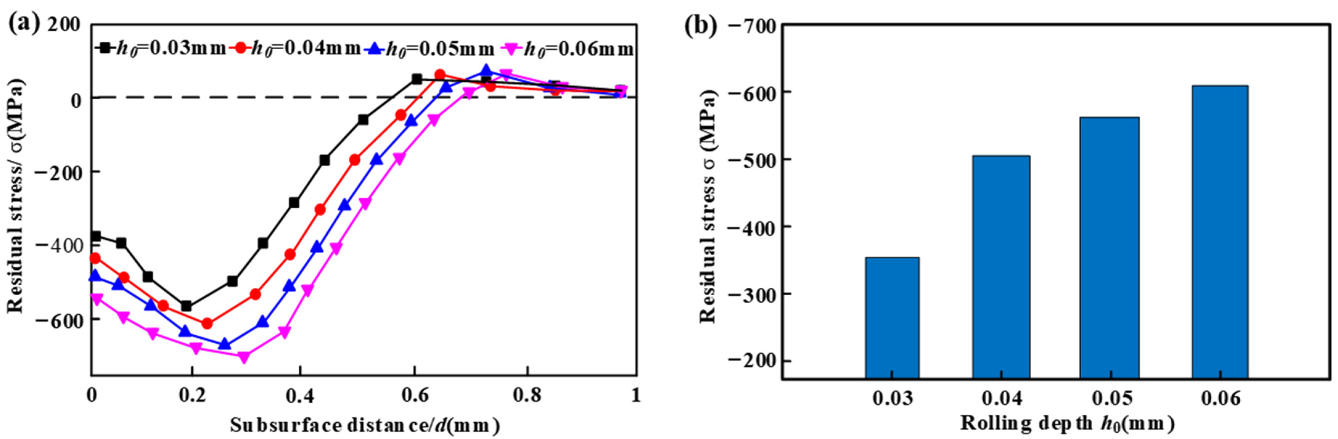
3.1. Residual Stress
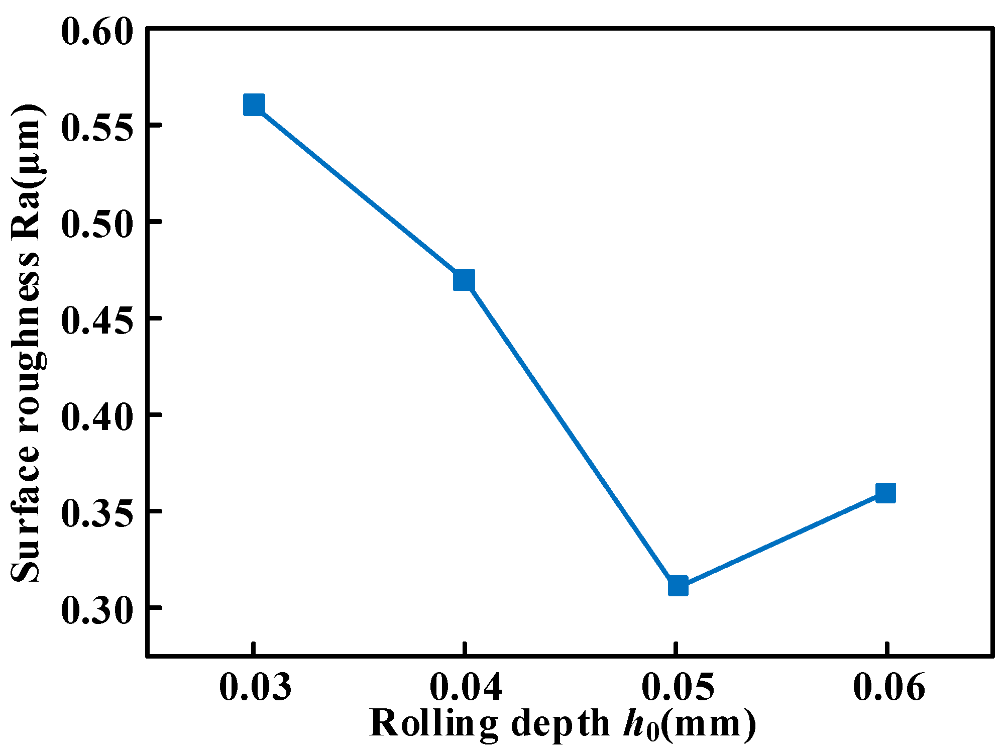
3.2. Surface Roughness and Morphology
3.3. Hardness and Plastic Deformation Layer
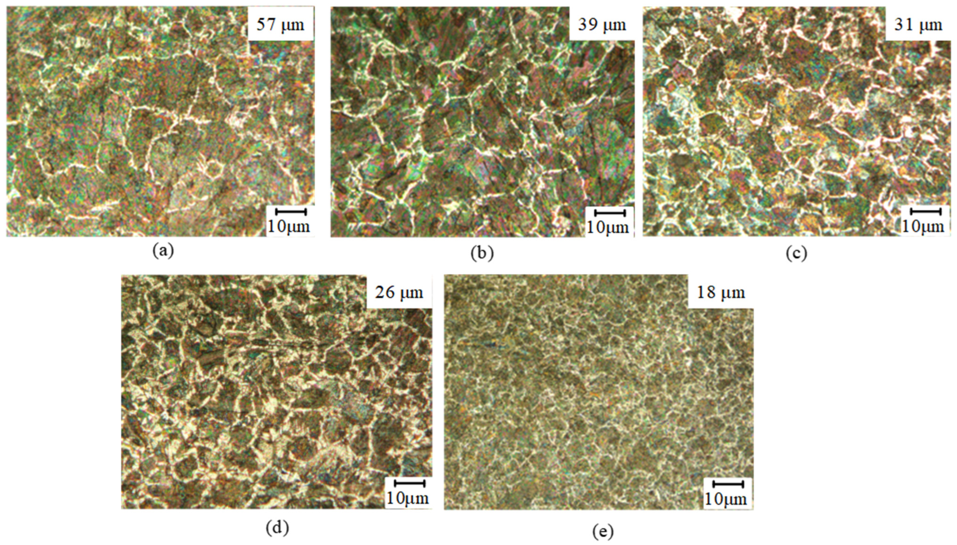
3.4. Gradient Grain Distribution
4. Anti-Fatigue Characteristics
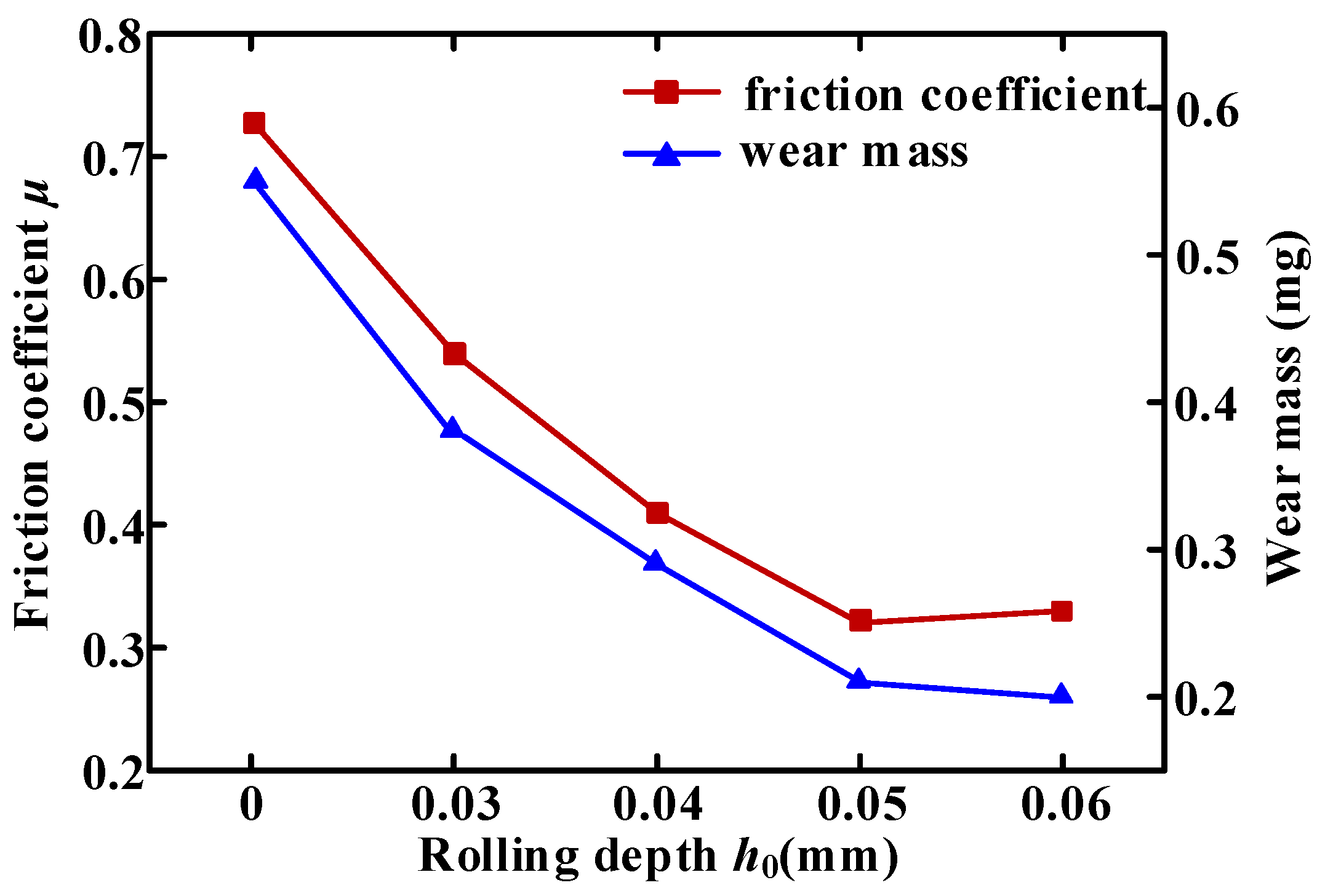
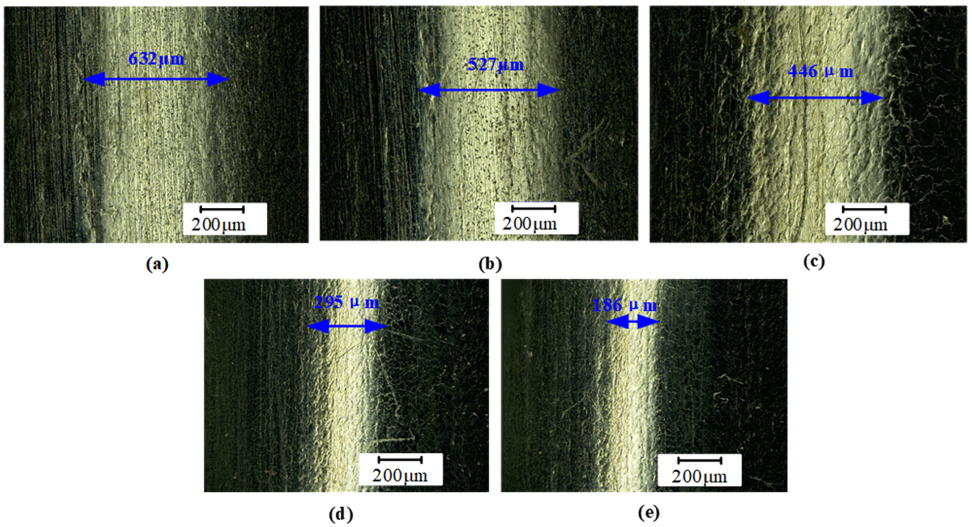
4.1. Friction Coefficient and Wear Amount
4.2. Corrosion Behavior
5. Conclusions
- (1)
- When the rolling depth was precisely set at 0.05 mm, the surface roughness reached an optimal level of 0.32 μm. At this depth, several key surface and subsurface properties were significantly enhanced. The surface hardness was measured at 1087 Hv, while the residual compressive stress reached −489 MPa. Both the deep hardening layer and the plastic deformation layer extended to a depth of 59 μm. The grain size was also reduced to approximately 26 μm, with coarser grains observed at greater depths.
- (2)
- Ultrasonic rolling significantly improved the wear resistance of the 20Cr1Mo1V1A valve stem. Compared to the untreated sample, the friction coefficient and wear mass were reduced by 57% and 69%, respectively. Moreover, the friction width was substantially decreased from 632 μm to 195 μm.
- (3)
- The corrosion resistance of the 20Cr1Mo1V1A valve stem treated with ultrasonic rolling was notably superior to that of the untreated samples when exposed to a 3.5 wt% NaCl aqueous solution. Specifically, the radius and area of corrosion pits were approximately halved compared to those of the untreated samples.
Author Contributions
Funding
Institutional Review Board Statement
Data Availability Statement
Conflicts of Interest
References
- Zhang, W.Z.; Zhao, P.B.; Zhang, Z.L.; Liu, F.M. Fluid-structure interaction and resonance characteristics of large diameter butterfly valve. J. Vibr. Shock 2021, 40, 278–284+291. [Google Scholar]
- Liu, X.Y.; Zhao, P.J.; Zhang, Y.; Yuan, C.Y. Review of key points of marine valves design. Mech. Res. Appl. 2021, 34, 145–147. [Google Scholar]
- Peng, B.; Wang, J.G.; Pei, G.H.; Xin, L.X.; Wang, Z.C. Fracture cause of electric gate valve stem in a 1000MW ultra-supercritical unit. Mater. Mech. Eng. 2021, 45, 104–110. [Google Scholar]
- Xu, A.C.; Yuan, B.X. The study of microstructure, corrosion resistance and mechanical properties of ultrasonic assisted welding-brazing of Ti-Mg. Sci. Direct J. Mater. Res. Technol. 2022, 17, 467–477. [Google Scholar] [CrossRef]
- Shen, Y.Z.; Li, D.F.; Guo, S.L.; Guo, J.T. Effect of heat treatment on microstructure and mechanical properties of Mg-10Li-3Al-3Zn-0.22Si alloy. Met. Mater. Int. 2022, 28, 2462–2471. [Google Scholar] [CrossRef]
- Han, J.; Wang, C.; Song, Y.M.; Liu, Z.Y.; Sun, J.P.; Zhao, J.Y. Simultaneously improving mechanical properties and corrosion resistance of as-cast, AZ91 Mg alloy by ultrasonic surface rolling. Int. J. Miner. Metall. Mater. 2022, 29, 1551–1558. [Google Scholar] [CrossRef]
- Wang, T. Influence of surface nanocrystallization of 20CrMnTi on behavior of localized corrosion by ultrasonic surface rolling processing. Surf. Tech. 2019, 48, 136–143. [Google Scholar]
- Zhu, Y.L.; Li, L.; Wang, K.; Huang, Y.L. An integrated ultrasonic deep rolling and burnishing technology for anti-fatigue manufacturing. J. Mech. Eng. 2009, 45, 184–186. [Google Scholar] [CrossRef]
- Bozdana, A.T.; Gindy, N.N.Z. Comparative experimental study on effects of conventional and ultrasonic deep cold rolling processes on Ti-6Al-4V. Mater. Sci. Technol. 2008, 24, 1378–1384. [Google Scholar] [CrossRef]
- Cheng, M.L.; Zhang, D.Y.; Chen, H.W.; Qin, W.; Li, J.S. Surface nano-crystallization and its effect on fatigue performance of high-strength materials treated by ultrasonic rolling process. Int. J. Adv. Manuf. Technol. 2016, 83, 123–131. [Google Scholar]
- Yang, W.; Liu, P.; Xu, L.; Hui, L.; Zhou, S.; Yang, Q.L. Research on fatigue property experiments of 2D12 aluminum alloy by ultrasonic rolling processing. Light Alloy Fabr. Technol. 2015, 10, 61–68. [Google Scholar]
- Zhao, Y.C.; Zhang, F. Effect of static pressure on surface characteristics of ultrasonic rolling. Surf. Tech. 2017, 46, 152–158. [Google Scholar]
- Zhao, J.; Wang, B.; Liu, Z.Q. The investigation into burnishing force, burnishing depth and surface morphology in rotary ultrasonic burnishing. Acta Armamentarii 2016, 37, 696–704. [Google Scholar]
- Ye, H.; Lai, L.S.; Li, J.; Liu, S.Z.; Xiong, H. Surface properties of 7075 aluminum alloy workpieces after ultrasonic burnishing processing. Surf. Tech. 2018, 47, 8–13. [Google Scholar]
- Cong, J.H.; Gao, J.Y.; Song, Z.; Zhang, Z.C.; Wang, J.H.; Wang, N.J. Effect of ultrasonic rolling on the fatigue performance of laser-welded, TC4 titanium alloy joints. Int. J. Fract. 2024, 247, 87–105. [Google Scholar]
- Zou, C.G.; Jiang, Y.; Yang, M.; Guan, Q.K.; Chen, P.; Nie, J.P. Effect of ultrasonic surface rolling process on the fatigue performance of the 7075 aluminum alloy. Arch. Civ. Mech. Eng. 2025, 25, 10. [Google Scholar] [CrossRef]
- Wang, Y. Investigation on problems of optimum extrusion force in ultrasonic rolled-extrusion technique. J. Dalian Univ. Technol. 1997, 37, 450–453. [Google Scholar]
- Denkena, B.; Grove, T.; Maiss, O. Influence of hard turned roller bearings surface on surface integrity after deep rolling. Procedia CIRP 2016, 45, 359–362. [Google Scholar] [CrossRef]
- Sun, Z.F.; Liu, Y.H.; Geng, D.X.; Zhang, D.Y.; Ying, E.Z.; Liu, R.Z.; Jiang, X.G. Cutting performance and surface integrity during rotary ultrasonic elliptical milling of cast, Ni-based superalloy. J. Mater. Res. Technol. 2025, 35, 980–994. [Google Scholar] [CrossRef]
- Mei, G.Y.; Zhang, K.H.; Ding, J.F. Study on the effect of ultrasonic surface rolling processing parameters on the surface roughness of, Q345 hydraulic prop. Adv. Mater. Res. 2010, 102–104, 591–594. [Google Scholar] [CrossRef]
- Xu, H.Y.; Huang, Y.Y.; Cui, F.K. A model for surface residual stress of ultrasonic rolling extrusion bearing ring. J. Plast. Eng. 2018, 25, 205–211. [Google Scholar]
- Huang, S.Q.; Chao, G.B.; Peng, M.; Wang, W.L.; Cheng, X.R. Experimental calculating the surface roughness of, S.US304 steel produced by the vibratory ball burnishing process. J. Chengdu Univ. Sci. Tech. 1990, 51, 1–8. [Google Scholar]


| Rolling Depth | Feed Rate | Spindle | Roller Radius | Frequency | Amplitude | |||
|---|---|---|---|---|---|---|---|---|
| h0/mm | vf/mm·r−1 | n/mm·r−1 | RT/mm | f/kHz | A0/μm | |||
| 0.03 | 0.04 | 0.05 | 0.06 | 0.1 | 100 | 3 | 28 | 3 |
Disclaimer/Publisher’s Note: The statements, opinions and data contained in all publications are solely those of the individual author(s) and contributor(s) and not of MDPI and/or the editor(s). MDPI and/or the editor(s) disclaim responsibility for any injury to people or property resulting from any ideas, methods, instructions or products referred to in the content. |
© 2025 by the authors. Licensee MDPI, Basel, Switzerland. This article is an open access article distributed under the terms and conditions of the Creative Commons Attribution (CC BY) license (https://creativecommons.org/licenses/by/4.0/).
Share and Cite
Lan, S.; Chen, F.; Bie, W.; Qi, M.; Zhang, Z. Surface Characteristics and Fatigue Resistance of Ultrasonic Rolling-Treated 20Cr1Mo1V1A Valve Stem. Micromachines 2025, 16, 265. https://doi.org/10.3390/mi16030265
Lan S, Chen F, Bie W, Qi M, Zhang Z. Surface Characteristics and Fatigue Resistance of Ultrasonic Rolling-Treated 20Cr1Mo1V1A Valve Stem. Micromachines. 2025; 16(3):265. https://doi.org/10.3390/mi16030265
Chicago/Turabian StyleLan, Shuailing, Fan Chen, Wenbo Bie, Meng Qi, and Zhiyuan Zhang. 2025. "Surface Characteristics and Fatigue Resistance of Ultrasonic Rolling-Treated 20Cr1Mo1V1A Valve Stem" Micromachines 16, no. 3: 265. https://doi.org/10.3390/mi16030265
APA StyleLan, S., Chen, F., Bie, W., Qi, M., & Zhang, Z. (2025). Surface Characteristics and Fatigue Resistance of Ultrasonic Rolling-Treated 20Cr1Mo1V1A Valve Stem. Micromachines, 16(3), 265. https://doi.org/10.3390/mi16030265