


Designing Chip-Feed High-Gain Millimeter-Wave Resonant Cavity Antenna (RCA) Array and Optimization of Beam Steering Metasurface

 , , , and
Abstract
1. Introduction
2. Antenna Topology and Design
2.1. Configuration of the Antenna
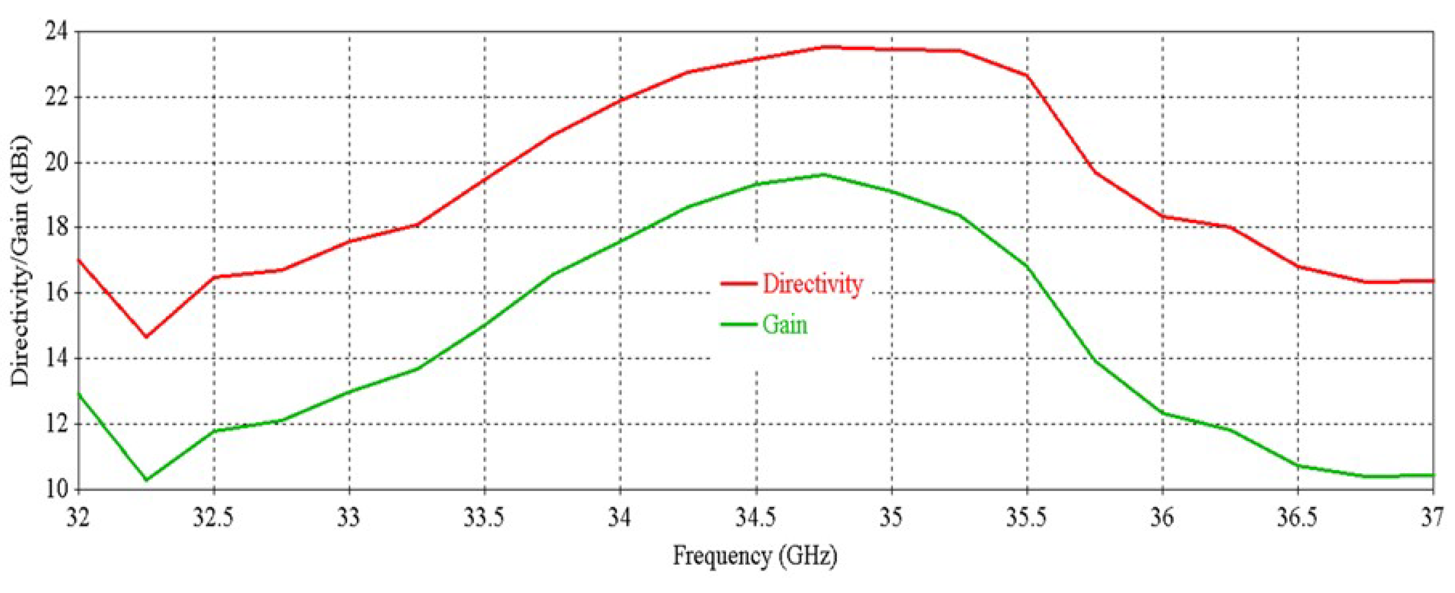
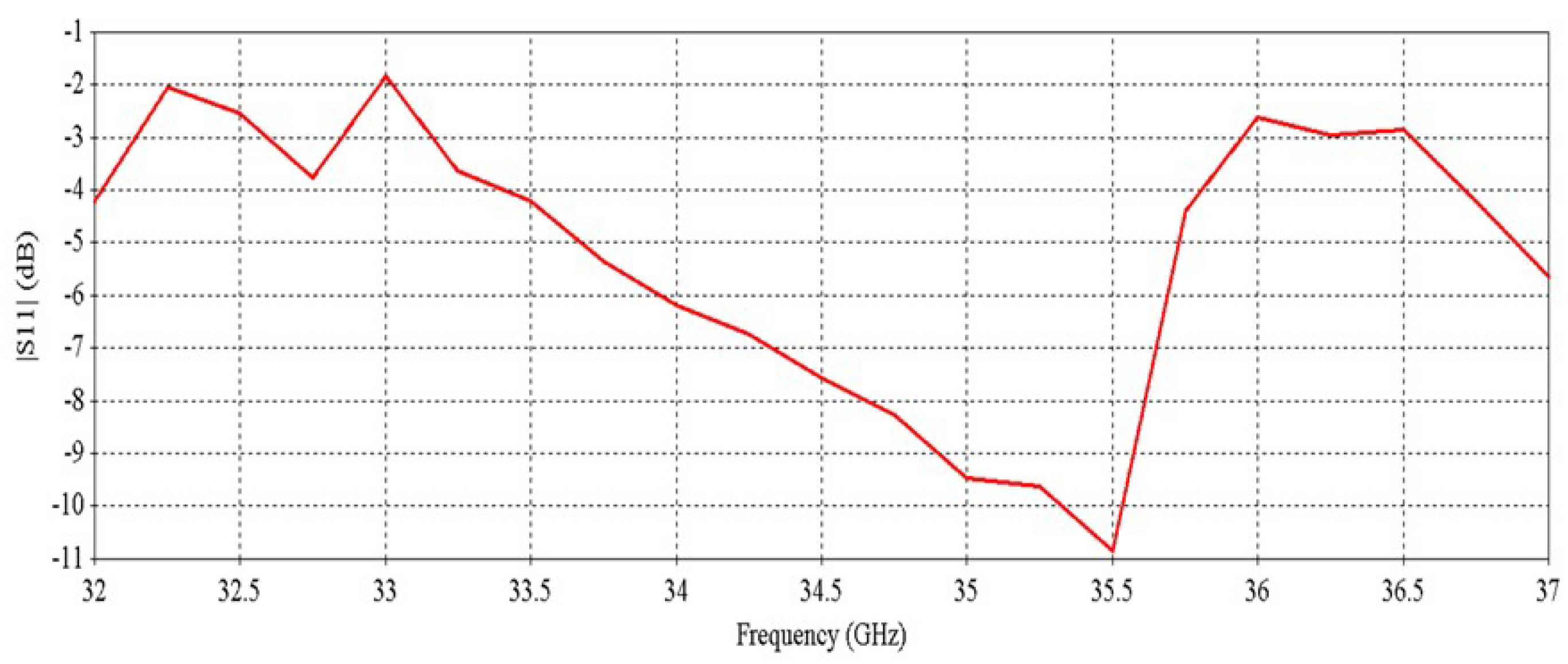
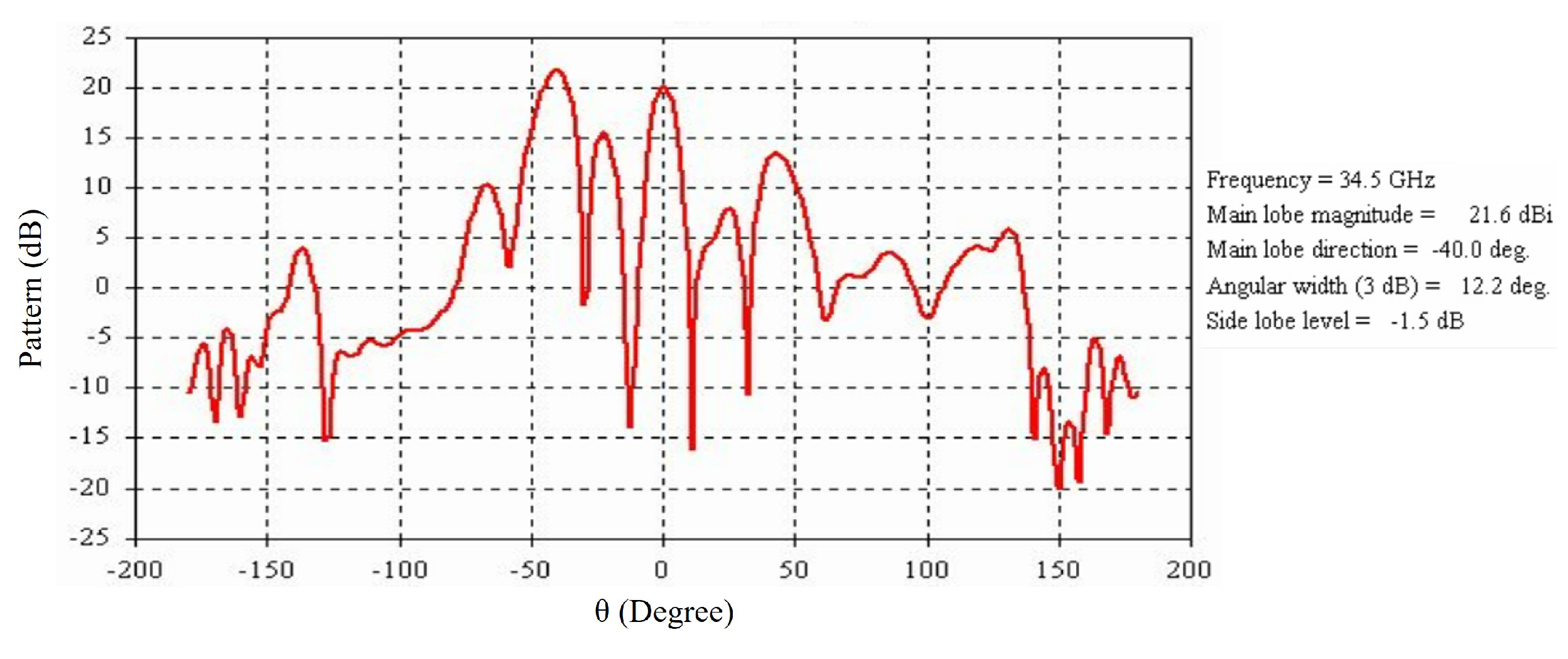
2.2. Performance Characterization
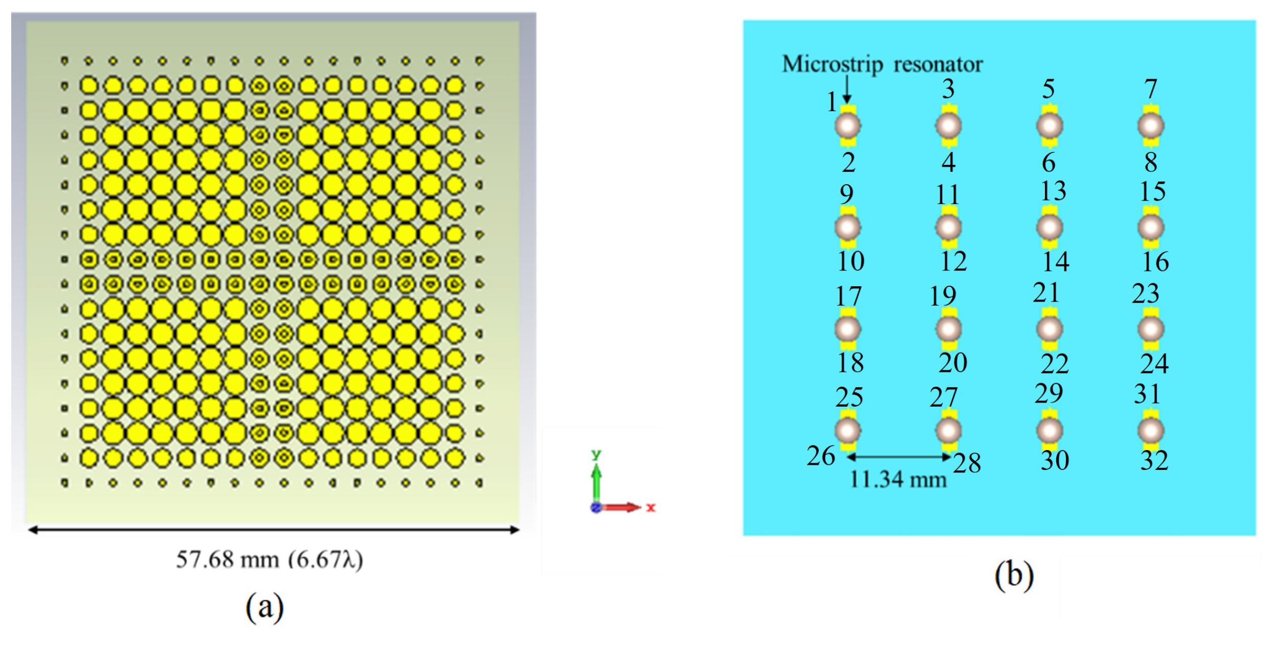
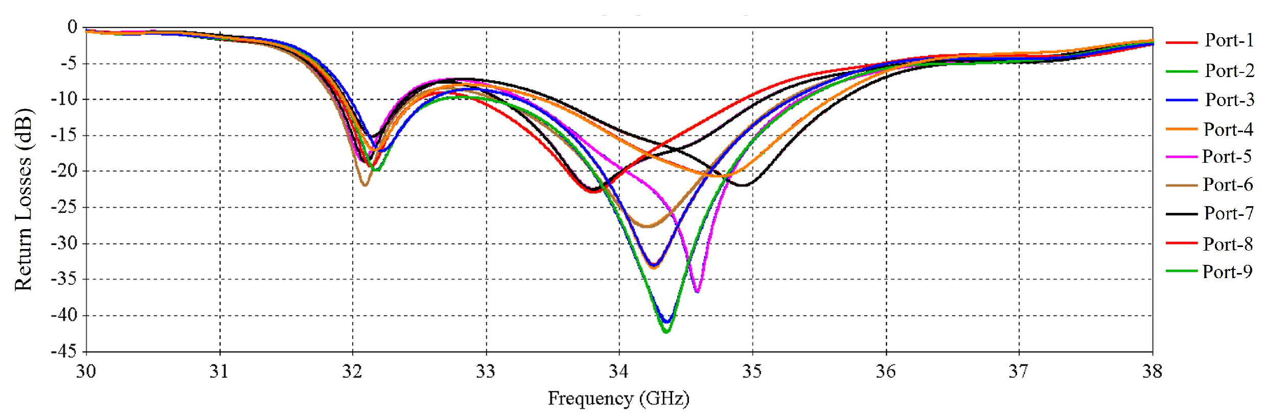
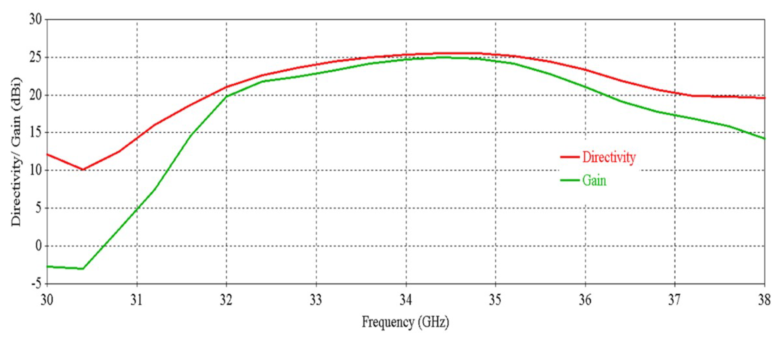
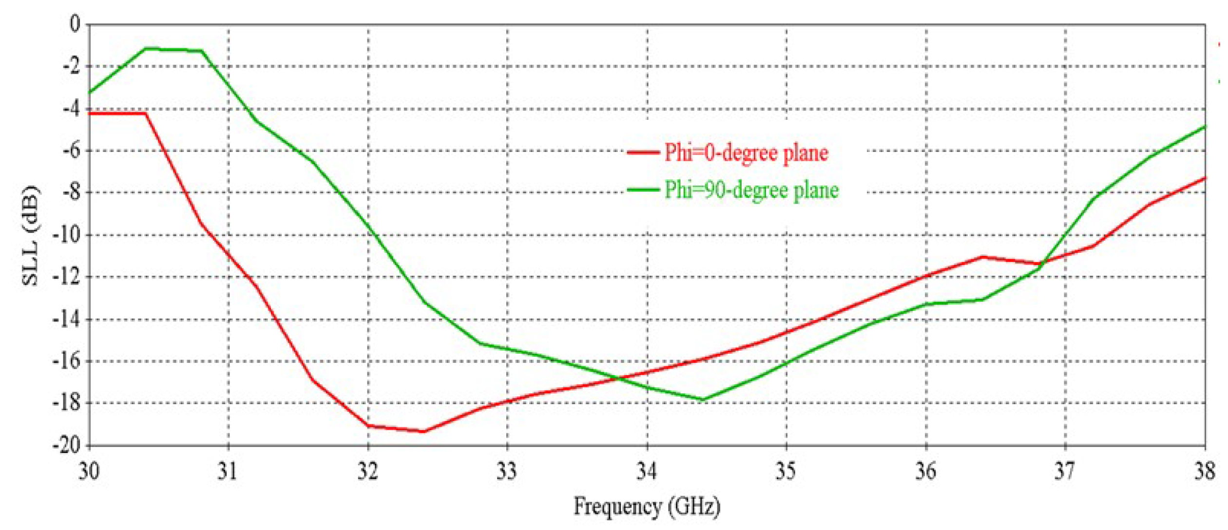
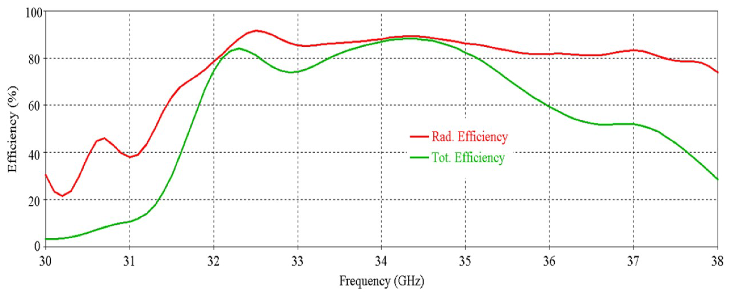
3. Phased Array Topology
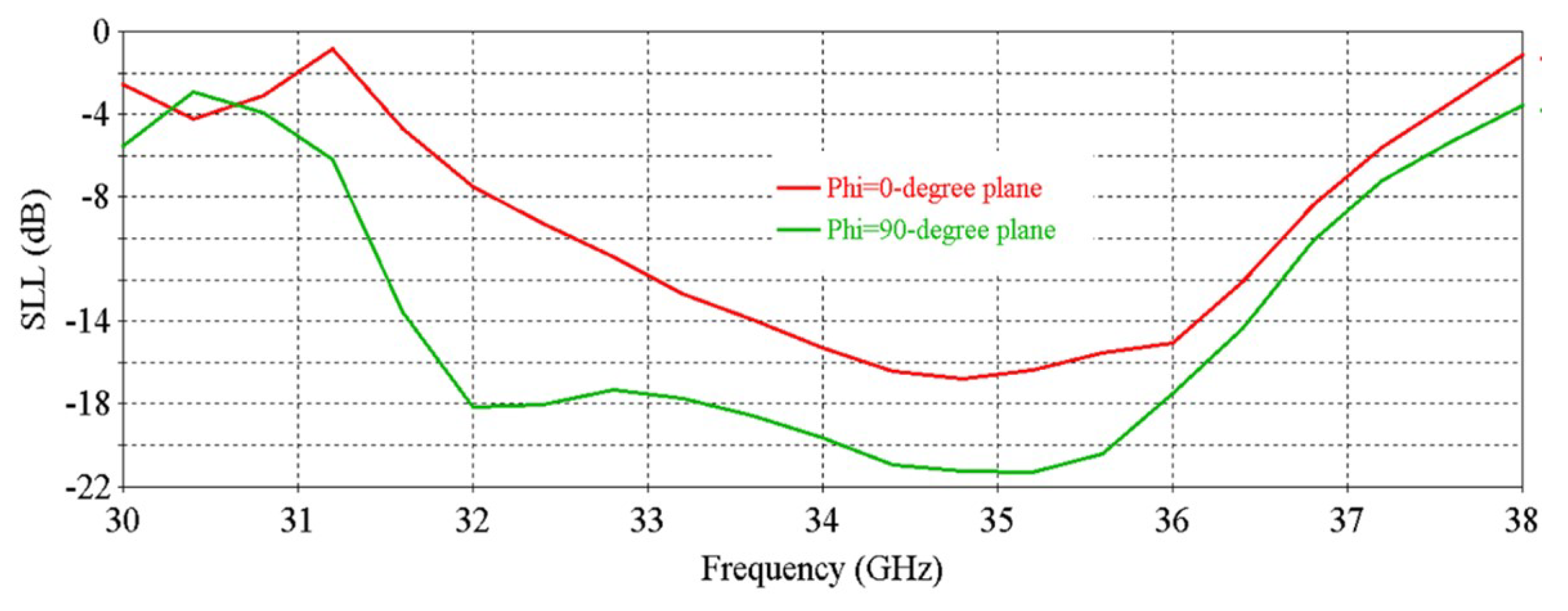
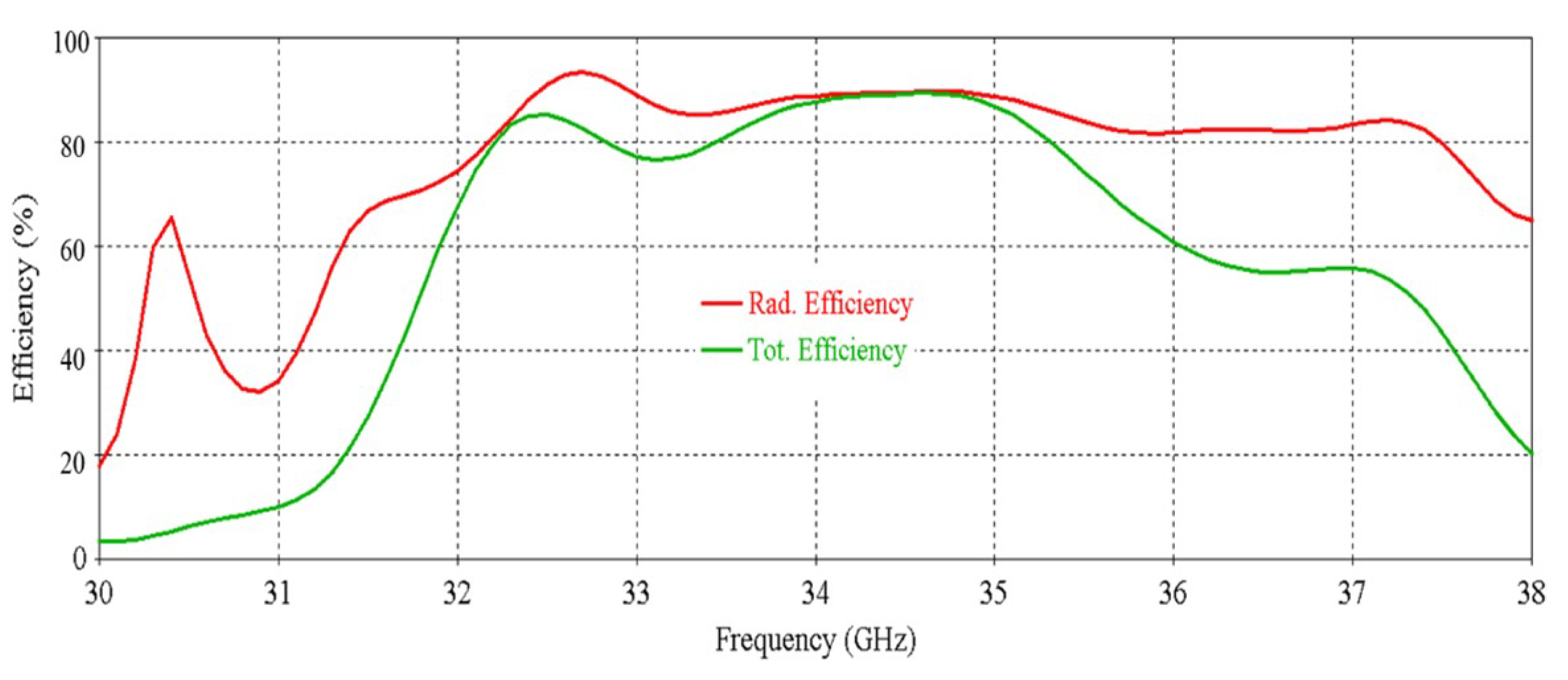
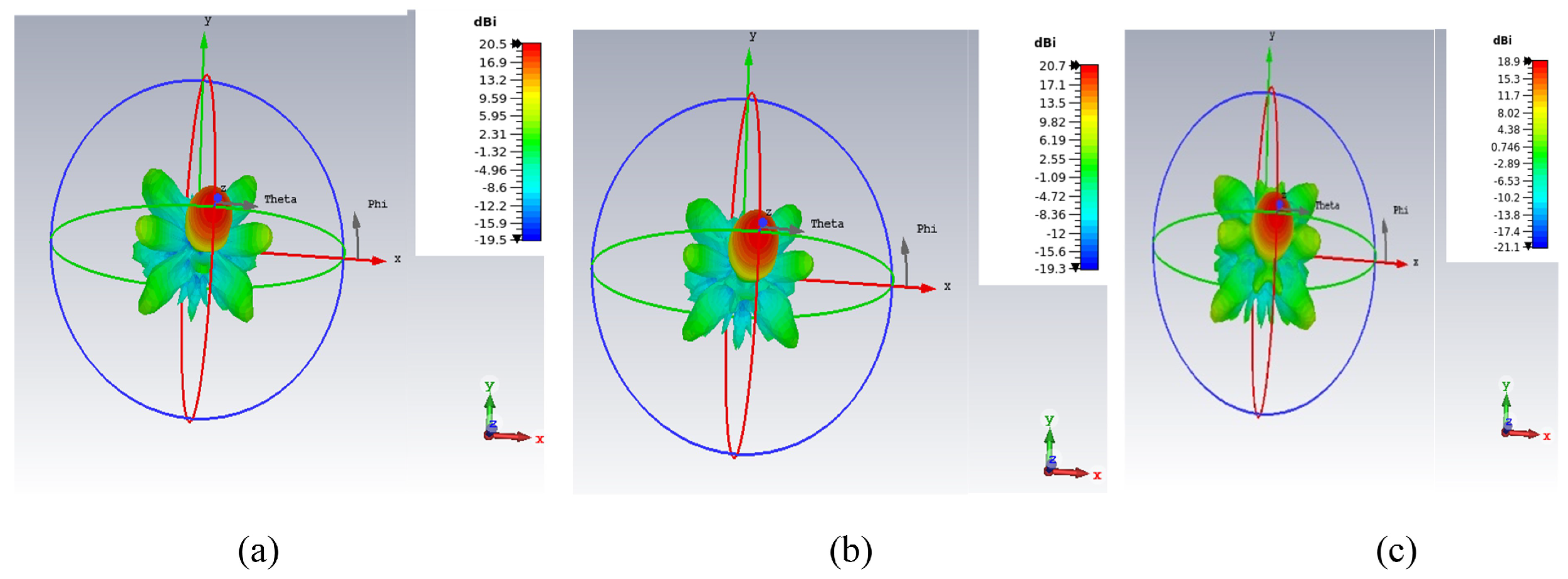
Performance of the RCA Array
4. Beam Steering Metasurface Design
4.1. Unit Cell Model
4.2. Metasurface Development from Unit Cell Model
4.3. Periodic and Aperiodic Metasurfaces Performance Comparison
5. Metasurface Optimization
5.1. Optimization Procedure
5.2. Performance Investigation of the Optimized Metasurface
6. Testing the Optimized Metasurface Performance with RCA Array
6.1. RCA Array with Maximum Beam Tilting Metasurface
6.2. RCA Array with Two Optimized Metasurfaces Aligned in Opposite Direction (0° Beam Tilting)
6.3. Performance Comparison Between Maximum and 0° Tilt for Different Metasurface Orientations
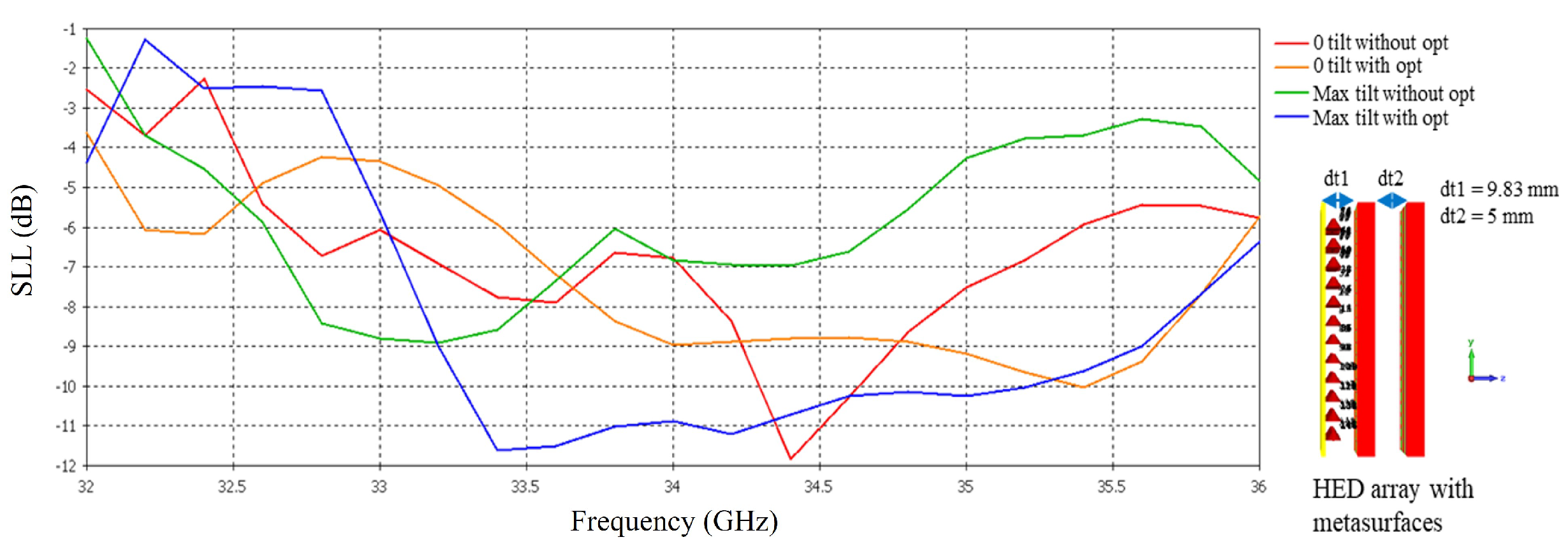
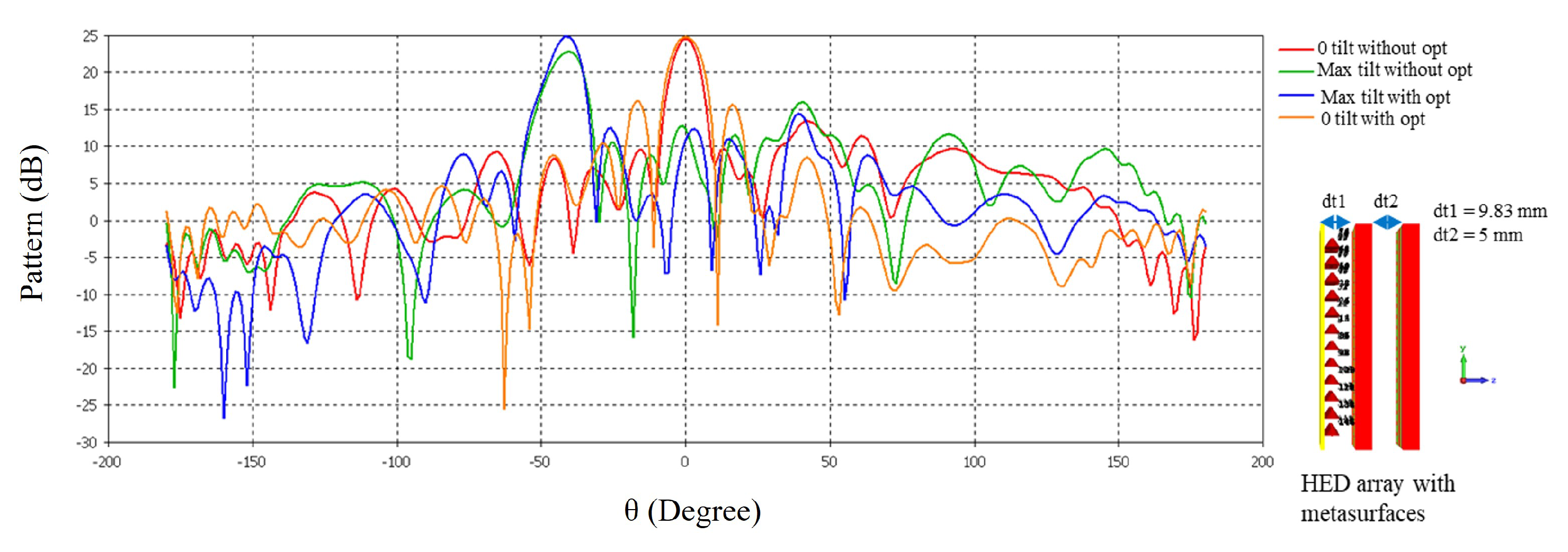
7. Antenna Performance with Closely Spaced Metasurfaces
8. Conclusions
Author Contributions
Funding
Data Availability Statement
Acknowledgments
Conflicts of Interest
References
- Deal, W.R.; Radisic, V.; Qian, Y.; Itoh, T. Integrated-antenna push-pull power amplifiers. IEEE Trans. Microw. Theory Tech. 1999, 47, 1418–1425. [Google Scholar] [CrossRef]
- Chiw, S.; Gardner, P.; Gao, S.C. Compact power combining patch antenna. Electron. Lett. 2002, 38, 1. [Google Scholar] [CrossRef]
- Duan, W.; Zhang, X.Y.; Liao, S.; Wang, K.X.; Xue, Q. Multiport power combining patch antenna with stable reflection coefficient and radiation pattern in six polarization states. IEEE Trans. Antennas Propag. 2018, 67, 719–729. [Google Scholar] [CrossRef]
- Chi, T.; Li, S.; Park, J.S.; Wang, H. A multifeed antenna for high-efficiency on-antenna power combining. IEEE Trans. Antennas Propag. 2017, 65, 6937–6951. [Google Scholar] [CrossRef]
- Marin, J.G.; Baba, A.A.; Hesselbarth, J.; Hashmi, R.M.; Esselle, K.P. Millimeter-wave low-loss multifeed superstrate-based antenna. IEEE Trans. Antennas Propag. 2020, 68, 3387–3396. [Google Scholar] [CrossRef]
- Singh, A.K.; Abegaonkar, M.P.; Koul, S.K. Wide angle beam steerable high gain flat top beam antenna using graded index metasurface lens. IEEE Trans. Antennas Propag. 2019, 67, 6334–6343. [Google Scholar] [CrossRef]
- Esselle, K.P.; Afzal, M.U.; Singh, K.; Thalakotuna, D.N.; Ahmed, F.; Sayem, A.S.M. Applications of Near-Field Meta-Steering Antenna Systems. In Proceedings of the 2021 IEEE Conference on Antenna Measurements and Applications (CAMA), Antibes Juan-les-Pins, France, 15–17 November 2021; pp. 394–397. [Google Scholar] [CrossRef]
- Afzal, M.U.; Esselle, K.P. Steering the beam of medium-to-high gain antennas using near-field phase transformation. IEEE Trans. Antennas Propag. 2017, 65, 1680–1690. [Google Scholar] [CrossRef]
- García de Blas, M.; Geday, M.A.; Otón, J.M.; Quintana Arregui, X. Two-dimensional digital beam steering based on liquid crystal phase gratings. Appl. Sci. 2021, 11, 3632. [Google Scholar] [CrossRef]
- Manzillo, F.F.; Śmierzchalski, M.; Clemente, A.; Sauleau, R. Pin diode based electronically steerable transmitarrays for SOTM at Ka-Band. In Proceedings of the 2020 14th European Conference on Antennas and Propagation (EuCAP), Copenhagen, Denmark, 15–20 March 2020; pp. 1–5. [Google Scholar]
- Diaby, F.; Clemente, A.; Sauleau, R.; Pham, K.T.; Dussopt, L. 2 bit reconfigurable unit-cell and electronically steerable transmitarray at Ka-band. IEEE Trans. Antennas Propag. 2019, 68, 5003–5008. [Google Scholar] [CrossRef]
- Lima, E.B.; Matos, S.A.; Costa, J.R.; Fernandes, C.A.; Fonseca, N.J. Circular polarization wide-angle beam steering at Ka-band by in-plane translation of a plate lens antenna. IEEE Trans. Antennas Propag. 2015, 63, 5443–5455. [Google Scholar] [CrossRef]
- Comite, D.; Kuznetcov, M.; Buendía, V.G.G.; Podilchak, S.K.; Baccarelli, P.; Burghignoli, P.; Galli, A. Directive 2-D beam steering by means of a multiport radially periodic leaky-wave antenna. IEEE Trans. Antennas Propag. 2020, 69, 2494–2506. [Google Scholar] [CrossRef]
- Debogović, T.; Perruisseau-Carrier, J. Array-fed partially reflective surface antenna with independent scanning and beamwidth dynamic control. IEEE Trans. Antennas Propag. 2013, 62, 446–449. [Google Scholar] [CrossRef]
- Song, C.; Bennett, E.L.; Xiao, J.; Jia, T.; Pei, R.; Luk, K.M.; Huang, Y. Passive beam-steering gravitational liquid antennas. IEEE Trans. Antennas Propag. 2019, 68, 3207–3212. [Google Scholar] [CrossRef]
- Cao, Y.F.; Zhang, X.Y. A wideband beam-steerable slot antenna using artificial magnetic conductors with simple structure. IEEE Trans. Antennas Propag. 2018, 66, 1685–1694. [Google Scholar] [CrossRef]
- Zhang, S.; Syrytsin, I.; Pedersen, G.F. Compact beam-steerable antenna array with two passive parasitic elements for 5G mobile terminals at 28 GHz. IEEE Trans. Antennas Propag. 2018, 66, 5193–5203. [Google Scholar] [CrossRef]
- Gagnon, N.; Petosa, A. Using rotatable planar phase shifting surfaces to steer a high-gain beam. IEEE Trans. Antennas Propag. 2013, 61, 3086–3092. [Google Scholar] [CrossRef]
- Zhao, X.; Yuan, C.; Liu, L.; Peng, S.; Zhang, Q.; Yu, L.; Sun, Y. All-metal beam steering lens antenna for high power microwave applications. IEEE Trans. Antennas Propag. 2017, 65, 7340–7344. [Google Scholar] [CrossRef]
- Yang, Y. Analytic solution of free space optical beam steering using Risley prisms. J. Light. Technol. 2008, 26, 3576–3583. [Google Scholar] [CrossRef]
- Griffiths, H.; Khan, M. Antenna beam steering technique using dielectric wedges. In IEE Proceedings H: Microwaves Antennas and Propagation; The Institution of Engineering and Technology: Stevenage, UK, 1989; Volume 136, pp. 126–131. [Google Scholar]
- Li, H.; Wang, G.; Xu, H.X.; Cai, T.; Liang, J. X-band phase-gradient metasurface for high-gain lens antenna application. IEEE Trans. Antennas Propag. 2015, 63, 5144–5149. [Google Scholar] [CrossRef]
- Ratni, B.; Merzouk, W.A.; de Lustrac, A.; Villers, S.; Piau, G.P.; Burokur, S.N. Design of phase-modulated metasurfaces for beam steering in Fabry–Perot cavity antennas. IEEE Antennas Wirel. Propag. Lett. 2016, 16, 1401–1404. [Google Scholar] [CrossRef]
- Li, J.; Zeng, Q.; Liu, R.; Denidni, T.A. Beam-tilting antenna with negative refractive index metamaterial loading. IEEE Antennas Wirel. Propag. Lett. 2017, 16, 2030–2033. [Google Scholar] [CrossRef]
- Li, T.; Chen, Z.N. Control of beam direction for substrate-integrated waveguide slot array antenna using metasurface. IEEE Trans. Antennas Propag. 2018, 66, 2862–2869. [Google Scholar] [CrossRef]
- Markovich, H.; Filonov, D.; Shishkin, I.; Ginzburg, P. Bifocal Fresnel lens based on the polarization-sensitive metasurface. IEEE Trans. Antennas Propag. 2018, 66, 2650–2654. [Google Scholar] [CrossRef]
- Hashmi, R.M.; Esselle, K.P. A class of extremely wideband resonant cavity antennas with large directivity-bandwidth products. IEEE Trans. Antennas Propag. 2015, 64, 830–835. [Google Scholar] [CrossRef]
- Baba, A.A.; Hashmi, R.M.; Esselle, K.P.; Weily, A.R. Compact high-gain antenna with simple all-dielectric partially reflecting surface. IEEE Trans. Antennas Propag. 2018, 66, 4343–4348. [Google Scholar] [CrossRef]
- Baba, A.A.; Hashmi, R.M.; Esselle, K.P.; Marin, J.G.; Hesselbarth, J. Broadband partially reflecting superstrate-based antenna for 60 GHz applications. IEEE Trans. Antennas Propag. 2019, 67, 4854–4859. [Google Scholar] [CrossRef]
- Ahmad, Z.; Hesselbarth, J. On-chip dual-polarized dielectric resonator antenna for millimeter-wave applications. IEEE Antennas Wirel. Propag. Lett. 2018, 17, 1769–1772. [Google Scholar] [CrossRef]
- Marin, J.G.; Baba, A.A.; Cuenca, D.L.; Hesselbarth, J.; Hashmi, R.M.; Esselle, K.P. High-gain low-profile chip-fed resonant cavity antennas for millimeter-wave bands. IEEE Antennas Wirel. Propag. Lett. 2019, 18, 2394–2398. [Google Scholar] [CrossRef]
- Baba, A.A.; Hashmi, R.M.; Esselle, K.P.; Attygalle, M.; Borg, D. A millimeter-wave antenna system for wideband 2-D beam steering. IEEE Trans. Antennas Propag. 2020, 68, 3453–3464. [Google Scholar] [CrossRef]
- Singh, K.; Afzal, M.U.; Kovaleva, M.; Esselle, K.P. Controlling the most significant grating lobes in two-dimensional beam-steering systems with phase-gradient metasurfaces. IEEE Trans. Antennas Propag. 2019, 68, 1389–1401. [Google Scholar] [CrossRef]
- Naqvi, A.H.; Lim, S. A beam-steering antenna with a fluidically programmable metasurface. IEEE Trans. Antennas Propag. 2019, 67, 3704–3711. [Google Scholar] [CrossRef]
- Afzal, M.U.; Matekovits, L.; Esselle, K.P.; Lalbakhsh, A. Beam-scanning antenna based on near-electric field phase transformation and refraction of electromagnetic wave through dielectric structures. IEEE Access 2020, 8, 199242–199253. [Google Scholar] [CrossRef]
- Ahmed, F.; Hayat, T.; Afzal, M.U.; Zhang, S.; Esselle, K.P.; Whittow, W.G. 3-D printable synthetic metasurface to realize 2-D beam-steering antenna. IEEE Open J. Antennas Propag. 2023, 4, 506–519. [Google Scholar] [CrossRef]


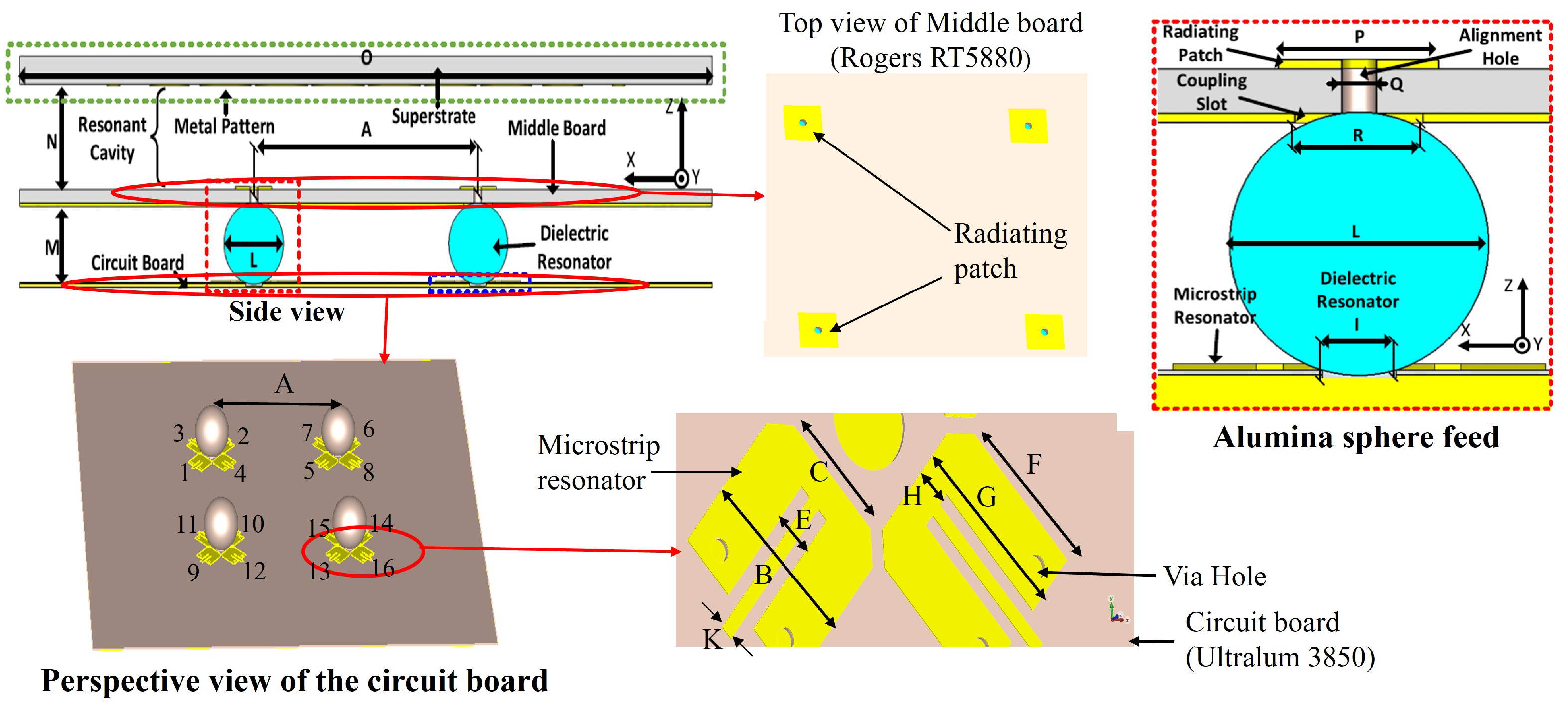
| Parameter | Value (mm) | Parameter | Value (mm) | Parameter | Value (mm) |
|---|---|---|---|---|---|
| A | 11.314 | B | 1.575 | C | 1.138 |
| E | 0.375 | F | 1.3735 | G | 1.592 |
| H | 0.31 | I | 0.85 | J | 1.338 |
| K | 0.125 | L | 3 | M | 2.82 |
| N | 3.92 | O | 35 | P | 1.8546 |
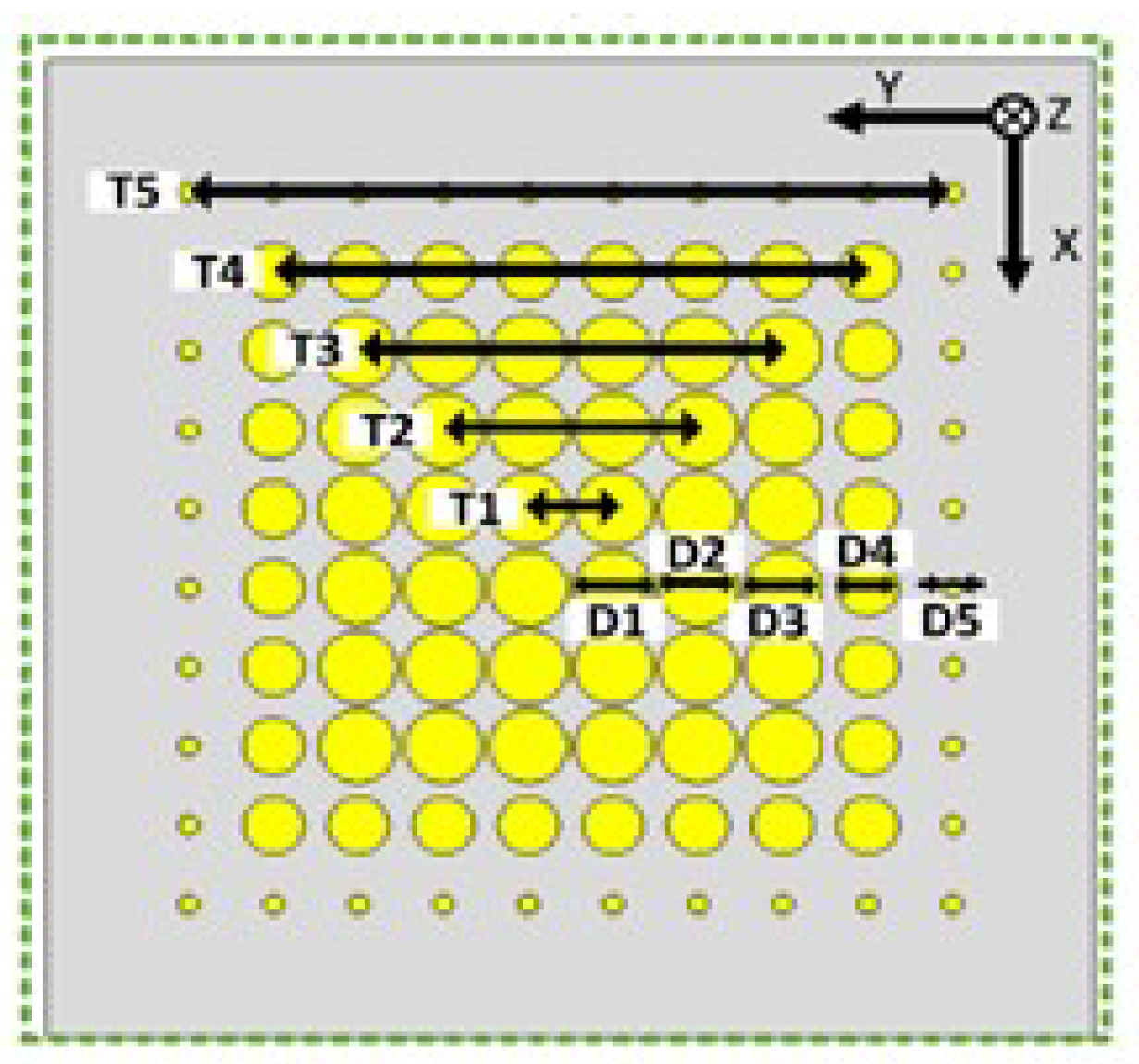
| Q | 0.4 | R | 1.48 | D1 | 2.667 |
| D2 | 2.663 | D3 | 2.62 | D4 | 2.04 |
| D5 | 0.68 | T1 | 2.835 | T2 | 8.506 |
| T3 | 14.176 | T4 | 19.847 | T5 | 25.517 |
| Material | Dielectric Constant | Loss Tangent | Component | Thickness/Diameter (mm) |
|---|---|---|---|---|
| Alumina | 9.98 | 0.0002 | Sphere | 3 |
| Ultralum 3850 | 2.9 | 0.0025 | Circuit board | 0.05 |
| Rogers RT5880 | 2.2 | 0.0009 | Middleboard | 0.508 |
| TMM4 | 4.7 | 0.002 | Superstrate | 1.03 |
| Configuration | SLL (dB) | Directivity (dB) |
|---|---|---|
| HED array only | −13.2 | 26.7 |
| One periodic metasurface | −9.5 | 25.9 |
| One aperiodic metasurface | −7.4 | 24.9 |
| Two periodic metasurfaces aligned in the same direction | −4 | 21.9 |
| Two aperiodic metasurfaces aligned in the same direction | −3.4 | 21.7 |
| Two periodic metasurfaces aligned in the opposite direction | −6.1 | 24.1 |
| Two aperiodic metasurfaces aligned in the opposite direction | −5.5 | 23.1 |
| Cell | Hole Radius (mm) Before Optimization | Hole Radius (mm) After Optimization | % Change |
|---|---|---|---|
| 1 | 0.55 | 0.61 | 10.91 |
| 2 | 0.75 | 1.07 | 42.67 |
| 3 | 0.94 | 1.26 | 34.04 |
| 4 | 0.56 | 0.96 | 71.42 |
| 5 | 0.91 | 1.2 | 31.87 |
| 6 | 0.62 | 0.94 | 51.61 |
| 7 | 0.94 | 1.4 | 48.94 |
| 8 | 0.81 | 1.3 | 60.49 |
| 9 | 1.22 | 1.4 | 14.75 |
| Ref | Freq (GHz) | Steering Technique | Scanning Angle (°) | Peak Gain (dBi) | DC Power |
|---|---|---|---|---|---|
| [8] | 11 | Mechanical | ±46 | 19.4 | No |
| [16] | 5.5 | PIN Diode | ±36 | 7 | Low |
| [19] | 9.375 | Mechanical | ±20 | - | No |
| [32] | 35 | Mechanical | ±40 | 21.5 | No |
| [34] | 2.62 | Water | ±20 | 5.7 | No |
| [35] | 30 | Mechanical | ±39 | 16 | No |
| [36] | 11 | Mechanical | ±57 | 19.9 | No |
| This work | 35 | Mechanical | ±40 | 25.03 | No |
Disclaimer/Publisher’s Note: The statements, opinions and data contained in all publications are solely those of the individual author(s) and contributor(s) and not of MDPI and/or the editor(s). MDPI and/or the editor(s) disclaim responsibility for any injury to people or property resulting from any ideas, methods, instructions or products referred to in the content. |
© 2025 by the authors. Licensee MDPI, Basel, Switzerland. This article is an open access article distributed under the terms and conditions of the Creative Commons Attribution (CC BY) license (https://creativecommons.org/licenses/by/4.0/).
Share and Cite
Sayem, A.S.M.; Esselle, K.P.; Thalakotuna, D.N.; Attygalle, M.; Singh, K. Designing Chip-Feed High-Gain Millimeter-Wave Resonant Cavity Antenna (RCA) Array and Optimization of Beam Steering Metasurface. Micromachines 2025, 16, 164. https://doi.org/10.3390/mi16020164
Sayem ASM, Esselle KP, Thalakotuna DN, Attygalle M, Singh K. Designing Chip-Feed High-Gain Millimeter-Wave Resonant Cavity Antenna (RCA) Array and Optimization of Beam Steering Metasurface. Micromachines. 2025; 16(2):164. https://doi.org/10.3390/mi16020164
Chicago/Turabian StyleSayem, Abu Sadat Md., Karu P. Esselle, Dushmantha N. Thalakotuna, Manik Attygalle, and Khushboo Singh. 2025. "Designing Chip-Feed High-Gain Millimeter-Wave Resonant Cavity Antenna (RCA) Array and Optimization of Beam Steering Metasurface" Micromachines 16, no. 2: 164. https://doi.org/10.3390/mi16020164
APA StyleSayem, A. S. M., Esselle, K. P., Thalakotuna, D. N., Attygalle, M., & Singh, K. (2025). Designing Chip-Feed High-Gain Millimeter-Wave Resonant Cavity Antenna (RCA) Array and Optimization of Beam Steering Metasurface. Micromachines, 16(2), 164. https://doi.org/10.3390/mi16020164