
Batch Fine Magnetic Pattern Transfer Method on Permanent Magnets Using Coercivity Change during Heating for Magnetic MEMS

Abstract
1. Introduction
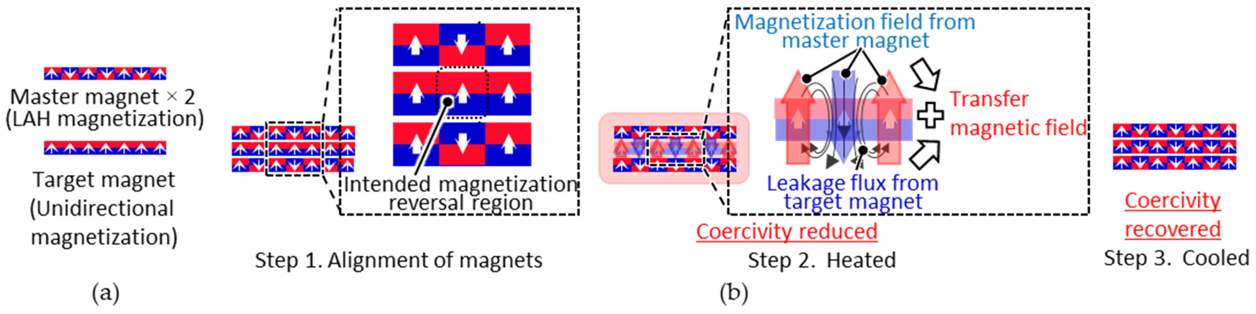
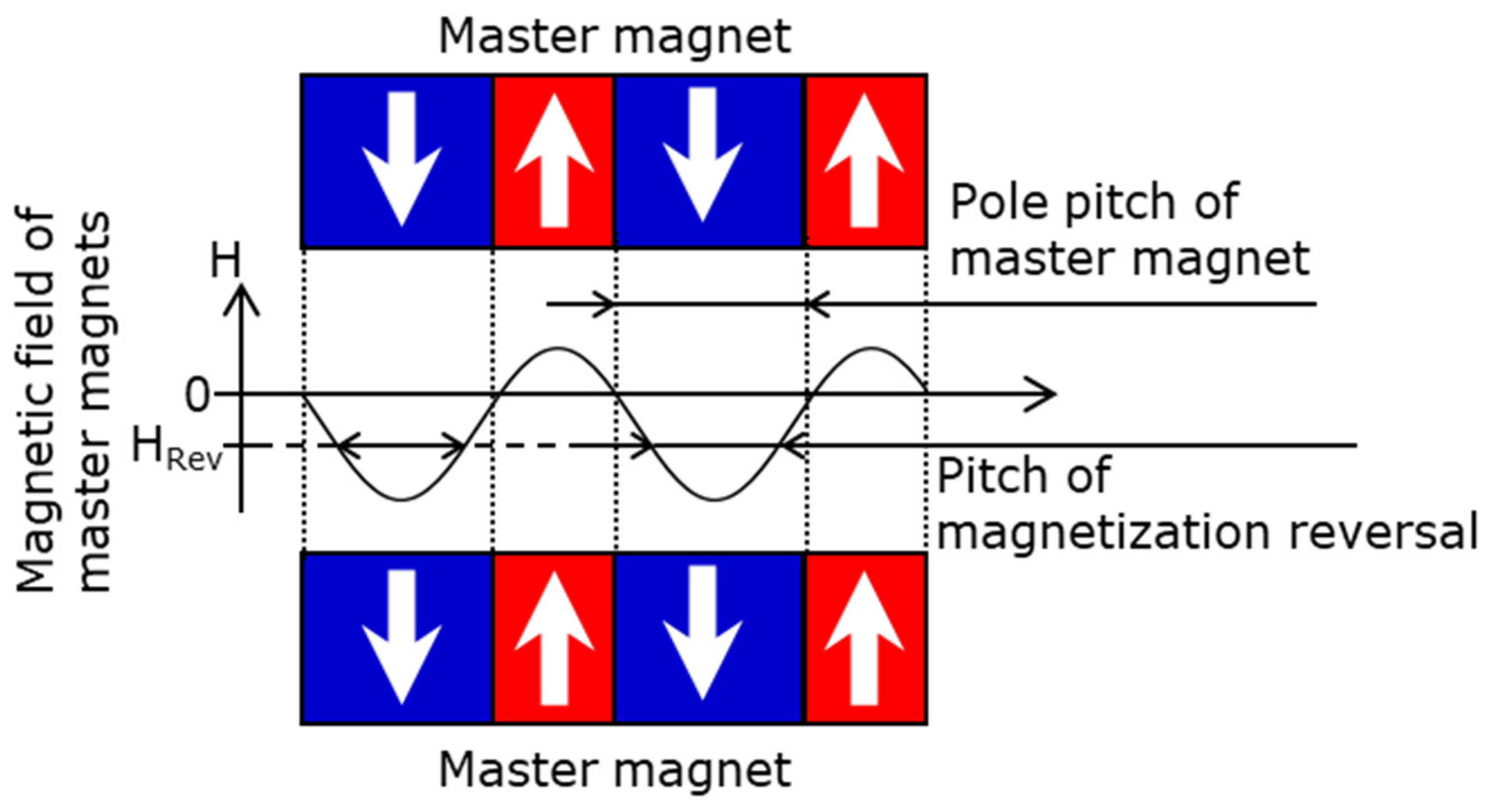
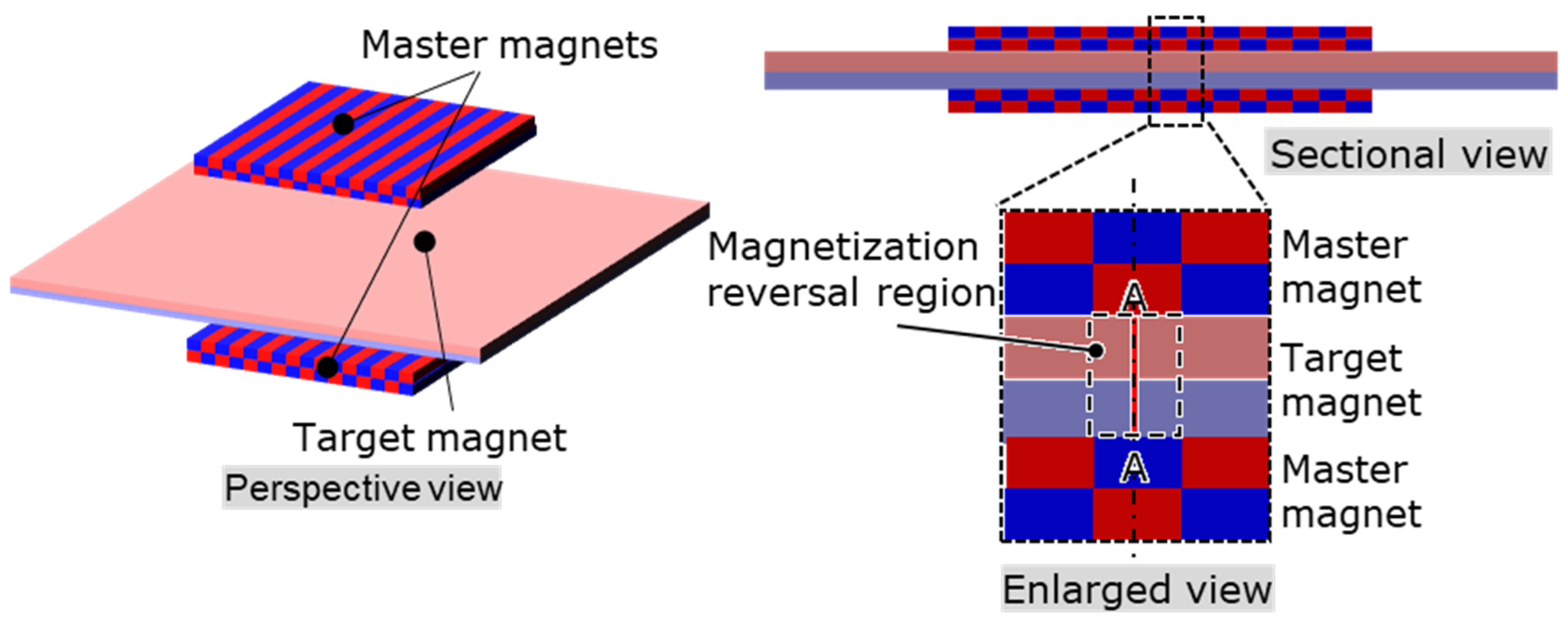
2. MPT Method
3. Experimental Methods
3.1. Master Magnet Design
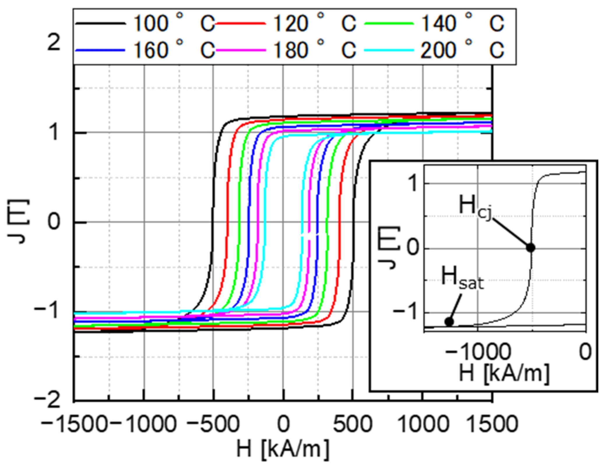
3.1.1. Selection of the Master Magnet Material and LAH Magnetization Conditions
3.1.2. Master Magnet Fabrication
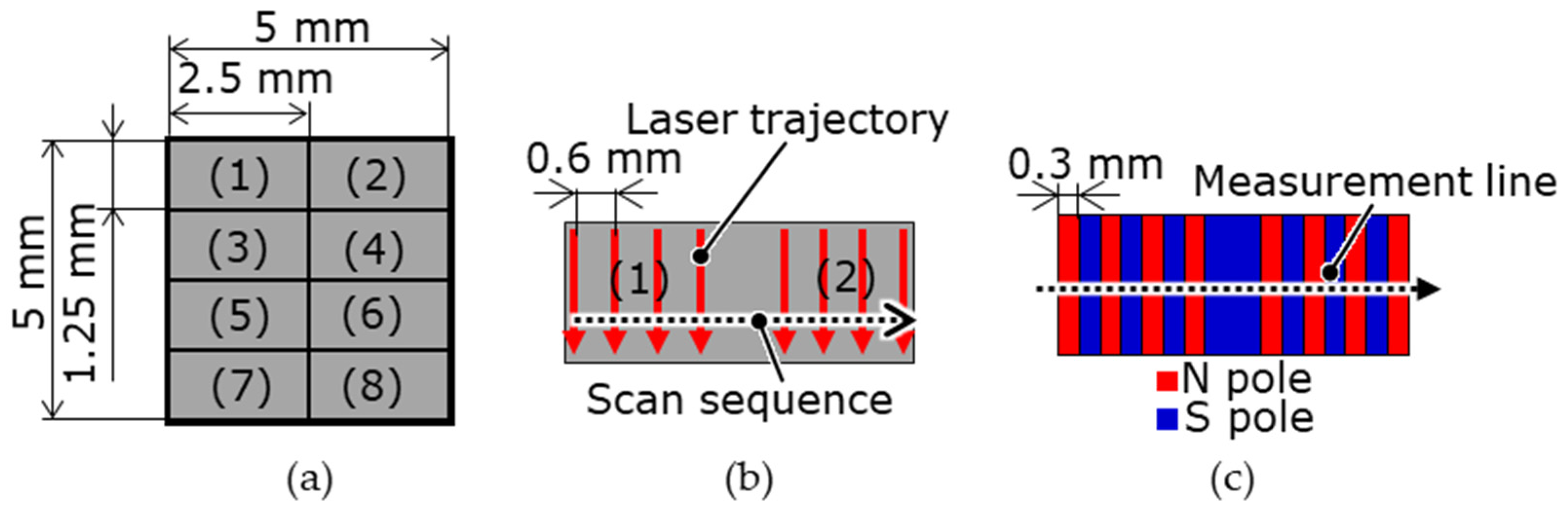
3.2. MPT TEST
4. Experimental Results and Discussion
4.1. Experimental Master Magnet and LAH Magnetization Conditions
4.2. Master Magnet Fabrication Results
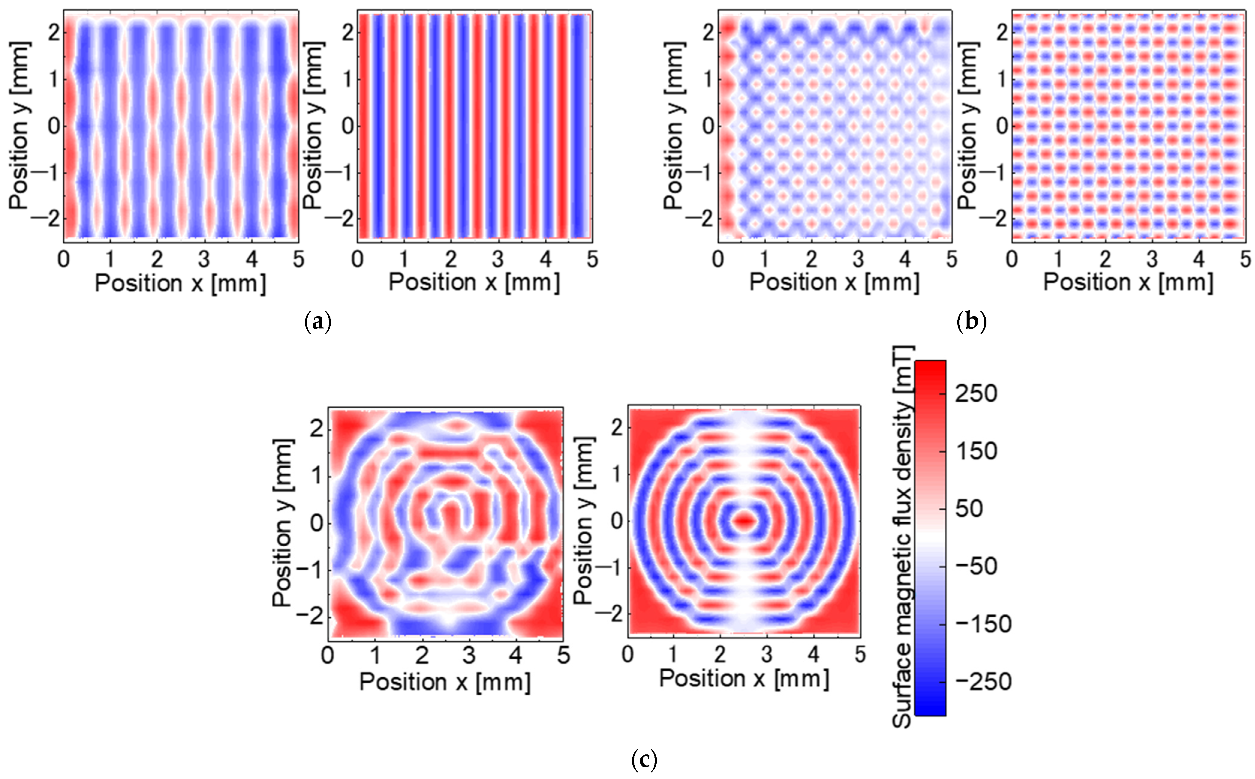
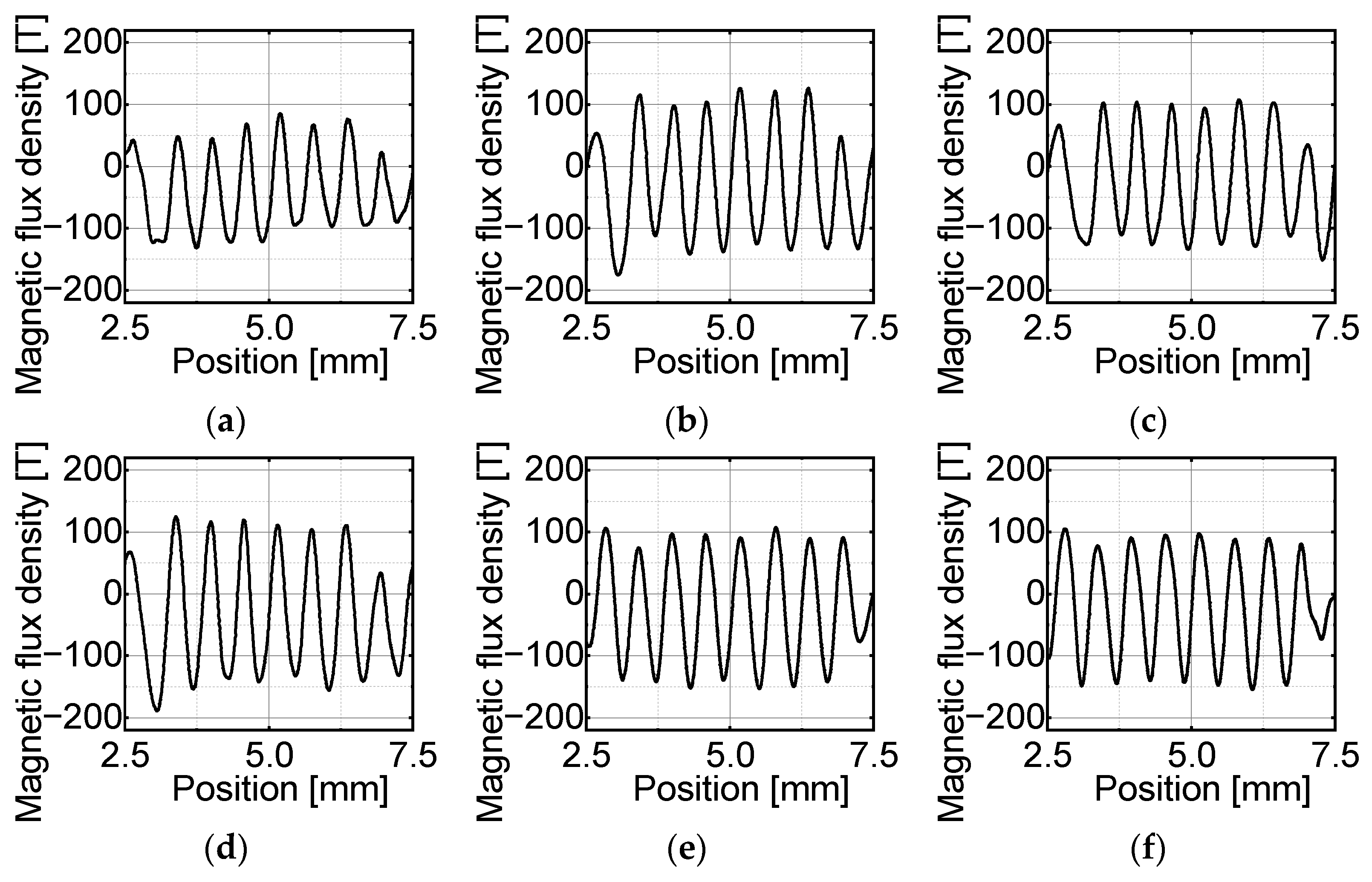
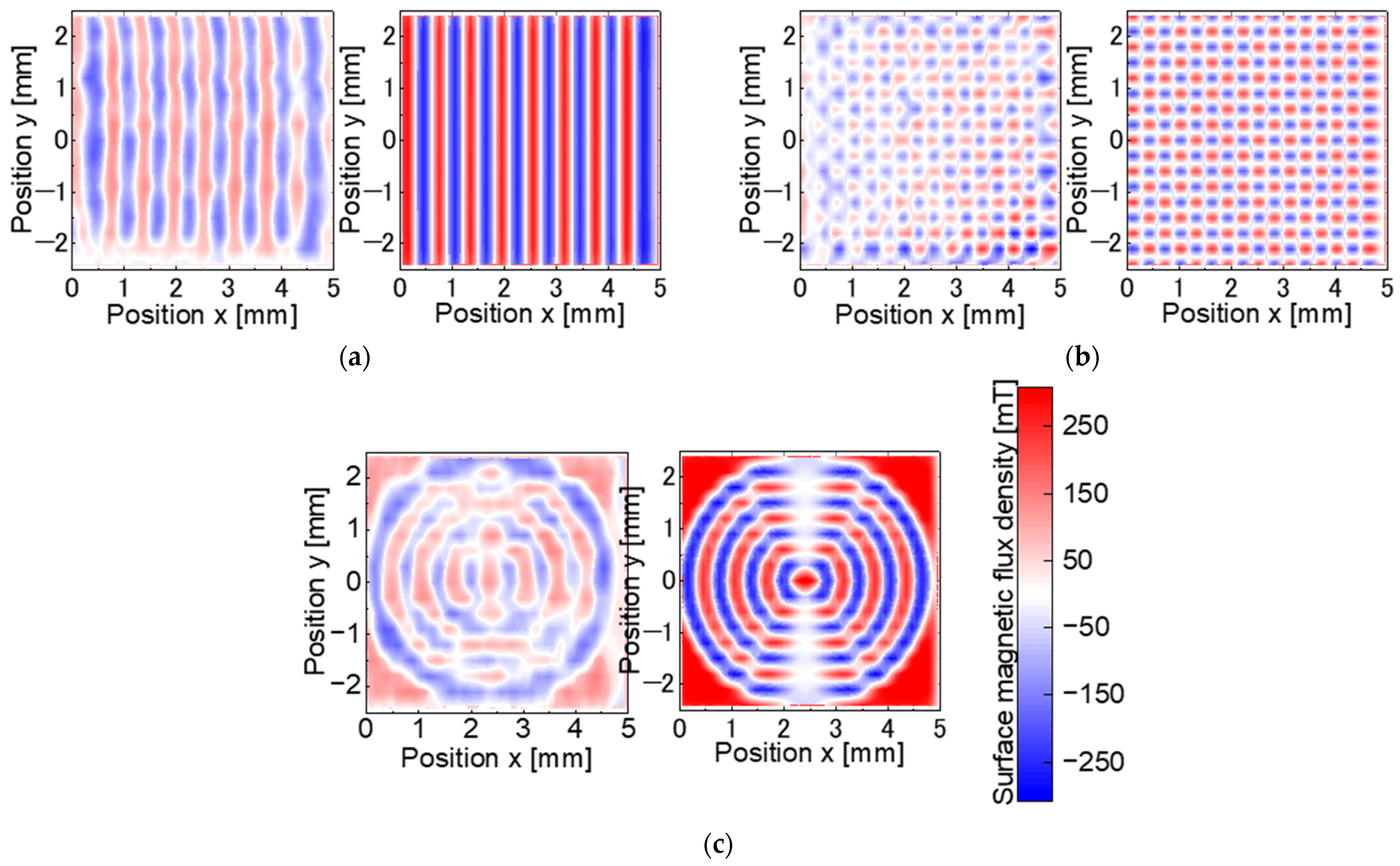
4.3. Magnetic Pattern Transfer Results
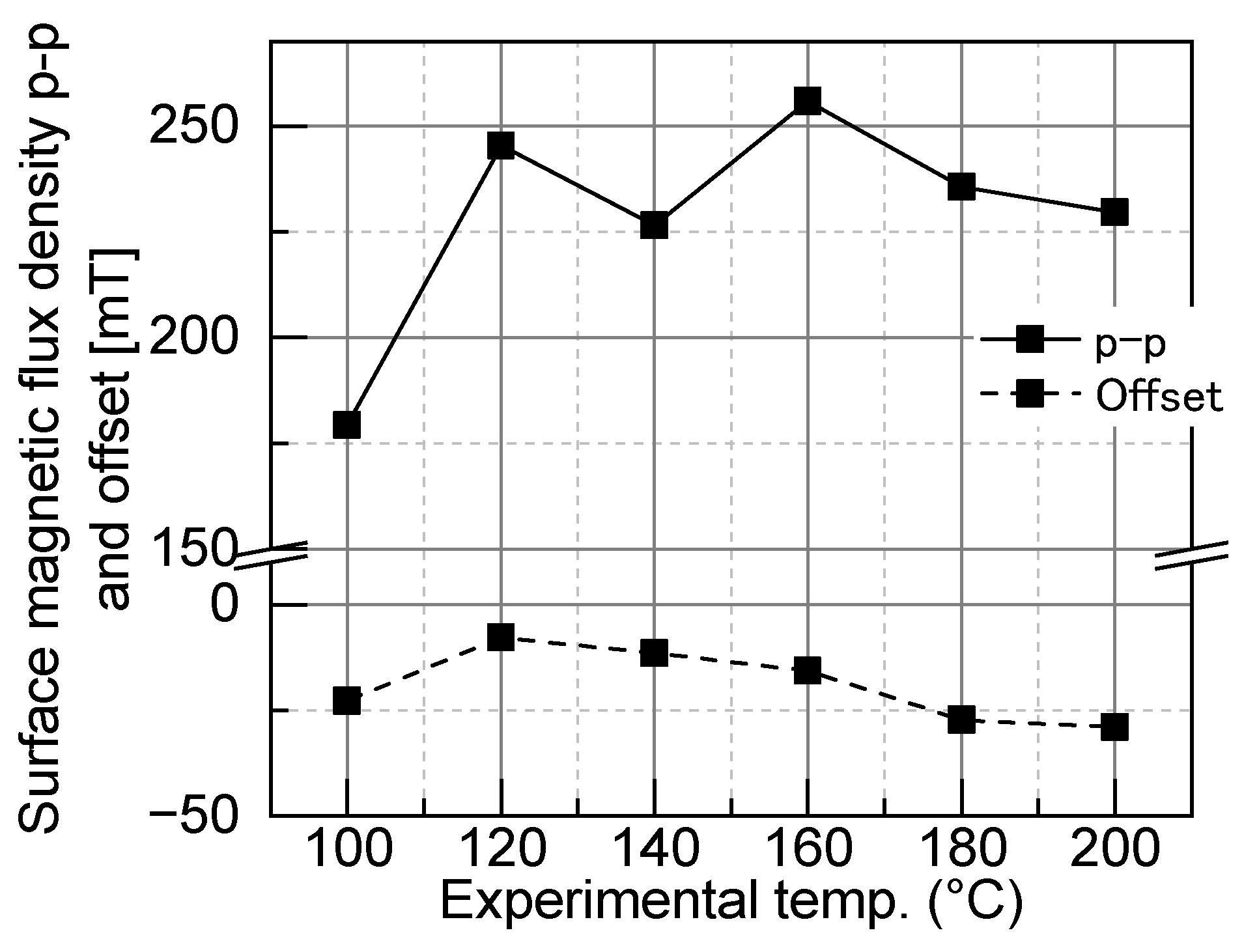
4.4. Discussion of the Magnetic Pattern Transfer
5. Conclusions
Author Contributions
Funding
Data Availability Statement
Acknowledgments
Conflicts of Interest
References
- Raeesi, A.; Al-Saedi, H.; Palizban, A.; Taeb, A.; Abdel-Wahab, W.M.; Gigoyan, S.; Safavi-Naeini, S. Low-cost planar RF MEMS-based attenuator. IEEE MTT-S Int. Microw. Symp. Dig. 2019, 2019, 869–872. [Google Scholar]
- Nishibe, Y.; Nonomura, Y.; Tsukada, K.; Takeuchi, M.; Miyashita, M.; Ito, K. Determination of engine misfiring using magnetoelastic torque sensor. IEEE Trans. Instrum. Meas. 1998, 47, 760–765. [Google Scholar] [CrossRef]
- Niclass, C.; Ito, K.; Soga, M.; Matsubara, H.; Aoyagi, I.; Kato, S.; Kagami, M. Design and characterization of a 256x64-pixel single-photon imager in CMOS for a MEMS-based laser scanning time-of-flight sensor. Opt. Express 2012, 20, 11863–11881. [Google Scholar] [CrossRef]
- Gao, L.; Xu, X.; Li, S.; Xu, D.; Yao, Y. Micro acceleration measurement system based on highly-sensitive tunnel magneto-resistance sensor. In Proceedings of the 2019 IEEE International Symposium on Inertial Sensors and Systems (INERTIAL), Naples, FL, USA, 1–5 April 2019; pp. 1–4. [Google Scholar] [CrossRef]
- Ye, L.; Zhang, G.; You, Z. Large-aperture kHz operating frequency Ti-alloy based optical micro scanning mirror for LiDAR application. Micromachines 2017, 8, 120. [Google Scholar] [CrossRef]
- Hoang, M.L.; Pietrosanto, A. Yaw/heading optimization by machine learning model based on MEMS magnetometer under harsh conditions. Measurement 2022, 193, 111013. [Google Scholar] [CrossRef]
- Kim, K.H.; Park, B.H.; Maguluri, G.N.; Lee, T.W.; Rogomentich, F.J.; Bancu, M.G.; Bouma, B.E.; de Boer, J.F.; Bernstein, J.J. Two-axis magnetically-driven MEMS scanning catheter for endoscopic high-speed optical coherence tomography. Opt. Express 2007, 15, 18130–18140. [Google Scholar] [CrossRef] [PubMed]
- Searles, K.; Shalabi, N.; Jayhooni, S.M.H.; Takahata, K. A planar micro rotary actuator for endoscopic optical scanning. Sens. Actuators A Phys. 2022, 345, 113768. [Google Scholar] [CrossRef]
- Indianto, M.A.; Toda, M.; Ono, T. Comprehensive study of magnetostriction-based MEMS magnetic sensor of a FeGa/PZT cantilever. Sens. Actuators A Phys. 2021, 331, 112985. [Google Scholar] [CrossRef]
- Javor, J.; Stange, A.; Pollock, C.; Fuhr, N.; Bishop, D.J. 100 pT/cm single-point MEMS magnetic gradiometer from a commercial accelerometer. Microsyst. Nanoeng. 2020, 6, 71. [Google Scholar] [CrossRef] [PubMed]
- Yunas, J.; Mulyanti, B.; Hamidah, I.; Said, M.M.; Pawinanto, R.E.; Ali, W.A.F.W.; Subandi, A.; Hamzah, A.A.; Latif, R.; Majlis, B.Y. Polymer-based MEMS electromagnetic actuator for biomedical application: A review. Polymers 2020, 12, 1184. [Google Scholar] [CrossRef] [PubMed]
- Bodduluri, M.T.; Gojdka, B.; Wolff, N.; Kienle, L.; Lisec, T.; Lofink, F. Investigation of wafer-level fabricated permanent micromagnets for MEMS. Micromachines 2022, 13, 742. [Google Scholar] [CrossRef]
- Guan, S.; Nelson, B.J. Fabrication of hard magnetic microarrays by electroless codeposition for MEMS actuators. Sens. Actuators A Phys. 2005, 118, 307–312. [Google Scholar] [CrossRef]
- Lisec, T.; Bodduluri, M.T.; Schulz-Walsemann, A.-V.; Blohm, L.; Pieper, I.; Gu-Stoppel, S.; Niekiel, F.; Lofink, F.; Wagner, B. Integrated high power micro magnets for MEMS sensors and actuators. In Proceedings of the 2019 20th International Conference on Solid-State Sensors, Actuators and Microsystems & Eurosensors XXXIII (TRANSDUCERS & EUROSENSORS XXXIII), Berlin, Germany, 23–27 June 2019; pp. 1768–1771. [Google Scholar] [CrossRef]
- Nakano, M.; Takeichi, S.; Takashima, K.; Yamashita, A.; Yanai, T.; Fukunaga, H. Preparation and deposition of Pr–Fe–B permanent-magnet powder using pulsed laser. IEEE Trans. Magn. 2020, 56, 1–3. [Google Scholar] [CrossRef]
- Yamaguchi, H.; Higuchi, K.; Kaku, H.; Yamashita, A.; Yanai, T.; Fukunaga, H.; Nagai, K.; Shinshi, T.; Nakano, M. Nd-Fe-B thick-film magnets on Si substrates with Al-O underlayers. IEEE Trans. Magn. 2023, 59, 1–4. [Google Scholar] [CrossRef]
- Han, D.; Shinshi, T.; Azuma, N.; Kadota, S. An in-plane, large-stroke, multipole electromagnetic microactuator realized by guideways stacking mechanism. Sens. Actuators A Phys. 2019, 298, 111563. [Google Scholar] [CrossRef]
- Zhi, C.; Shinshi, T.; Saito, M.; Kato, K. Planar-type micro-electromagnetic actuators using patterned thin film permanent magnets and mesh type coils. Sens. Actuators A Phys. 2014, 220, 365–372. [Google Scholar] [CrossRef]
- Wang, Y.; Zhi, C.; Tang, B.; Yang, K.; Xie, J.; Xu, W.; Li, H.; Wang, X. A micro electromagnetic actuator with high force density. Sens. Actuators A Phys. 2021, 331, 112771. [Google Scholar] [CrossRef]
- Qi, C.; Han, D.; Shinshi, T. A MEMS-based electromagnetic membrane actuator utilizing bonded magnets with large displacement. Sens. Actuators A Phys. 2021, 330, 112834. [Google Scholar] [CrossRef]
- Tao, K.; Wu, J.; Kottapalli, A.G.P.; Chen, D.; Yang, Z.; Ding, G.; Lye, S.W.; Miao, J. Micro-patterning of resin-bonded NdFeB magnet for a fully integrated electromagnetic actuator. Solid-State Electron. 2017, 138, 66–72. [Google Scholar] [CrossRef]
- Han, M.; Yuan, Q.; Sun, X.; Zhang, H. Design and fabrication of integrated magnetic MEMS energy harvester for low frequency applications. J. Microelectromech. Syst. 2014, 23, 204–212. [Google Scholar] [CrossRef]
- Fujiwara, R.; Tanaka, S.; Hijikata, W.; Shinshi, T. Sub-millimeter pitch multi-pole magnetization in a sintered Nd-Fe-B magnet utilizing laser heating. IEEE Magn. Lett. 2016, 7, 1–4. [Google Scholar] [CrossRef]
- Han, D.; Nagai, K.; Shinshi, T. High torque micro slice motor using a multipole ring magnet. Sens. Actuators A Phys. 2020, 311, 112050. [Google Scholar] [CrossRef]
- Komura, H.; Kitaoka, M.; Kiyomiya, T.; Matsuo, Y. Fine pole-pitch magnetizing method for Nd–Fe–B isotropic magnet with high coercivity. J. Appl. Phys. 2007, 101, 09K104. [Google Scholar] [CrossRef]
- Komura, H.; Kitaoka, M.; Kiyomiya, T.; Matsuo, Y. Establishment of multi-pole magnetizing method and apparatus using a heating system for Nd-Fe-B isotropic bonded magnets. IEEE Trans. Magn. 2008, 44, 4266–4268. [Google Scholar] [CrossRef]


| Magnet Type | Residual Flux Density Br [T] | Coercivity Hc [kA/m] | Intrinsic Coercivity Hcj [kA/m] | Temperature Coefficient [%/°C] | |
|---|---|---|---|---|---|
| Br | Hcj | ||||
| NdFeB N38EH | 1.24 | 907 | 2388 | −0.04 | −0.2 |
| SmCo SS30H | 1.09 | 830 | 1990 | −0.03 | −0.15 |
| Laser Type | Repetition Frequency [kHz] | Spot Diameter [mm] | Scan Pitch [mm] | Laser Power [W] | Scanning Speed [mm/s] | External Mag. Field [T] |
|---|---|---|---|---|---|---|
| YVO4 532 nm | 30 | 0.1 | 0.6 | 6 | 100–200 | 0.7, 0.9 |
| Magnet Type | Residual Flux Density Br [T] | Coercivity Hc [kA/m] | Intrinsic Coercivity Hcj [kA/m] | Temperature Coefficient [%/°C] | |
|---|---|---|---|---|---|
| Br | Hcj | ||||
| NdFeB N35 | 1.20 | 870 | 955 | −0.12 | −0.55 |
| Density [kg/m3] | Thermal Expansion Coefficient [kA/m] | Young’s Modulus [GPa] | Poisson’s Ratio | Thermal Conductivity [W/m K] | Specific Heat Capacity [J/kg K] | |
|---|---|---|---|---|---|---|
| SmCo | 8400 | C⊥ 1.0 × 10⁻⁵ C// 8.0 × 10⁻⁶ | 151 | 0.3 | 23 | 360 |
| Kapton tape | 1420 | 2.7 × 10⁻⁵ | 3.4 | 0.3 | 0.16 | 1.1 |
| NdFeB | 7400 | C⊥ −1.5 × 10⁻⁶ C// 6.5 × 10⁻⁶ | 166 | 0.3 | 8.9 | 500 |
| Stripe | Checkerboard | Concentric Circles | |
|---|---|---|---|
| Magnetization ratio [%] | 68.9 | 69.7 | 80.1 |
| Offset [mT] | −50.2 | −28.2 | −28.2 |
| Stripe | Checkerboard | Concentric Circles | |
|---|---|---|---|
| Magnetization ratio [%] | 45.3 | 66.1 | 39.7 |
| Offset [mT] | −16.8 | −7.3 | −16.2 |
Disclaimer/Publisher’s Note: The statements, opinions and data contained in all publications are solely those of the individual author(s) and contributor(s) and not of MDPI and/or the editor(s). MDPI and/or the editor(s) disclaim responsibility for any injury to people or property resulting from any ideas, methods, instructions or products referred to in the content. |
© 2024 by the authors. Licensee MDPI, Basel, Switzerland. This article is an open access article distributed under the terms and conditions of the Creative Commons Attribution (CC BY) license (https://creativecommons.org/licenses/by/4.0/).
Share and Cite
Nagai, K.; Sugita, N.; Shinshi, T. Batch Fine Magnetic Pattern Transfer Method on Permanent Magnets Using Coercivity Change during Heating for Magnetic MEMS. Micromachines 2024, 15, 248. https://doi.org/10.3390/mi15020248
Nagai K, Sugita N, Shinshi T. Batch Fine Magnetic Pattern Transfer Method on Permanent Magnets Using Coercivity Change during Heating for Magnetic MEMS. Micromachines. 2024; 15(2):248. https://doi.org/10.3390/mi15020248
Chicago/Turabian StyleNagai, Keita, Naohiro Sugita, and Tadahiko Shinshi. 2024. "Batch Fine Magnetic Pattern Transfer Method on Permanent Magnets Using Coercivity Change during Heating for Magnetic MEMS" Micromachines 15, no. 2: 248. https://doi.org/10.3390/mi15020248
APA StyleNagai, K., Sugita, N., & Shinshi, T. (2024). Batch Fine Magnetic Pattern Transfer Method on Permanent Magnets Using Coercivity Change during Heating for Magnetic MEMS. Micromachines, 15(2), 248. https://doi.org/10.3390/mi15020248