Abstract
A 10 kV distribution network is a crucial piece of infrastructure to guarantee enterprises’ and households’ access to electricity. Stripping cables is one of many power grid maintenance procedures that are now quickly expanding. However, typical cable-stripping procedures are manual and harmful to workers. Although numerous automated solutions for grid maintenance have been created, none of them focus on cable stripping, and most of them have large dimensions to guarantee multi-functions. In this paper, a new cable-stripping robot for the 10 kV power system is introduced. The design of a live working cable-stripping robot that is appropriate for installing insulating rods is introduced, taking into account the working environment of 10 kV overhead lines and the structural characteristics of overhead cables. The robot is managed by an auxiliary remote control device. A cascade PID control technology based on the back propagation neural network (BPNN) method was developed, as the stripper robot’s whole system is nonlinear and the traditional PID controller lacked robustness and adaptability in complex circumstances. To validate the structural feasibility of the cable-stripping robot, as well as the working stability and adaptability of the BPNN–PID controller, a 95 mm2 cable-stripping experiment are carried out. A comparison of the BPNN–PID controller with the traditional PID method revealed that the BPNN–PID controller has a greater capacity for speed tracking and system stability. This robot demonstrated its ability to replace manual stripping procedures and will be used for practical routine power maintenance.
1. Introduction
Power supply systems are playing a bigger role in residential energy consumption, factory power supply, and other areas as society as a whole develops. People pay more attention to the stability and dependability of the power supply system, especially factory users [1,2]. Power outages significantly affect industrial production [3,4]. The stripping of cable insulation is a crucial activity in live line maintenance, particularly the job of crimping overhead line conductor tension tubes and connecting drainage lines [5,6,7]. The traditional manual cable-stripping approach, which is risky, laborious, physically taxing, and challenging to learn, is difficult for workers to utilize because of the great strength and hardness of polyethylene material [8]. The inner metal of overhead cables is easily damaged during the typical wire-stripping process, which uses mechanical knives and is bad for line transmission [9]. Furthermore, efficient operations cannot be achieved using the manual method, as the cutter head must be modified in accordance with cable diameters [10]. In this paper, a cable-stripping robot for live work is proposed. This robot can increase operational efficiency and decrease damage to overhead cables’ inner metal, both of which are crucial for the stability and dependability of power transmission in distribution networks.
In recent years, some scientists have studied stripping tools. Yan created a wire-stripping tool [11] that consists of a lower transmission component and an upper peeling portion for the manipulator’s end. The bottom transmission component is connected to the motor output shaft to cause the peeling device to rotate, which enables the wire-stripping operation. The higher peeling part can revolve around a wire’s central axis to cut the insulation layer of the wire. The lack of an insulation thickness sensing system, however, prevents correct feeding, which could harm the inner metal or result in a clean cut in the insulation layer. A wire-stripping robot to perform direct cutting was created [12]. The cage support, connecting rod assembly, actuator, and lead screw make up the majority of this wire-stripping robot’s construction. The cage support has twelve cutters installed, and a motor powers the screw nut mechanism, which moves the connecting rod assembly and creates tension in the cage support. The cutter then cuts into the wire and strips it along the wire’s radial direction. A dual arm cooperative robot was suggested by Zhang [13]. An actuator, insulating mechanism, sensor system, power supply system, and control system make up the robot’s system. Remote operation can be used to complete the high-voltage line stripping procedure.
Despite the fact that numerous instruments and robots have been created to maintain electricity grids, they are often huge and not specifically designed for cable peeling. Therefore, a unique small wire-stripping robot needs to be developed. As the operating stripper robot is a complicated nonlinear system, stable system operation is essential for the stripper robot to successfully finish the strip. However, it is difficult to carry out adaptive control using the traditional PID control algorithm; therefore, a brand-new stripping robot is introduced in this paper, and its adaptive control scheme design is discussed as follows. The cable-stripping robot system is introduced in Section 2, the design of the cascade controller based on a BP neural network is discussed in Section 3, and experiments carried out to validate the robot and its BPNN tuned PID strategy are described in Section 4.
2. Description of the Cable-Stripping Robot
Figure 1 and Figure 2 depict the cable-striping robot’s prototype and general structure, which were used in the actual operation of a 10 kV line. The robot consists of the main motor-rotating mechanism, the V-type collet lifting section, and the tool rest lifting component. The seat of the insulating rod’s quincunx holds the primary motor’s rotating mechanism in place. The tool rest lifting component is fixed to the collet mounting seat of the main motor rotating mechanism, and rotates around the overhead cable in the guide collet control box of the V-type collet lifting mechanism. The tool rest lifting mechanism has an infrared sensor built in, which enables automatic feed based on sensor detection results, ensuring the robot’s operational stability. The robot’s interior has specialized wire channels. The control line is a shielded twisted pair, which has good anti-electromagnetic interference properties.
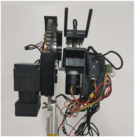
Figure 1.
Prototype of the cable-stripping robot.
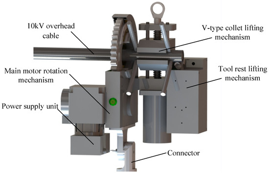
Figure 2.
Structure of the cable-stripping robot.
The key parameters of the cable-stripping robot in stable operation are shown in Table 1.

Table 1.
Key parameters of the cable-stripping robot.
Figure 3 depicts the full robotic system, which consists of a cable-stripping robot, a wireless remote handle, and an insulating rod. The system’s operational steps are as follows. First install the wire-stripping robot adapter at the end of the insulating rod. Next, make your way to the area near the overhead line. Radio frequency modules are used to connect the robot and the supplemental remote handle. The robot is given commands via the auxiliary remote-control device, which also directs it to carry out the necessary actions. The robot’s real-time data are sent to the supplementary remote handle through the wireless modules.
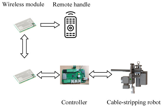
Figure 3.
The entire cable-stripping robotic system.
3. A Cascade BPNN–PID Controller for the Cable-Stripping Robot
3.1. General Scheme of the Robot Controller
In this design, the controller manages each motor speed separately to achieve precise control of each robot mechanism and accomplish the wire-stripping task. The PID approach, regulated by the BP neural network, is used to implement motor control. Figure 4 depicts the cable-stripping robot’s overall control architecture.
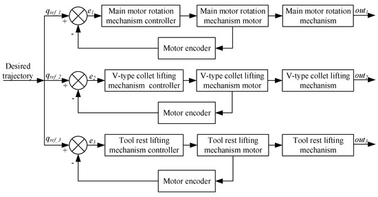
Figure 4.
Motion control scheme of the cable- stripping robot.
3.2. BP Neural Network
A three-layer BP neural network comprising a input neurons b hidden neurons and c output neurons is depicted in Figure 5 [14]. The threshold of the ith neuron in the hidden layer is δi and the weight from the input layer to the hidden layer is wij. The threshold of the hth neuron in the output layer is set to θh, and the weight from the hidden layer to the output layer is set to whi.
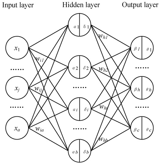
Figure 5.
BP neural network with three layers.
The input of the ith neuron in the hidden layer can be obtained via the weighted sum of signals in the input layer.
The input matrix in the hidden layer is expressed as
The input of the output layer can be obtained as follows.
where mi is activation functions in the hidden layer.
Activation functions in the output layer are as follows.
Define output error function as
where yh is the actual output value, and yh* is the expected output value.
In summary, whi first affects βh, then affects yh, and finally affects Ek [15]. Therefore, the weight correction Δwhi(n) is
The derivative of the activation function can be obtained
The weight increment from the hidden layer to the output layer is
where η is the learning efficiency.
The weight whi(n + 1) from the hidden layer to the output layer after adjustment is
The correction value Δθh(n) of the threshold from the hidden layer to the output layer is
After adjustment, the threshold value θh(n + 1) from the hidden layer to the output layer is
Similarly, the weight correction Δwij(n) and threshold correction δi(n) from the input layer to the hidden layer can be written as follows.
wij(n + 1), the weight from the input layer to the hidden layer after adjustment, is
The adjusted threshold δi(n + 1) from the input layer to the hidden layer is
Weight and threshold corrections are iterated until the end of the iteration.
3.3. Cascade PID Controller Tuned via BP Neural Network
According to tracking errors, the BP neural network modifies the PID parameters [16,17,18]. Figure 6 depicts the BP neural network’s cascade PID control principle.
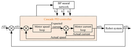
Figure 6.
Cascade BPNN–PID controller.
The weight whi from the input layer to the hidden layer, the weight wij from the hidden layer to the output layer, and the learning efficiency η must all be determined in order to adjust the cascade PID controller using BPNN. The neural network layout in Figure 6 is condensed to nine input neurons and four output neurons in order to enhance the algorithm’s convergence. The layers that make up the input are e(k), e(k − 1), e(k − 2), y(k), y(k − 1), r(k), u(k − 1), the hidden layer and output layer weight coefficient (k − 2), and the hidden layer and output layer weight coefficient (k − 1); the layers that make up the output are u(k), kp, ki and kd [19].
The following describes how the BPNN tuned cascade PID control strategy iterates.
- (1)
- BPNN calculates inputs and outputs of each layer, and finally takes the output neuron of the output layer as the parameters kp, ki, and kd of the PID algorithm;
- (2)
- The controller outputs u(k) through PID calculation, and finally the robot outputs y(k);
- (3)
- Calculate the weight whi(k + 1) from the input layer to the hidden layer and the weight wij(k + 1) from the hidden layer to the output layer;
- (4)
- Calculate output quantities kp, ki, and kd in the output layer;
- (5)
- Calculate the output control quantity u(k) of BPNN through the PID cascade controller;
- (6)
- Set k = k + 1 and return to step (2).
4. Experiments and Analysis
After designing the mechanical system and control system of the cable-stripping robot, the experimental setup of the cable-stripping robot is built, as shown in Figure 7. The 95 mm2 cross-sectional area wire utilized in these experiments is frequently used in distribution networks. In Figure 8, the experimental procedure is displayed.
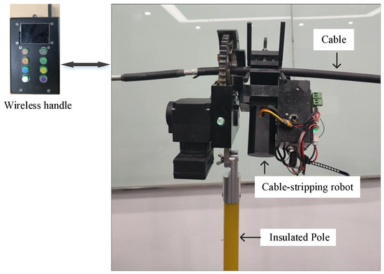
Figure 7.
Experimental setup of the cable-stripping robot.
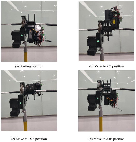
Figure 8.
Stripping process of the robot.
Figure 9 depicts how the stripped cable skin appeared using different controllers. Evidently, the robot’s cascade BPNN–PID controller provided superior stripping performance compared with the traditional cascade PID algorithm; Figure 9b shows less cable skin damage as a result.
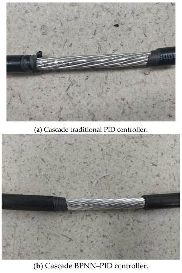
Figure 9.
Stripped appearance using different controllers.
The experimental test of the robot sampled the motor speed of each mechanism. The expected speed of the rotating mechanism of the main motor was set at 28.6 rpm. Figure 10 shows the response curve of the cascaded traditional PID algorithm and the cascaded BPNN–PID method. It can be seen from the figure that the speed response curve range of the cascade PID output was [15, 40] rpm, and the maximum error floating rate was 47.5%; in contrast, the speed response curve range of the cascade BPNN–PID output was [23, 33] rpm, and the maximum error floating rate was 19.5%. This further proves the superior performance and strong robustness of the BPNN adjustment algorithm.
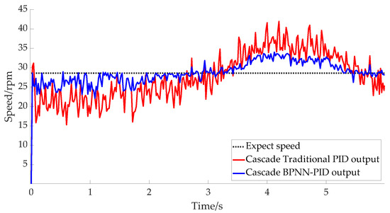
Figure 10.
Responses of main motor rotating mechanisms.
The V-type collet was expanded and the cable was clamped after adjusting the motor speed of the V-type collet lifting mechanism to 28.6 rpm. The speed response curves for the motor using the two controllers are shown in Figure 11, where it can be seen that the output response curve range of the BPNN–PID controller was [25, 30] rpm, and the maximum error floating rate was 12.5%, whereas the output range of the traditional PID response curve was [22, 34] rpm, and the maximum error floating rate was 23.1%. This also indicates that although the robot’s response using the BPNN–PID controller was better than that using the traditional PID controller, this advantage was not obvious. This is because in general, the actual speed output under the two controllers often fluctuated during the big gear rotation. When the tool rest and V-chuck lifting mechanism increased with the rotation of the gear, the speed was slightly slower. The gravitational effect made the velocity increase after the peak period until it finally reached the ideal level, while the external disturbance was relatively small.
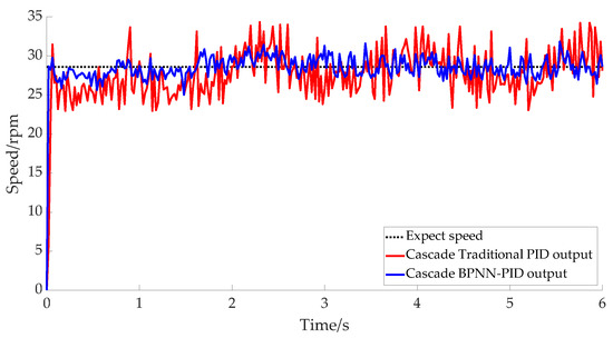
Figure 11.
V-type collet-lifting mechanism actual speed outputs.
The motor speed of the tool rest lifting mechanism was set at 5.7 rpm. The speed response over time in Figure 12 shows that the overall process of the tool rest lifting was relatively stable. The output speed range of the cascade BPNN–PID method was [5.1, 6.2] rpm, and the maximum error floating rate was 10.5%, whereas that of cascade PID method was [4.9, 6.9] rpm. The maximum error fluctuation rate was 21.1%, which further indicates that the cascade BPNN–PID method is superior to the cascade PID method in terms of fluctuation and velocity response. The cascade BPNN–PID controller was more efficient than the traditional cascade PID controller.
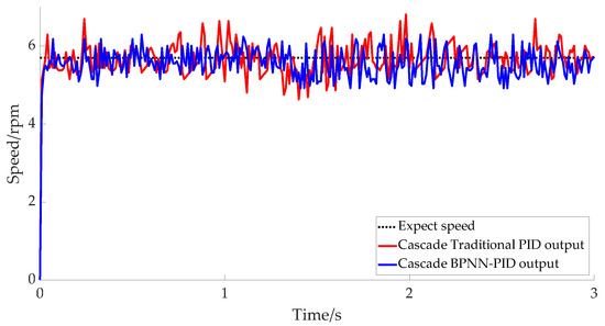
Figure 12.
Tool rest lifting mechanism actual speed outputs.
We performed 25 cable-stripping tests using the cascade BPNN–PID algorithm, measuring the length of peeled wire, the time it took to strip the cable, and the degree of cable damage. Table 2 displays the results of the wire-stripping test. The findings of 25 group tests reveal the stripping times of five group lengths (5 cm, 10 cm, 15 cm, 20 cm, and 25 cm) with an average stripping speed of 6.25 cm/min. The system’s stability could be preserved as a result of the moderate stripping pace. At the same time, analysis of the damage situation indicated that the wire stripper would also be slightly damaged. This was because the high voltage cable was excessively bent during installation, resulting in a delay in tool adjustment; this needs to be improved in the future. However, analysis of the task completion rate indicated that the integrity rate reached higher than 70%, further attesting to the robot’s high reliability; in addition, the cable damage effect showed that the damage was tolerable.

Table 2.
Test data for wire-stripping experiments.
5. Conclusions
In this paper, a cable-stripping robot for distribution lines was designed; the robot is light in weight, small in size, and easy to carry, which is helpful for power workers who perform outdoor work. To improve the working stability of the cable-stripping robot, its cascade BPNN–PID control scheme was investigated, and experiments were carried out to assess its performance. The cable-stripping robot’s tests were used to assess the mechanical structure’s logic, the system’s hardware and software, and the adaptive control algorithm’s dependability. The cable-stripping robot helped increase live working efficiency and advanced smart grid development.
Author Contributions
Conceptualization, J.Z. and Z.H.; mechanism, Z.W.; software, S.H. All authors have read and agreed to the published version of the manuscript.
Funding
This research was funded by the National Natural Science Foundation of China, grant number 52275285; and the Science and Technology planning projects of Changzhou, grant number CE20215052.
Data Availability Statement
Data presented in this study are available on request from the corresponding author.
Conflicts of Interest
The authors declare no conflict of interest.
References
- Menendez, O.; Auat Cheein, F.A.; Perez, M.; Kouro, S. Robotics in power systems: Enabling a more reliable and safe grid. IEEE Ind. Electron. Mag. 2017, 11, 22–34. [Google Scholar] [CrossRef]
- Katrasnik, J.; Pernus Franjo Likar, B. A survey of mobile robots for distribution power line inspection. IEEE Trans. Power Deliv. 2010, 25, 485–493. [Google Scholar] [CrossRef]
- Takaoka, K.; Yokoyama, K.; Wakisako, H.; Yano, K.; Higashijima, K.; Murakami, S. Development of the fully-automatic live-line maintenance robot-Phase III. In Proceedings of the 2001 IEEE International Symposium on Assembly and Task Planning (ISATP2001), Assembly and Disassembly in the Twenty-First Century (Cat. No. 01TH8560), Fukuoka, Japan, 29 May 2001; IEEE: Piscataway, NJ, USA, 2001; pp. 423–428. [Google Scholar]
- Park, J.Y.; Cho, B.H.; Byun, S.H.; Lee, J.K. Development of cleaning robot system for live-line suspension insulator strings. Int. J. Control Autom. Syst. 2009, 7, 211–220. [Google Scholar] [CrossRef]
- Sawada, J.; Kusumoto, K.; Maikawa, Y.; Munakata, T.; Ishikawa, Y. A mobile robot for inspection of power transmission lines. IEEE Trans. Power Deliv. 1991, 6, 309–315. [Google Scholar] [CrossRef]
- Nakashima, M.; Yano, K.; Maruyama, Y.; Yakabe, H. The hot line work robot system “Phase II” and its human-robot interface “MOS”. In Proceedings of the 1995 IEEE/RSJ International Conference on Intelligent Robots and Systems, Human Robot Interaction and Cooperative Robots, Pittsburgh, PA, USA, 5–9 August 1995; IEEE: Piscataway, NJ, USA, 1995; Volume 2, pp. 116–123. [Google Scholar]
- Gonçalves, R.S.; Carvalho, J. A mobile robot to be applied in high-voltage power lines. J. Braz. Soc. Mech. Sci. Eng. 2014, 37, 349–359. [Google Scholar] [CrossRef]
- Tang, M.; Gu, Y.; Wang, S.; Liang, Q. DCBot: An autonomous hot-line working robot for 110 kV substation. Robot. Auton. Syst. 2019, 119, 247–262. [Google Scholar] [CrossRef]
- Zhang, Y.; Wang, T.; Li, J.; Yao, Y.; Zhou, X. Research on new type of live working robot system for overhead transmission lines. J. Phys. Conf. Ser. 2018, 1074, 012040. [Google Scholar] [CrossRef]
- Yano, K.; Maruyama, Y.; Morita, K.; Nakashima, M. Development of the semi-automatic hot-line work robot system “Phase II”. In Proceedings of the ESMO’95—1995 IEEE 7th International Conference on Transmission and Distribution Construction, Operation and Live-Line Maintenance, Columbus, OH, USA, 29 October–3 November 1995; IEEE: Piscataway, NJ, USA, 1995; pp. 212–218. [Google Scholar]
- Yan, Y.; Jiang, W.; Zou, D.; Quan, W.; Li, H.J.; Lei, Y.; Zhou, Z.F. Research on mechanism configuration and coordinated control for power distribution network live working robot. Ind. Robot. 2020, 47, 453–462. [Google Scholar] [CrossRef]
- Yu, Y.; Zhou, Z.; Liu, W.; Hu, S.; Xu, X. The Design and Simulation Analysis of Distribution Network Stripper Structure. J. Phys. Conf. Ser. 2020, 1486, 062035. [Google Scholar] [CrossRef]
- Zhang, L.; He, Y.; Xu, S.; Zhang, T.; Guo, J.; Wang, M. Mechanical design and finite element analysis of live working robot for 10kV distribution power systems. Procedia Comput. Sci. 2021, 183, 331–336. [Google Scholar] [CrossRef]
- Guo, C.; Song, Q.; Cai, W. A Neural Network Assisted Cascade Control System for Air Handling Unit. IEEE Trans. Ind. Electron. 2007, 54, 620–628. [Google Scholar] [CrossRef]
- Wu, X.; Chen, H.; Wang, Y.; Shu, L.; Liu, G. BP neural network based continuous objects distribution detection in WSNs. Wirel. Netw. 2016, 22, 1917–1929. [Google Scholar] [CrossRef]
- Auer, P.; Burgsteiner, H.; Maass, W. A learning rule for very simple universal approximators consisting of a single layer of perceptrons. Neural Netw. 2008, 21, 786–795. [Google Scholar] [CrossRef] [PubMed]
- Wang, W.; Tang, R.; Li, C.; Liu, P.; Luo, L. A BP neural network model optimized by Mind Evolutionary Algorithm for predicting the ocean wave heights. Ocean. Eng. 2018, 162, 98–107. [Google Scholar] [CrossRef]
- Zhou, Y.; Zhang, Y.; Yang, T. Research on load simulator control strategy based on BP neural network and PID method. MATEC Web Conf. 2020, 306, 03002. [Google Scholar] [CrossRef]
- Chen, M.R.; Chen, B.P.; Zeng, G.Q.; Lu, K.D.; Chu, P. An adaptive fractional-order BP neural network based on extremal optimization for handwritten digits recognition. Neurocomputing 2020, 391, 260–272. [Google Scholar] [CrossRef]
Disclaimer/Publisher’s Note: The statements, opinions and data contained in all publications are solely those of the individual author(s) and contributor(s) and not of MDPI and/or the editor(s). MDPI and/or the editor(s) disclaim responsibility for any injury to people or property resulting from any ideas, methods, instructions or products referred to in the content. |
© 2023 by the authors. Licensee MDPI, Basel, Switzerland. This article is an open access article distributed under the terms and conditions of the Creative Commons Attribution (CC BY) license (https://creativecommons.org/licenses/by/4.0/).