
MEMS Fluxgate Sensor Based on Liquid Casting

 ,
, 

Abstract
:1. Introduction
2. Design and Simulation
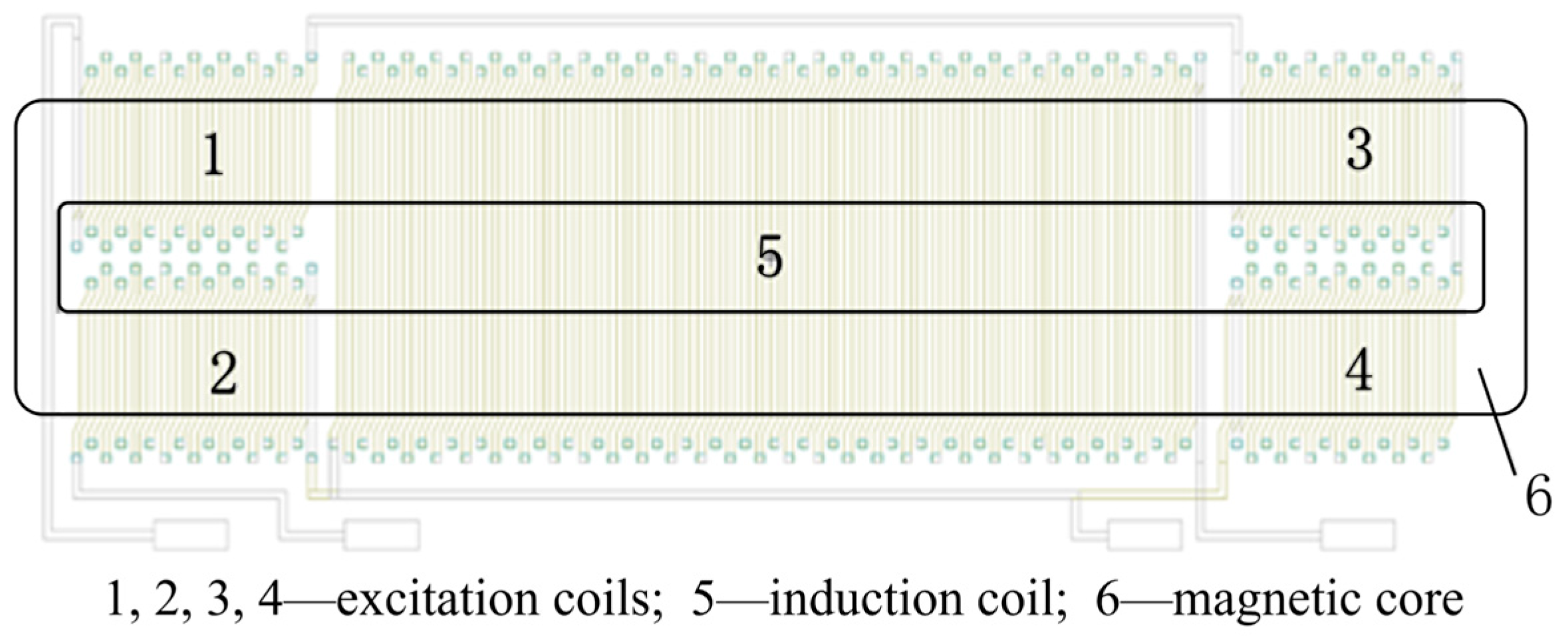
2.1. The Design of MEMS Fluxgate
2.2. Finite Element Analysis
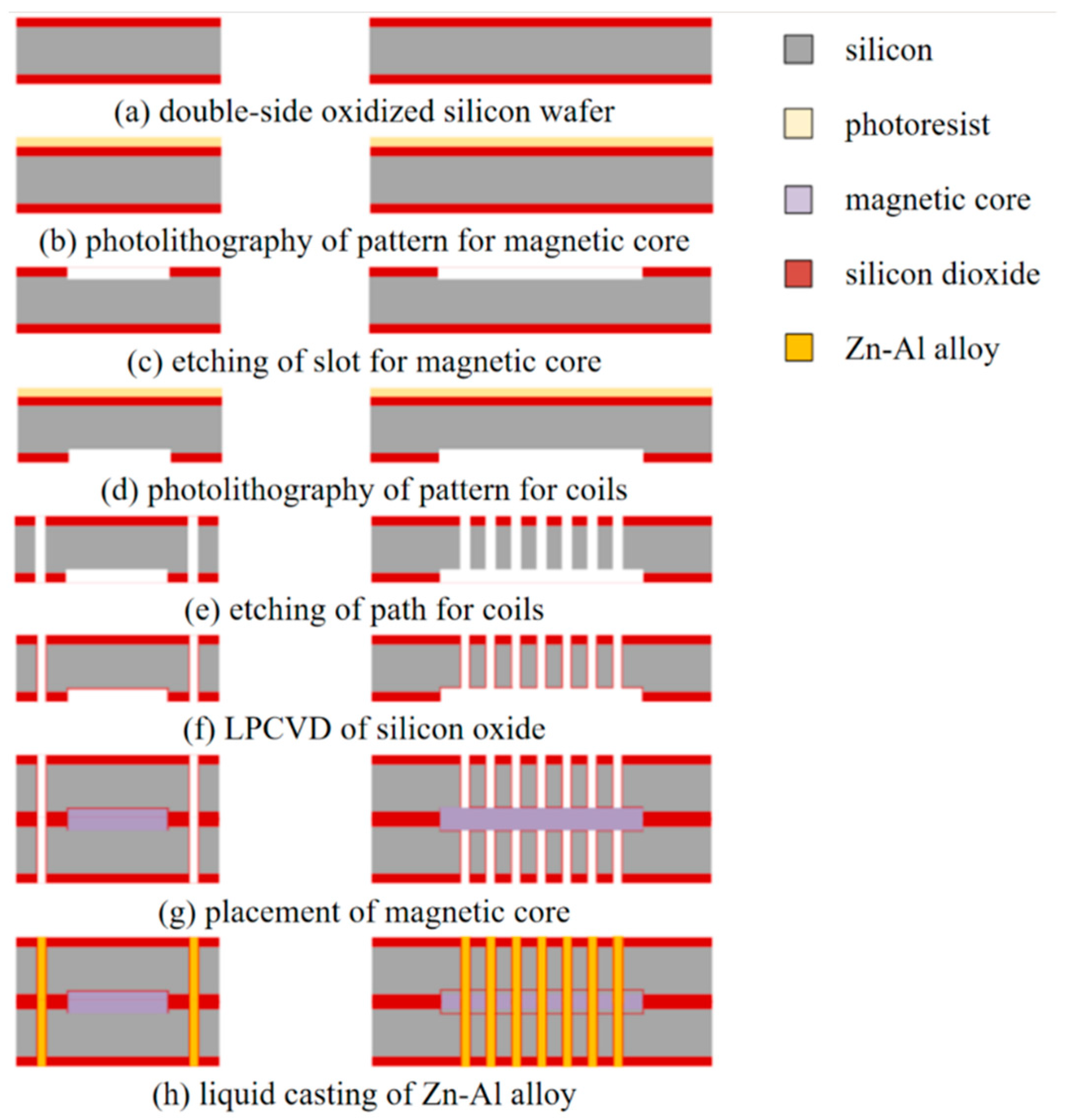
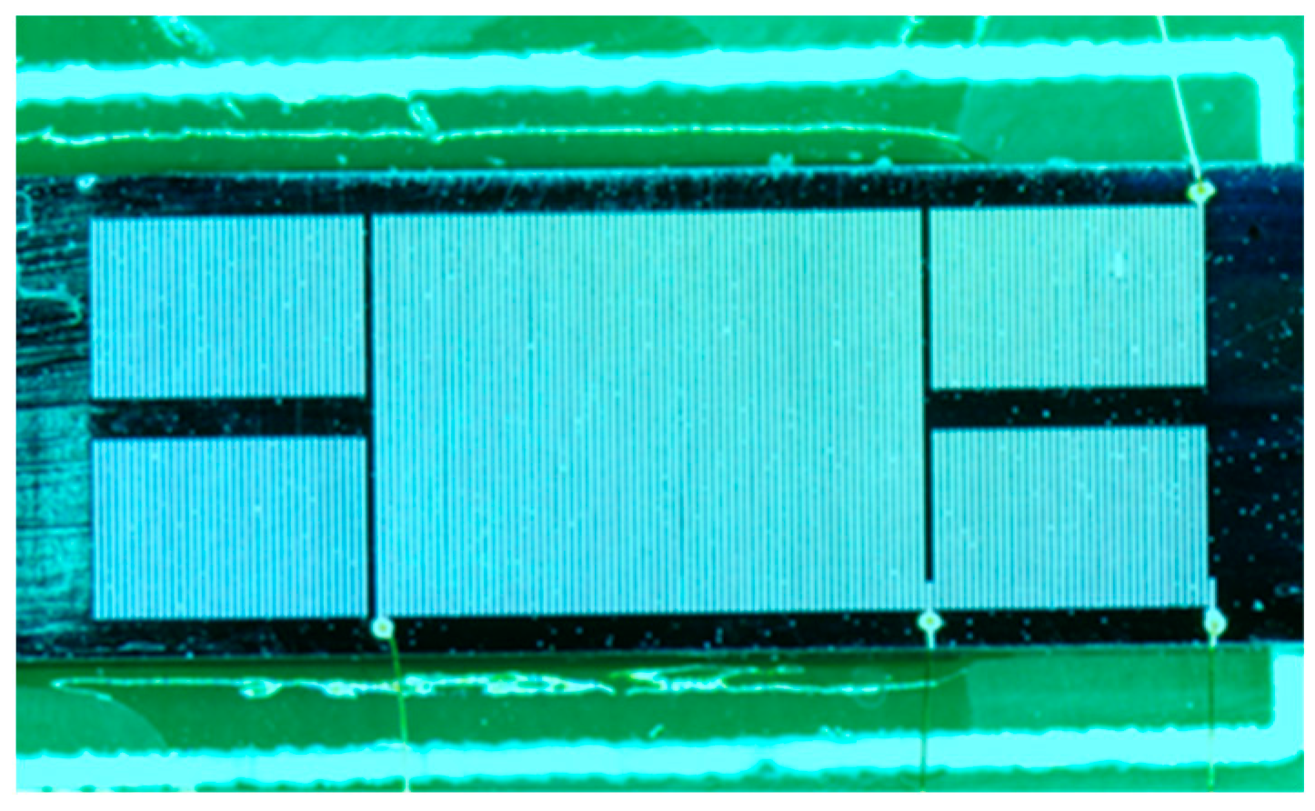
3. Fabrication
4. Device Testing
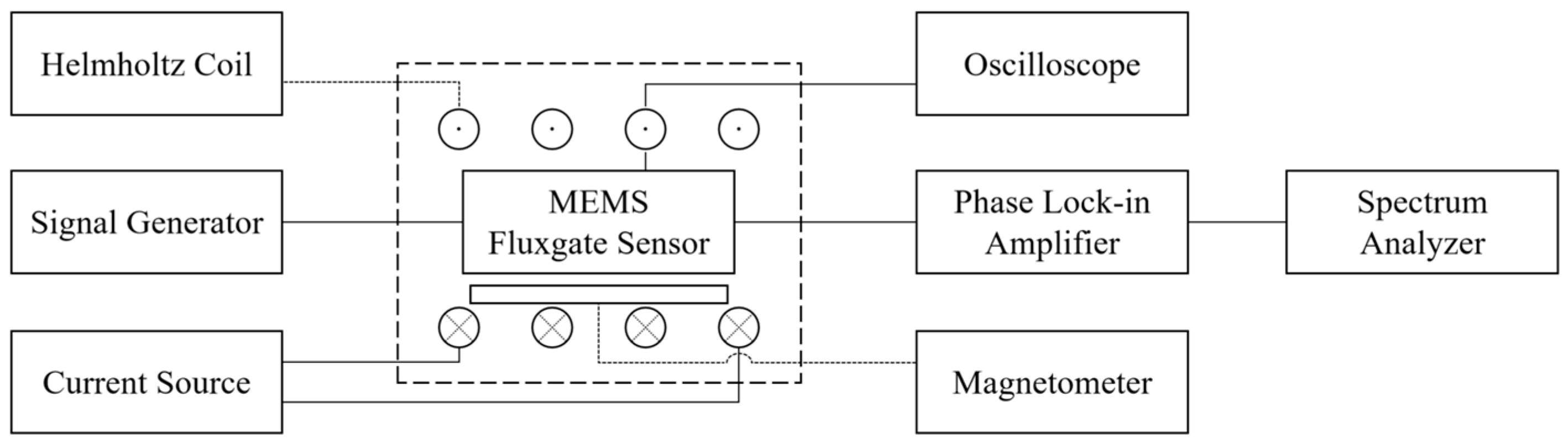
4.1. Testing System
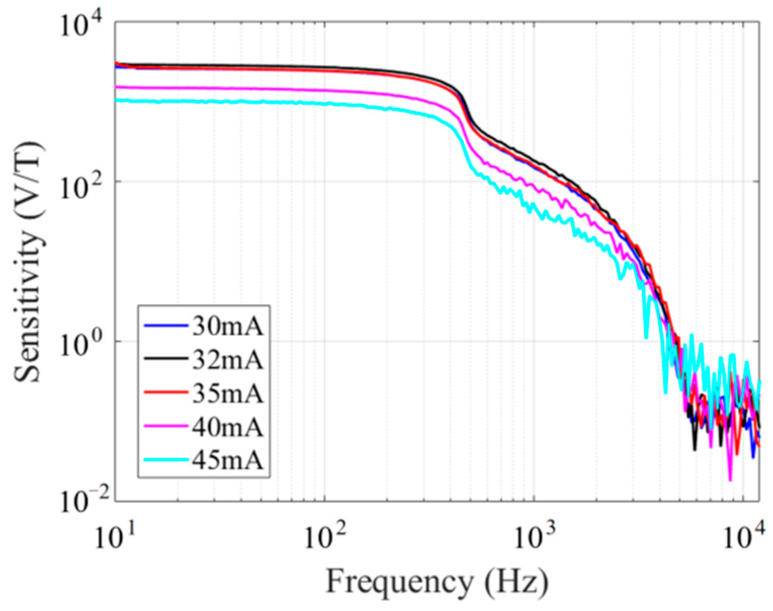
4.2. Results
4.3. Discussion
5. Conclusions
Author Contributions
Funding
Data Availability Statement
Conflicts of Interest
References
- Kirchhoff, M.R.; Büttgenbach, S. MEMS fluxgate magnetometer for parallel robot application. Microsyst. Technol. 2010, 16, 787–790. [Google Scholar] [CrossRef]
- Russell, C.T.; Anderson, B.J.; Baumjohann, W.; Bromund, K.R.; Dearborn, D.; Fischer, D.; Le, G.; Leinweber, H.K.; Leneman, D.; Magnes, W.; et al. The magnetospheric multiscale magnetometers. Space Sci. Rev. 2016, 199, 189–256. [Google Scholar] [CrossRef]
- Janosek, M.; Butta, M.; Dressler, M.; Saunderson, E.; Novotny, D.; Fourie, C. 1-pT noise fluxgate magnetometer for geomagnetic measurements and unshielded magnetocardiography. IEEE Trans. Instrum. Meas. 2020, 69, 2552–2560. [Google Scholar] [CrossRef]
- Snoeij, M.F.; Schaffer, V.; Udayashankar, S.; Ivanov, M.V. Integrated fluxgate magnetometer for use in isolated current sensing. IEEE J. Solid-State Circuits 2016, 51, 1684–1694. [Google Scholar] [CrossRef]
- Chiesi, L.; Kejik, P.; Janossy, B.; Popovic, R.S. CMOS planar 2D micro-fluxgate sensor. Sens. Actuators A-Phys. 2000, 82, 174–180. [Google Scholar] [CrossRef]
- Drljaca, P.M.; Vincent, F.; Kejik, P.; Popovic, R.S. Advanced process of the magnetic core integration for the micro fluxgate magnetometer. Sens. Actuators A-Phys. 2006, 129, 58–61. [Google Scholar] [CrossRef]
- Baschirotto, A.; Dallago, E.; Malcovati, P.; Marchesi, M.; Melissano, E.; Morelli, M.; Siciliano, P.; Venchi, G. An integrated micro-fluxgate magnetic sensor with front-end circuitry. IEEE Trans. Instrum. Meas. 2009, 58, 3269–3275. [Google Scholar] [CrossRef]
- Lu, C.C.; Liu, Y.T.; Jhao, F.Y.; Jeng, J.-T. Responsivity and noise of a wire-bonded CMOS micro-fluxgate sensor. Sens. Actuators A-Phys. 2012, 179, 39–43. [Google Scholar] [CrossRef]
- Yoon, J.B.; Han, C.H.; Yoon, E.; Kim, C.K. Novel and high-yield fabrication of electroplated 3D micro-coils for MEMS and microelectronics. In Proceedings of the SPIE Conference on Micromachining and Microfabrication Process Technology IV, Santa Clara, CA, USA, 31 August 1998. [Google Scholar]
- Lei, C.; Wang, R.; Zhou, Y.; Zhou, Z. MEMS micro fluxgate sensors with mutual vertical excitation coils and detection coils. Microsyst. Technol. 2009, 15, 969–972. [Google Scholar] [CrossRef]
- Lei, C.; Liu, Y.; Sun, X.C.; Wang, T.; Yang, Z.; Zhou, Y. Improved performance of integrated solenoid fluxgate sensor chip using a bilayer Co-based ribbon core. IEEE Sens. J. 2015, 15, 5010–5014. [Google Scholar] [CrossRef]
- Zhi, S.T.; Feng, Z.; Guo, L.; Lei, C.; Zhou, Y. Investigation of a novel MEMS orthogonal fluxgate sensor fabricated with Co-based amorphous ribbon core. Sens. Actuators A-Phys. 2017, 267, 121–126. [Google Scholar] [CrossRef]
- Gu, J.; Hou, X.; Xia, X.; Li, X. Solenoid fluxgate current sensor micromachined by wafer-level melt-metal casting technique, In Proceedings of 2019 IEEE 32nd International Conference on Micro Electro Mechanical Systems (MEMS). Seoul, Republic of Korea, 27–31 January 2019. [Google Scholar]
- Gu, J.; Hou, X.; Xia, X.; Zhang, W.; Li, X. MEMS fluxgate magnetometer whose solenoid coil are winded by a novel wafer-level liquid alloy filling method. In Proceedings of the 2nd Electron Devices Technology and Manufacturing Conference, Kobe, Japan, 13–16 March 2018. [Google Scholar]
- Marconato, N. Design of Integrated Micro-Fluxgate Magnetic Sensors: Advantages and Challenges of Numerical Analyses. Sensors 2022, 22, 961. [Google Scholar] [CrossRef]
- Elkattan, M.; Mostafa, H.; Khalil, A.H. Effect of Excitation Parameters on Fluxgate Sensing Element Response, In Proceedings of 2021 IEEE Regional Symposium on Micro and Nanoelectronics (RSM). Kuala Lumpur, Malaysia, 2–4 August 2021. [Google Scholar]
- Janosek, M. Parallel fluxgate magnetometers. In High Sensitivity Magnetometers; Grosz, A., Haji-Sheikh, M., Mukhopadhyay, S., Eds.; Springer: Cham, Switzerland, 2017; pp. 41–61. [Google Scholar]
- Amorphous Ribbons and Components. Available online: https://www.antai-emarketing.com/amorphous-ribbons-and-components (accessed on 1 November 2023).
- Nosenko, A.V.; Kyrylchuk, V.V.; Semen’ko, M.P.; Nowicki, M.; Marusenkov, A.; Mika, T.M.; Semyrga, O.M.; Zelinska, G.M.; Nosenko, V.K. Soft magnetic cobalt based amorphous alloys with low saturation induction. J. Magn. Magn. Mater. 2020, 515, 167328. [Google Scholar] [CrossRef]
- Xu, M.; Quan, M.X.; Hu, Z.Q.; Cheng, L.Z.; He, K.Y. Thermal stability and magnetic properties of amorphous Fe-based alloys with significant supercooled liquid region. J. Alloys Compd. 2002, 334, 238–242. [Google Scholar] [CrossRef]
- Stoica, M.; Kumar, S.; Roth, S.; Ram, S.; Eckert, J.; Vaughan, G.; Yavari, A.R. Crystallization kinetics and magnetic properties of Fe66Nb4B30 bulk metallic glass. J. Alloys Compd. 2009, 483, 632–637. [Google Scholar] [CrossRef]
- Guo, L.; Wang, C.; Zhi, S.; Feng, Z.; Lei, C.; Zhou, Y. Wide linearity range and highly sensitive MEMS-based micro-fluxgate sensor with double-layer magnetic core made of Fe–Co–B amorphous alloy. Micromachines 2017, 8, 352. [Google Scholar] [CrossRef] [PubMed]
- Lei, J.; Lei, C.; Zhou, Y. Micro fluxgate sensor using solenoid coils fabricated by MEMS technology. Meas. Sci. Rev. 2012, 12, 286–289. [Google Scholar] [CrossRef]


| Parameter | This Work | [22] | [23] | [11] | [12] |
|---|---|---|---|---|---|
| Fabrication of coils | Liquid casting | Electroplating | Electroplating | Electroplating | Electroplating |
| Sensitivity | 2847 V/T | 1945 V/T | 583.1 V/T | 3165 V/T | 575 V/T |
| Noise@1 Hz | 306 pT/rtHz | 36 pT/rtHz | 13.57 nT/rtHz | 500 pT/rtHz | 200 pT/rtHz |
| Power | 43.9 mW | — | 33.75 mW | 183 mV | — |
| Excitation current | 32 mA | 70 mA | 150 mA | 240 mA | 90 mA |
| Size of sensors | 5 × 12 mm2 | 2.7 × 7.3 mm2 | 5.5 × 5.8 mm2 | 6.74 × 9 mm2 | 6.4 × 9.4 mm2 |
Disclaimer/Publisher’s Note: The statements, opinions and data contained in all publications are solely those of the individual author(s) and contributor(s) and not of MDPI and/or the editor(s). MDPI and/or the editor(s) disclaim responsibility for any injury to people or property resulting from any ideas, methods, instructions or products referred to in the content. |
© 2023 by the authors. Licensee MDPI, Basel, Switzerland. This article is an open access article distributed under the terms and conditions of the Creative Commons Attribution (CC BY) license (https://creativecommons.org/licenses/by/4.0/).
Share and Cite
Yang, Y.; Xu, W.; Chen, G.; Jin, Z.; Wang, D.; Mai, Z.; Xing, G.; Chen, J. MEMS Fluxgate Sensor Based on Liquid Casting. Micromachines 2023, 14, 2159. https://doi.org/10.3390/mi14122159
Yang Y, Xu W, Chen G, Jin Z, Wang D, Mai Z, Xing G, Chen J. MEMS Fluxgate Sensor Based on Liquid Casting. Micromachines. 2023; 14(12):2159. https://doi.org/10.3390/mi14122159
Chicago/Turabian StyleYang, Ying, Wei Xu, Guangyuan Chen, Zhenhu Jin, Dandan Wang, Zhihong Mai, Guozhong Xing, and Jiamin Chen. 2023. "MEMS Fluxgate Sensor Based on Liquid Casting" Micromachines 14, no. 12: 2159. https://doi.org/10.3390/mi14122159
APA StyleYang, Y., Xu, W., Chen, G., Jin, Z., Wang, D., Mai, Z., Xing, G., & Chen, J. (2023). MEMS Fluxgate Sensor Based on Liquid Casting. Micromachines, 14(12), 2159. https://doi.org/10.3390/mi14122159