


Study on the Influence of Coil Arrangement on the Output Characteristics of Electromagnetic Galloping Energy Harvester


Abstract
:1. Introduction
2. Modeling, Analysis, and Experimental Setup
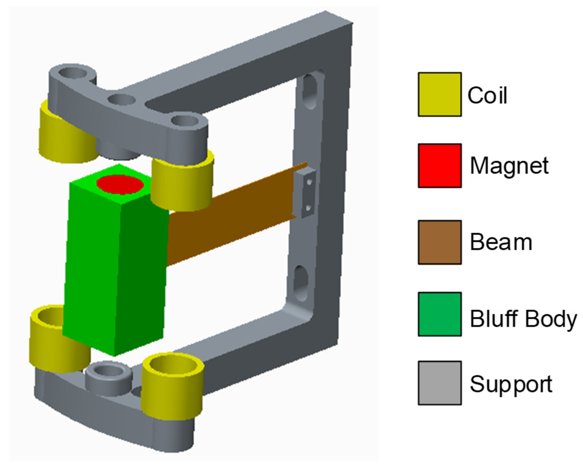
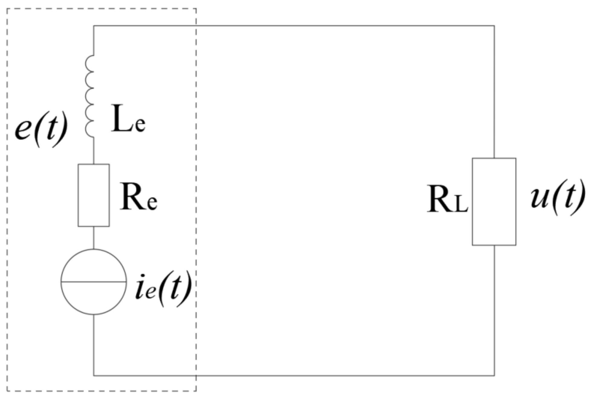
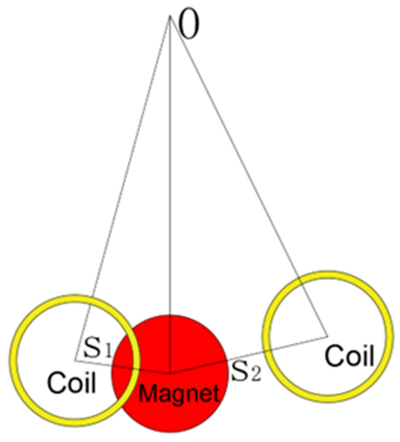
2.1. Modeling
2.2. Analysis
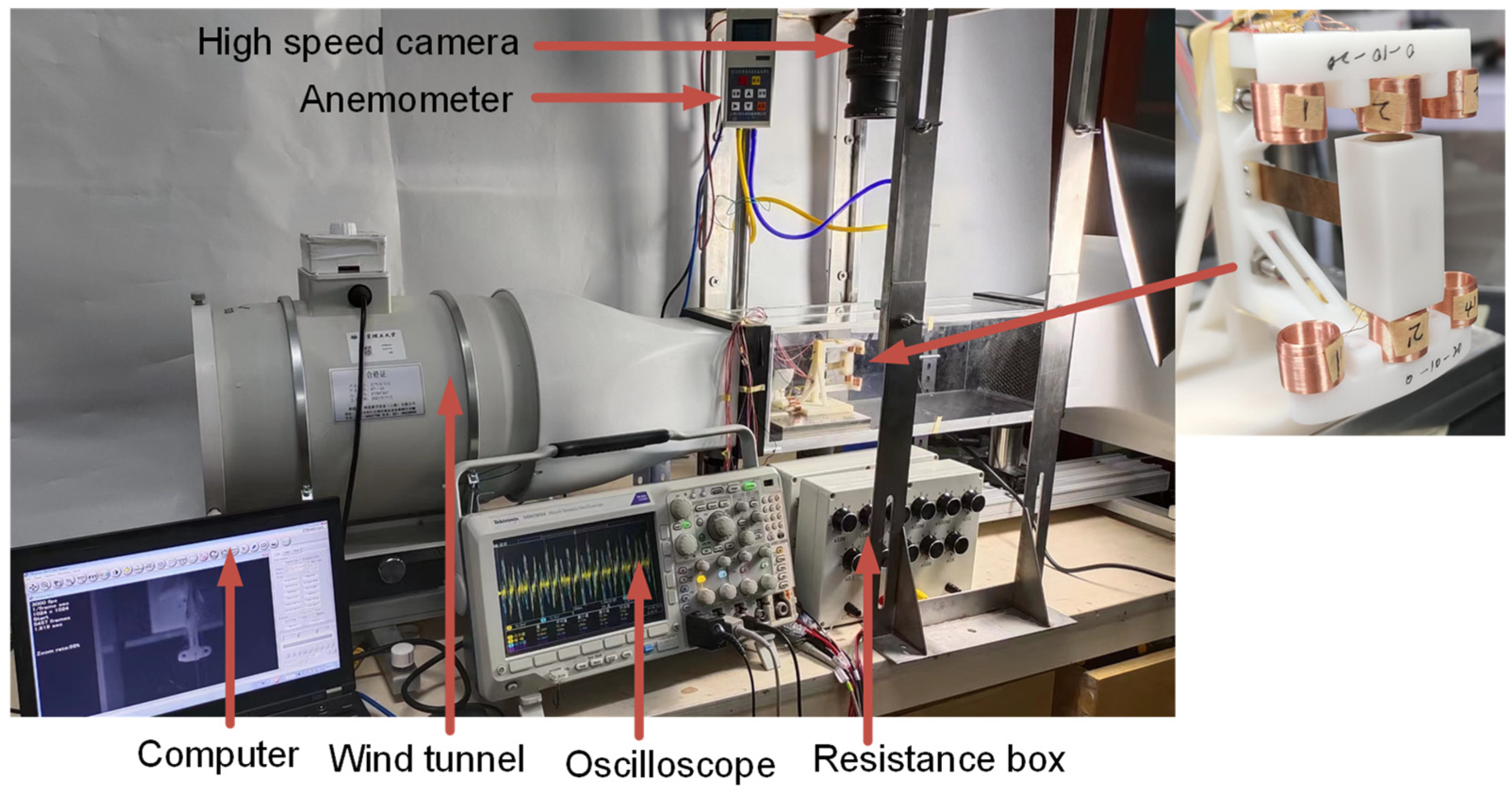
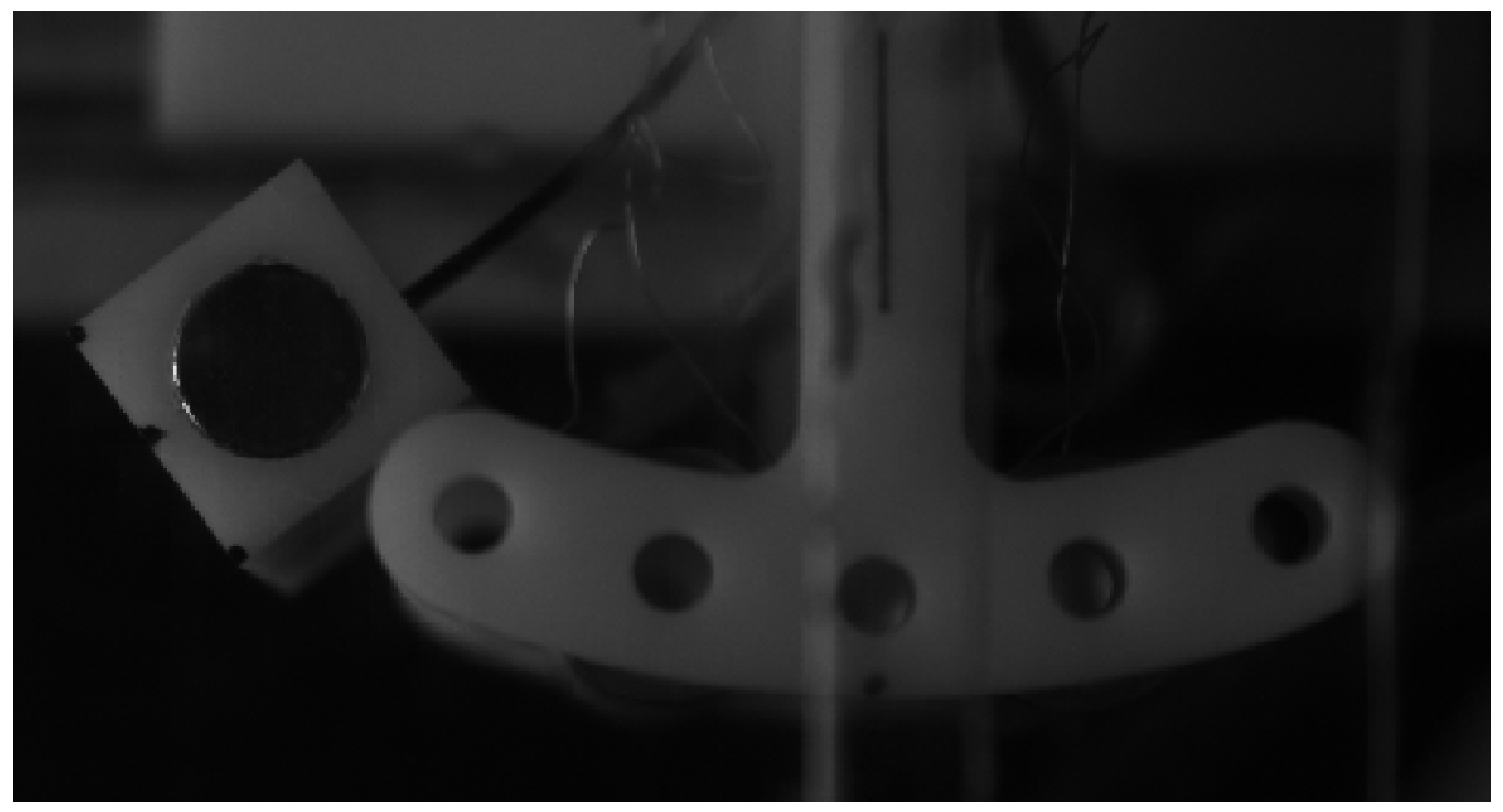
2.3. Experimental Setup and Parameter Identifications
3. Experiment and Discussion
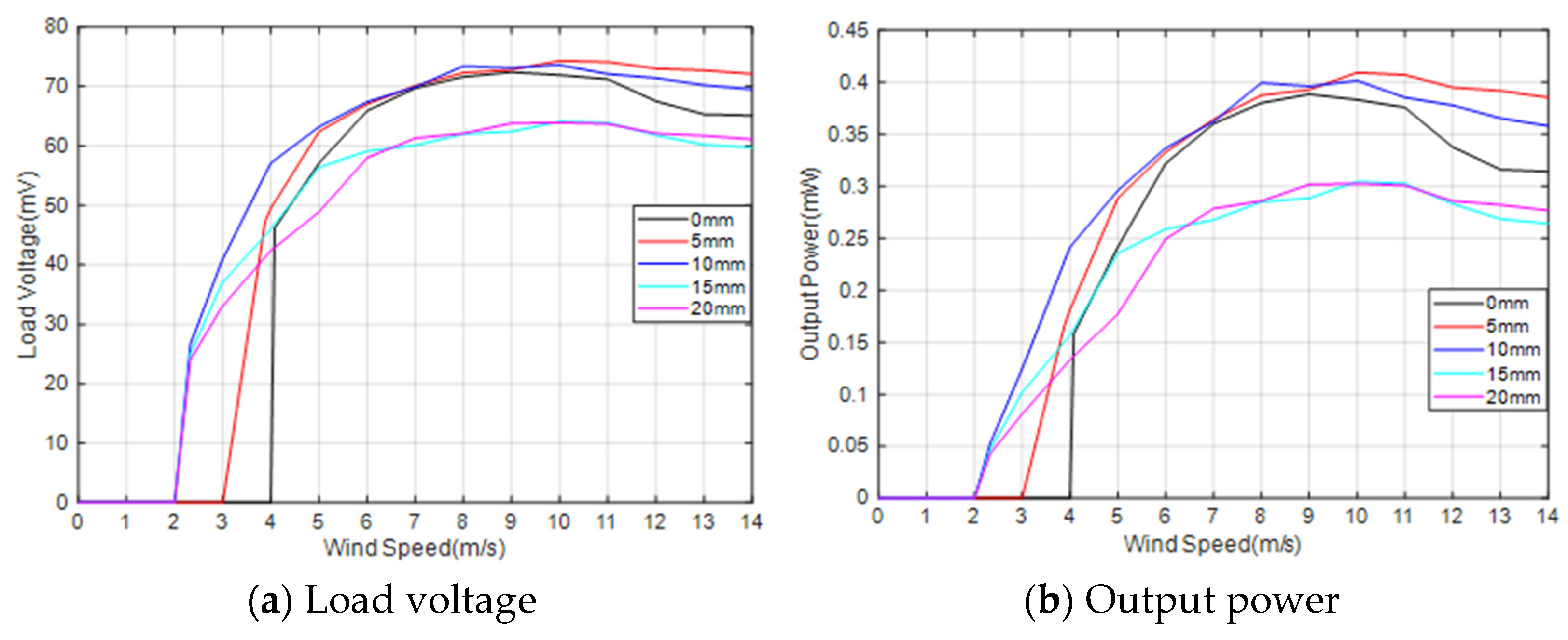
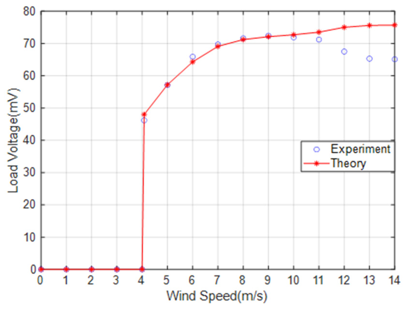
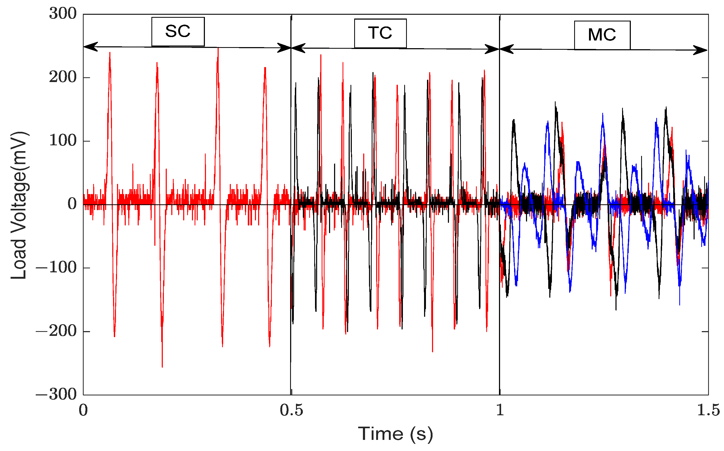
3.1. Output Response of the MEGEH
3.1.1. The Output Response of the SC
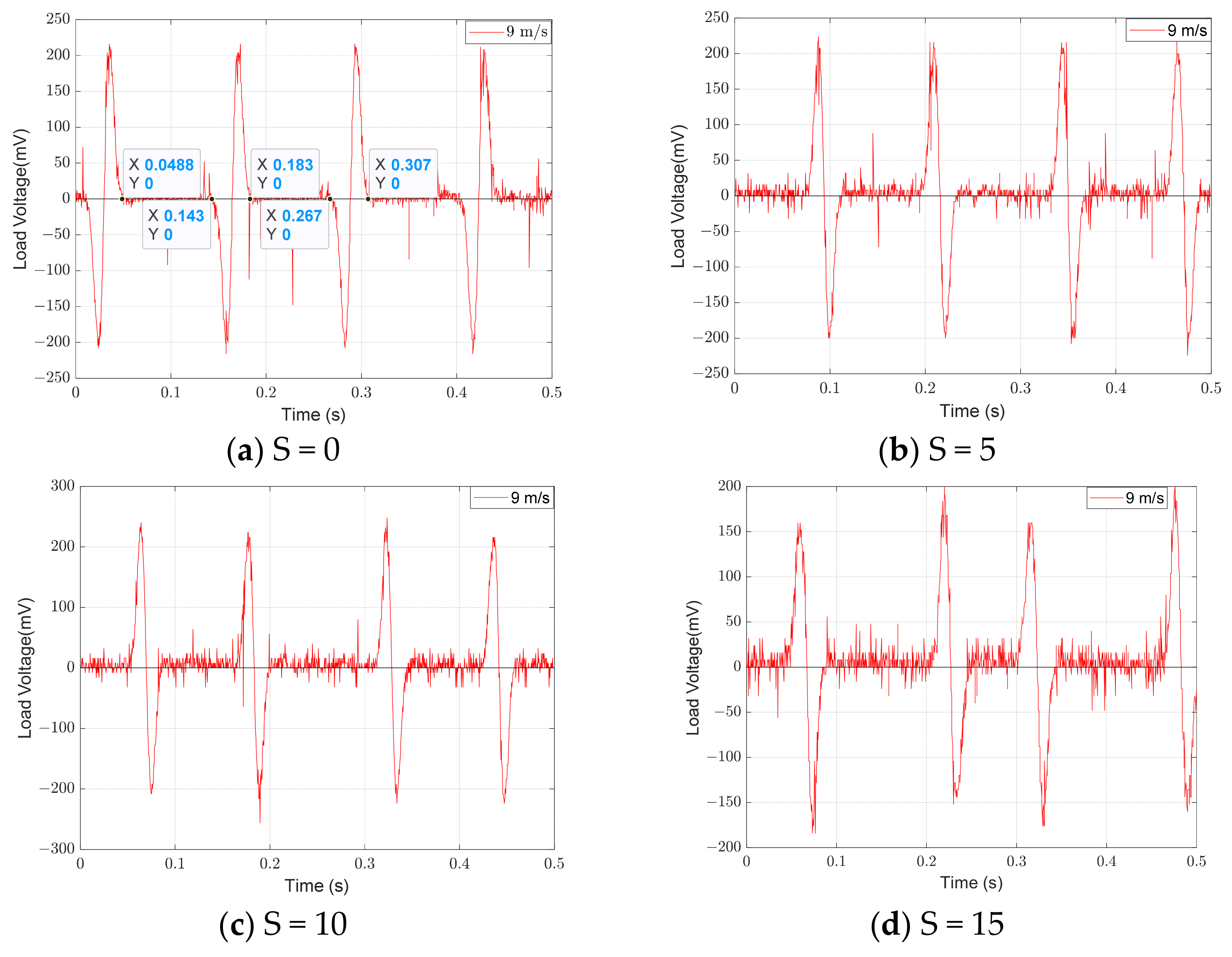
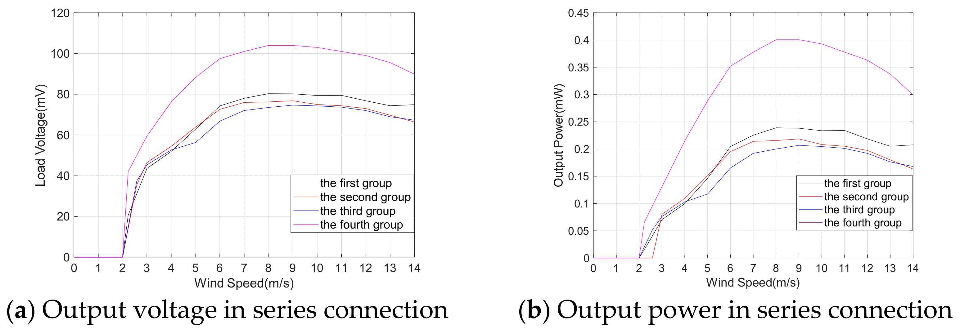
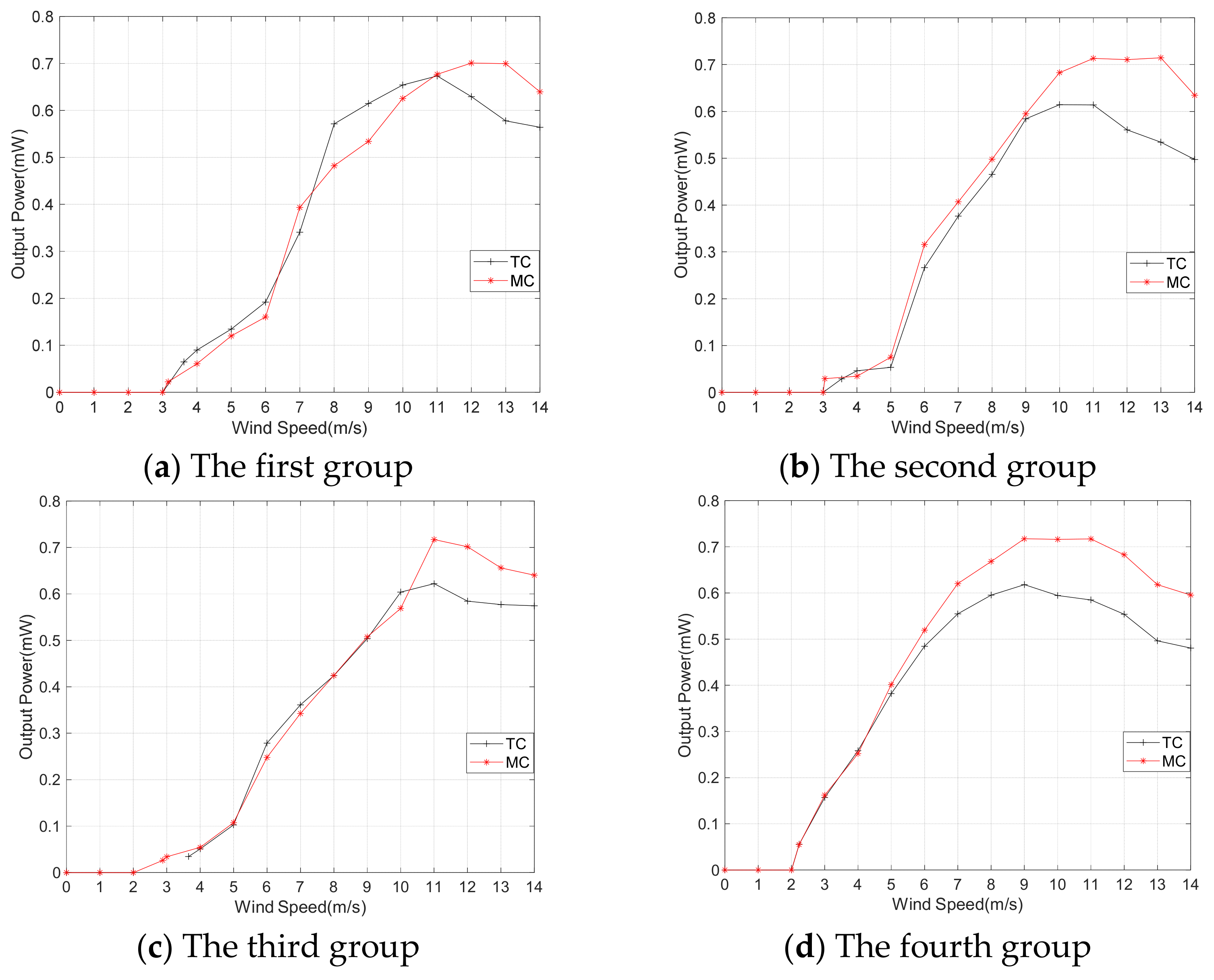
3.1.2. The Output Response of the TC
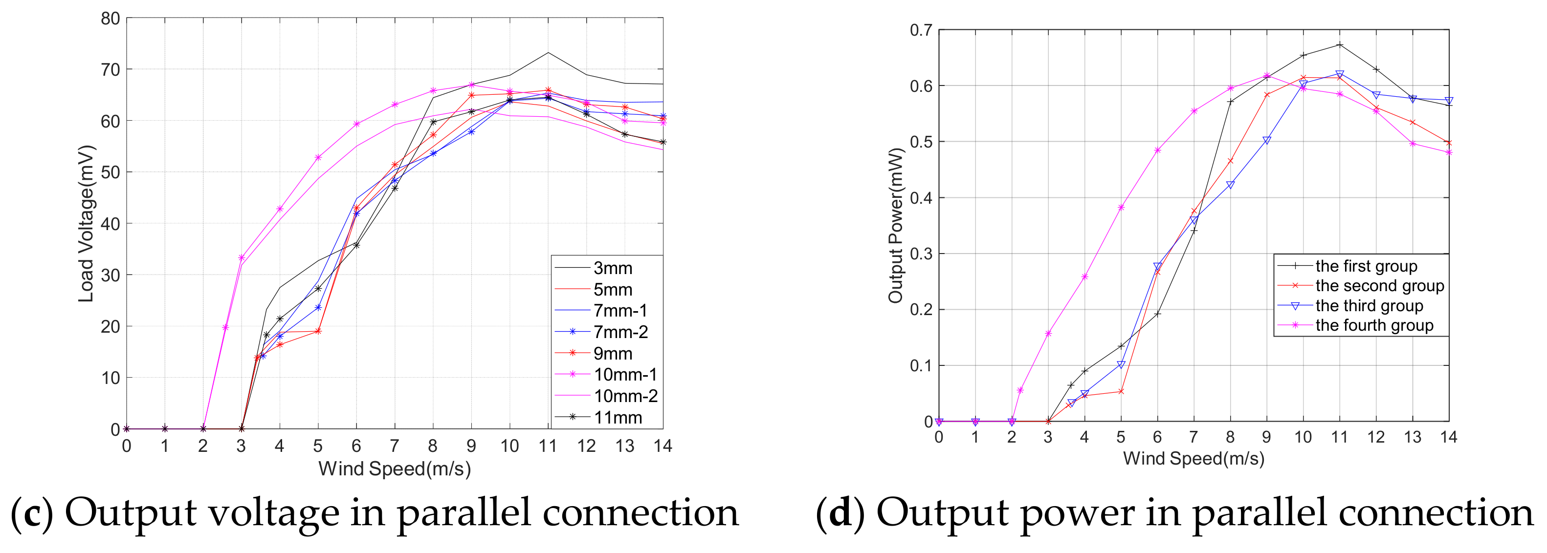
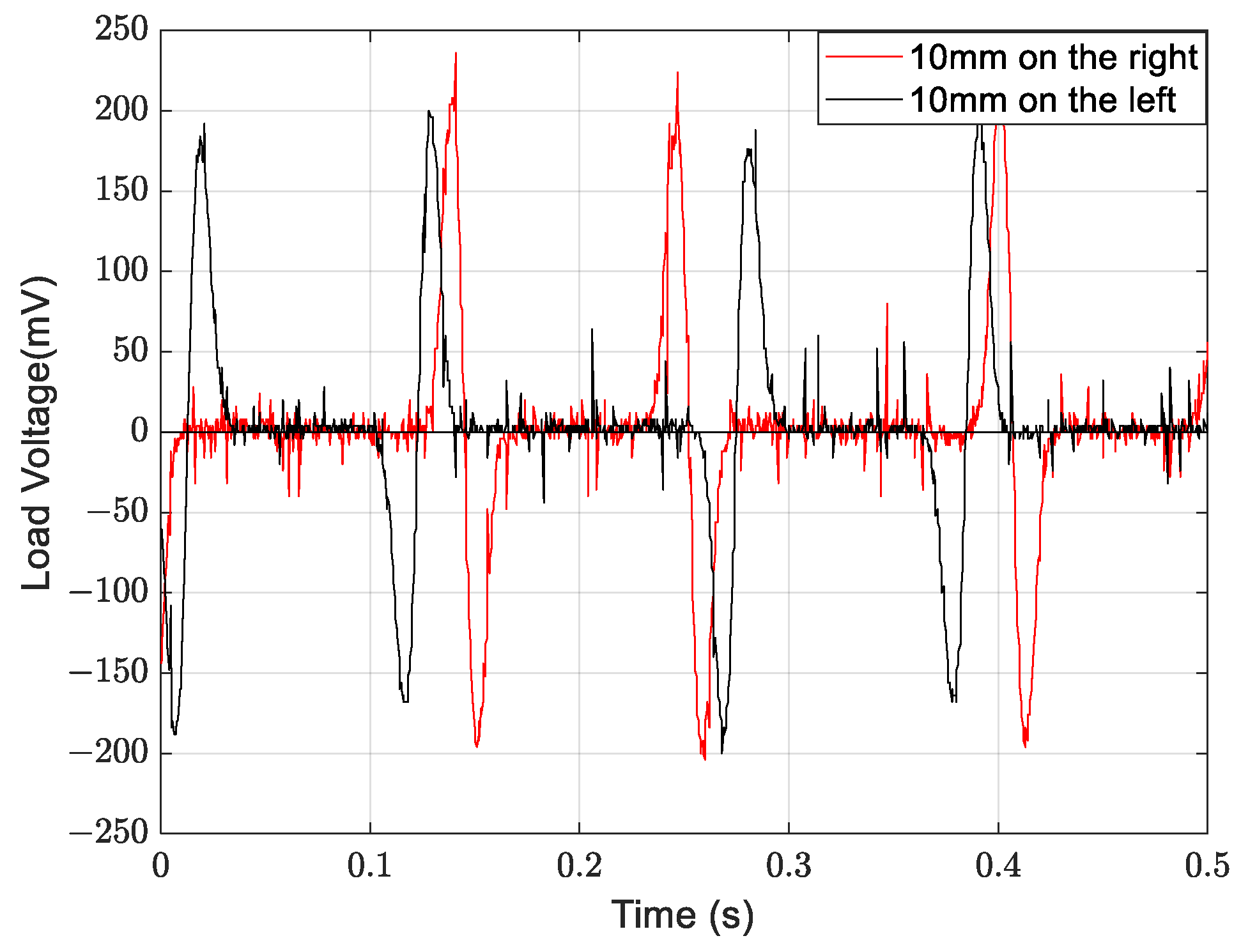
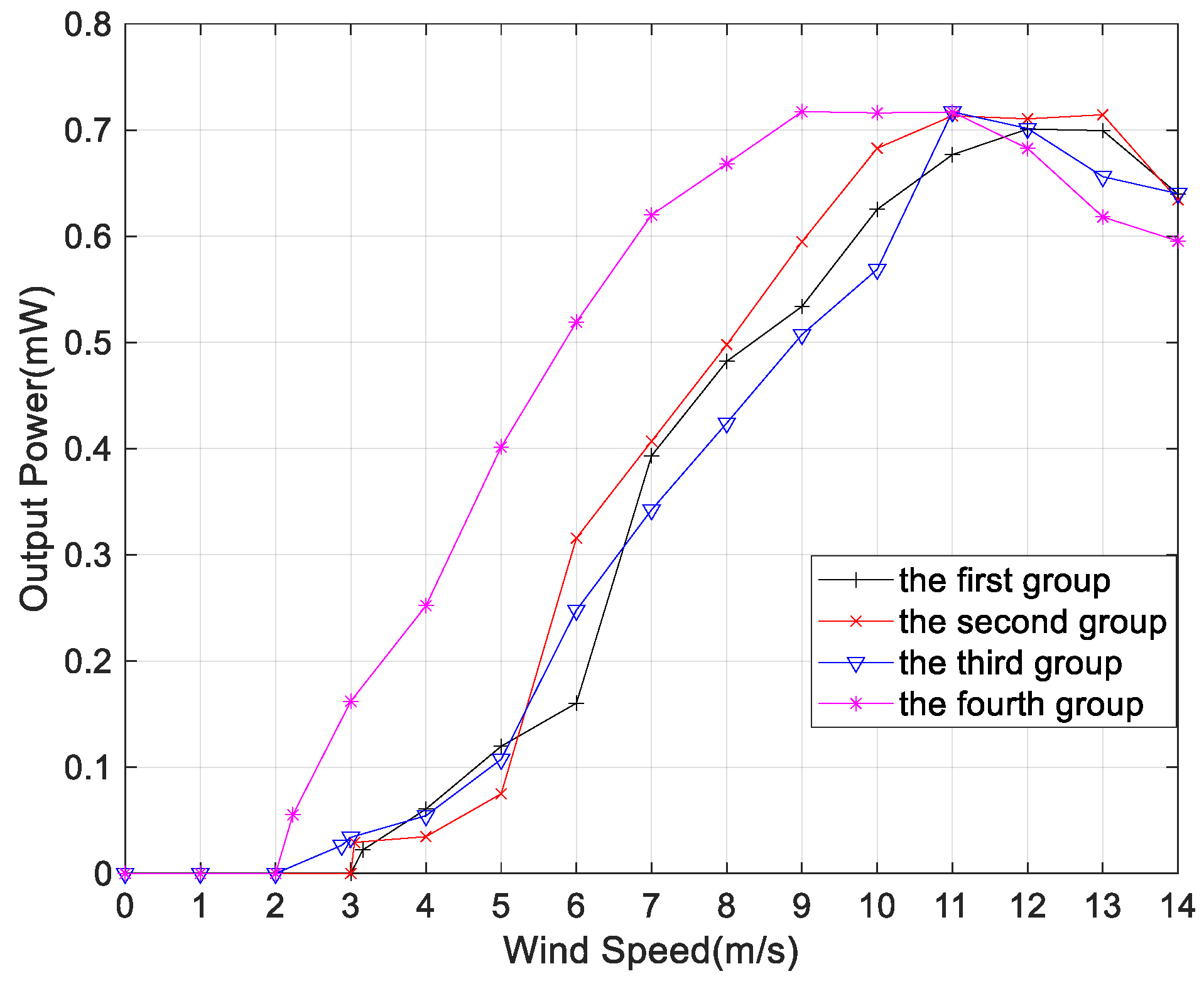
3.1.3. The output Response of MC
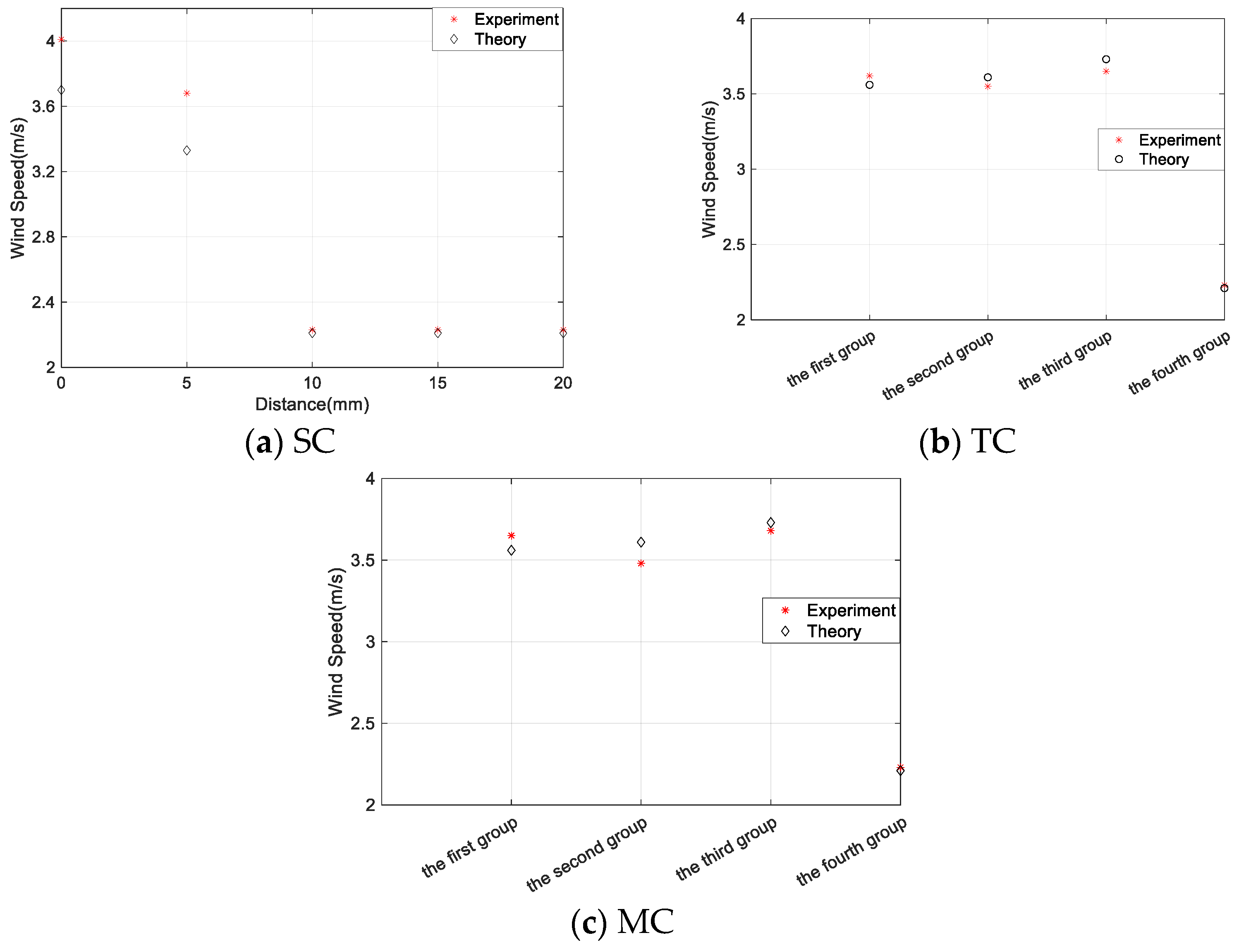
3.2. Critical Wind Speed of the MEGEH
4. Conclusions
Author Contributions
Funding
Data Availability Statement
Conflicts of Interest
References
- Ding, L.; Mao, X.; Yang, L.; Yan, B.; Wang, J.; Zhang, L. Effects of installation position of fin-shaped rods on wind-induced vibration and energy harvesting of aeroelastic energy converter. Smart Mater. Struct. 2021, 30, 025026. [Google Scholar] [CrossRef]
- Lai, Z.; Wang, S.; Zhu, L.; Zhang, G.; Wang, J.; Yang, K.; Yurchenko, D. A hybrid piezo-dielectric wind energy harvester for high-performance vortex-induced vibration energy harvesting. Mech. Syst. Signal Process. 2021, 150, 107212. [Google Scholar] [CrossRef]
- Wang, J.; Zhou, S.; Zhang, Z.; Yurchenko, D. High-performance piezoelectric wind energy harvester with Y-shaped attachments. Energy Convers. Manag. 2019, 181, 645–652. [Google Scholar] [CrossRef]
- Liu, J.; Zuo, H.; Xia, W.; Luo, Y.; Yao, D.; Chen, Y.; Wang, K.; Li, Q. Wind energy harvesting using piezoelectric macro fiber composites based on flutter mode. Microelectron. Eng. 2020, 231, 111333. [Google Scholar] [CrossRef]
- Lu, Z.; Wen, Q.; He, X.; Wen, Z. A Flutter-Based Electromagnetic Wind Energy Harvester: Theory and Experiments. Appl. Sci. 2019, 9, 4823. [Google Scholar] [CrossRef]
- Shan, X.; Tian, H.; Cao, H.; Xie, T. Enhancing Performance of a Piezoelectric Energy Harvester System for Concurrent Flutter and Vortex-Induced Vibration. Energies 2020, 13, 3101. [Google Scholar] [CrossRef]
- Yang, X.; He, X.; Li, J.; Jiang, S. Modeling and verification of piezoelectric wind energy harvesters enhanced by interaction between vortex-induced vibration and galloping. Smart Mater. Struct. 2019, 28, 115027. [Google Scholar] [CrossRef]
- Parkinson, G.V.; Smith, J.D. The Square Prism as an Aeroelastic Non-Linear Oscillator. Q. J. Mech. Appl. Math. 1964, 2, 225–239. [Google Scholar] [CrossRef]
- Parkinson, G.V.; Brooks, N.P.H. On the Aeroelastic Instability of Bluff Cylinders. J. Appl. Mech. 1961, 28, 252–258. [Google Scholar] [CrossRef]
- Barrero-Gil, A.; Alonso, G.; Sanz-Andres, A. Energy harvesting from transverse galloping. J. Sound Vib. 2010, 329, 2873–2883. [Google Scholar] [CrossRef]
- Gao, S.; Zeng, X.; Li, J.; Feng, S.; Chen, Y. Capturing Energy From Power Transmission Lines Galloping and Self-Powered Sensing of Galloping State Through a Rotary Structural Electromagnetic Energy Harvester. IEEE Trans. Energy Convers. 2023, 38, 1855–1867. [Google Scholar] [CrossRef]
- Kim, H.; Kim, S.; Xue, K.; Seok, J. Modeling and performance analysis of electromagnetic energy harvester based on torsional galloping phenomenon. Mech. Syst. Signal Process. 2023, 195, 110287. [Google Scholar] [CrossRef]
- Zhou, M.; Chen, Q.; Xu, Z.; Wang, W. Piezoelectric wind energy harvesting device based on the inverted cantilever beam with leaf-inspired extensions. AIP Adv. 2019, 9, 035213. [Google Scholar] [CrossRef]
- Tan, T.; Hu, X.; Yan, Z.; Zou, Y.; Zhang, W. Piezoelectromagnetic synergy design and performance analysis for wind galloping energy harvester. Sens. Actuators A Phys. 2020, 302, 111813. [Google Scholar] [CrossRef]
- Wang, J.; Tang, L.; Zhao, L.; Zhang, Z. Efficiency investigation on energy harvesting from airflows in HVAC system based on galloping of isosceles triangle sectioned bluff bodies. Energy 2019, 172, 1066–1078. [Google Scholar] [CrossRef]
- Wang, L.; Tan, T.; Yan, Z.; Yan, Z. Tapered galloping energy harvester for power enhancement and vibration reduction. J. Intell. Mater. Syst. Struct. 2019, 30, 2853–2869. [Google Scholar] [CrossRef]
- Sirohi, J.; Mahadik, R. Harvesting Wind Energy Using a Galloping Piezoelectric Beam. J. Vib. Acoust. 2012, 134, 011009. [Google Scholar] [CrossRef]
- Sirohi, J.; Mahadik, R. Piezoelectric wind energy harvester for low-power sensors. J. Intell. Mater. Syst. Struct. 2011, 22, 2215–2228. [Google Scholar] [CrossRef]
- Yang, Y.; Zhao, L.; Tang, L. Comparative study of tip cross-sections for efficient galloping energy harvesting. Appl. Phys. Lett. 2013, 102, 064105. [Google Scholar] [CrossRef]
- Wang, J.; Geng, L.; Zhou, S.; Zhang, Z.; Lai, Z.; Yurchenko, D. Design, modeling and experiments of broadband tristable galloping piezoelectric energy harvester. Acta Mech. Sin. 2020, 36, 592–605. [Google Scholar] [CrossRef]
- Zhang, H.; Zhang, L.; Wang, Y.; Yang, X.; Song, R.; Sui, W. Modeling and experimental investigation of asymmetric distance with magnetic coupling based on galloping piezoelectric energy harvester. Smart Mater. Struct. 2022, 31, 065007. [Google Scholar] [CrossRef]
- Sun, W.; Jang, H.; Seok, J. Magnetically coupled piezoelectric galloping-based energy harvester using a tandem configuration. Mech. Syst. Signal Process. 2021, 161, 107952. [Google Scholar] [CrossRef]
- Hu, G.; Wang, J.; Qiao, H.; Zhao, L.; Li, Z.; Tang, L. An experimental study of a two-degree-of-freedom galloping energy harvester. Int. J. Energy Res. 2020, 45, 3365–3374. [Google Scholar] [CrossRef]
- Zhao, L.; Yang, Y. An impact-based broadband aeroelastic energy harvester for concurrent wind and base vibration energy harvesting. Appl. Energy 2018, 212, 233–243. [Google Scholar] [CrossRef]
- Ewere, F.; Wang, G.; Cain, B. Experimental investigation of galloping piezoelectric energy harvesters with square bluff bodies. Smart Mater. Struct. 2014, 23, 104012. [Google Scholar] [CrossRef]
- Li, X.; Bi, C.; Li, Z.; Liu, B.; Wang, T.; Zhang, S. A Piezoelectric and Electromagnetic Hybrid Galloping Energy Harvester with the Magnet Embedded in the Bluff Body. Micromachines 2021, 12, 626. [Google Scholar] [CrossRef] [PubMed]
- Dai, H.L.; Abdelkefi, A.; Javed, U.; Wang, L. Modeling and performance of electromagnetic energy harvesting from galloping oscillations. Smart Mater. Struct. 2015, 24, 045012. [Google Scholar] [CrossRef]
- Zhang, L.B.; Dai, H.L.; Abdelkefi, A.; Lin, S.X.; Wang, L. Theoretical modeling, wind tunnel measurements, and realistic environment testing of galloping-based electromagnetic energy harvesters. Appl. Energy 2019, 254, 113737. [Google Scholar] [CrossRef]
- Le, H.D.; Kwon, S.-D. An electromagnetic galloping energy harvester with double magnet design. Appl. Phys. Lett. 2019, 115, 133901. [Google Scholar] [CrossRef]
- Le, H.D.; Kwon, S.-D. Design and Experiments of a Galloping-Based Wind Energy Harvester Using Quadruple Halbach Arrays. Energies 2021, 14, 6094. [Google Scholar] [CrossRef]
- Li, X.; Ma, T.; Liu, B.; Wang, C.; Su, Y. Experimental Study on Magnetic Coupling Piezoelectric-Electromagnetic Composite Galloping Energy Harvester. Sensors 2022, 22, 8241. [Google Scholar] [CrossRef] [PubMed]
- Dai, H.L.; Yang, Y.W.; Abdelkefi, A.; Wang, L. Nonlinear analysis and characteristics of inductive galloping energy harvesters. Commun. Nonlinear Sci. Numer. Simul. 2018, 59, 580–591. [Google Scholar] [CrossRef]
- Wacharasindhu, T.; Kwon, J.W. A micromachined energy harvester from a keyboard using combined electromagnetic and piezoelectric conversion. J. Micromech. Microeng. 2008, 18, 104016. [Google Scholar] [CrossRef]
- Xiong, L.; Gao, S.; Jin, L.; Guo, S.; Sun, Y.; Liu, F. The Design and Experiment of a Spring-Coupling Electromagnetic Galloping Energy Harvester. Micromachines 2023, 14, 968. [Google Scholar] [CrossRef]
- Païdoussis, M.P.; Price, S.J.; De Langre, E. Fluid-Structure Interactions: Cross-Flow-Induced Instabilities; Cambridge University Press: New York, NY, USA, 2011. [Google Scholar]


| Structure | Parameters | Value |
|---|---|---|
| Bluff body | h × d × d (mm) | 35 × 15 × 15 |
| Magnet | Remanent flux density (T) | 0.34 |
| Diameter(mm) | 10 | |
| Thickness (mm) | 4 | |
| Elastic beam | Young modulus (GPa) | 110 |
| Dimensions (mm) | 63 × 10 × 0.15 | |
| Poisson ratio | 0.34 | |
| stiffness coefficient K | 6.9 | |
| Coil | Wire diameter (mm)s | 0.2 |
| Height (mm) | 10 | |
| Inner diameter (mm) | 10 | |
| Coil turn | 300 | |
| Outer diameter (mm) | 12.3 | |
| Resistance (Ω) | 13.2 | |
| Aerodynamic coefficient | A1 | 2.69 |
| A3 | −168.4 | |
| The gap between the coil and the bluff body | (mm) | 1.0 |
| Wind speeds (m/s) | 4.08 | 5 | 6 | 7 | 8 | 9 | 10 | 11 | 12 | 13 | 14 |
| Amplitude (mm) | 14.7 | 18.4 | 22.7 | 25.8 | 27.1 | 27.7 | 28.2 | 28.7 | 29.6 | 30 | 30.3 |
| Group | Position |
|---|---|
| The first group | S1 = 3 mm, S2 = 11 mm |
| The second group | S1 = 5 mm, S2 = 9 mm |
| The third group | S1 = 7 mm, S2 = 7 mm |
| The fourth group | S1 = 10 mm, S2 = 10 mm |
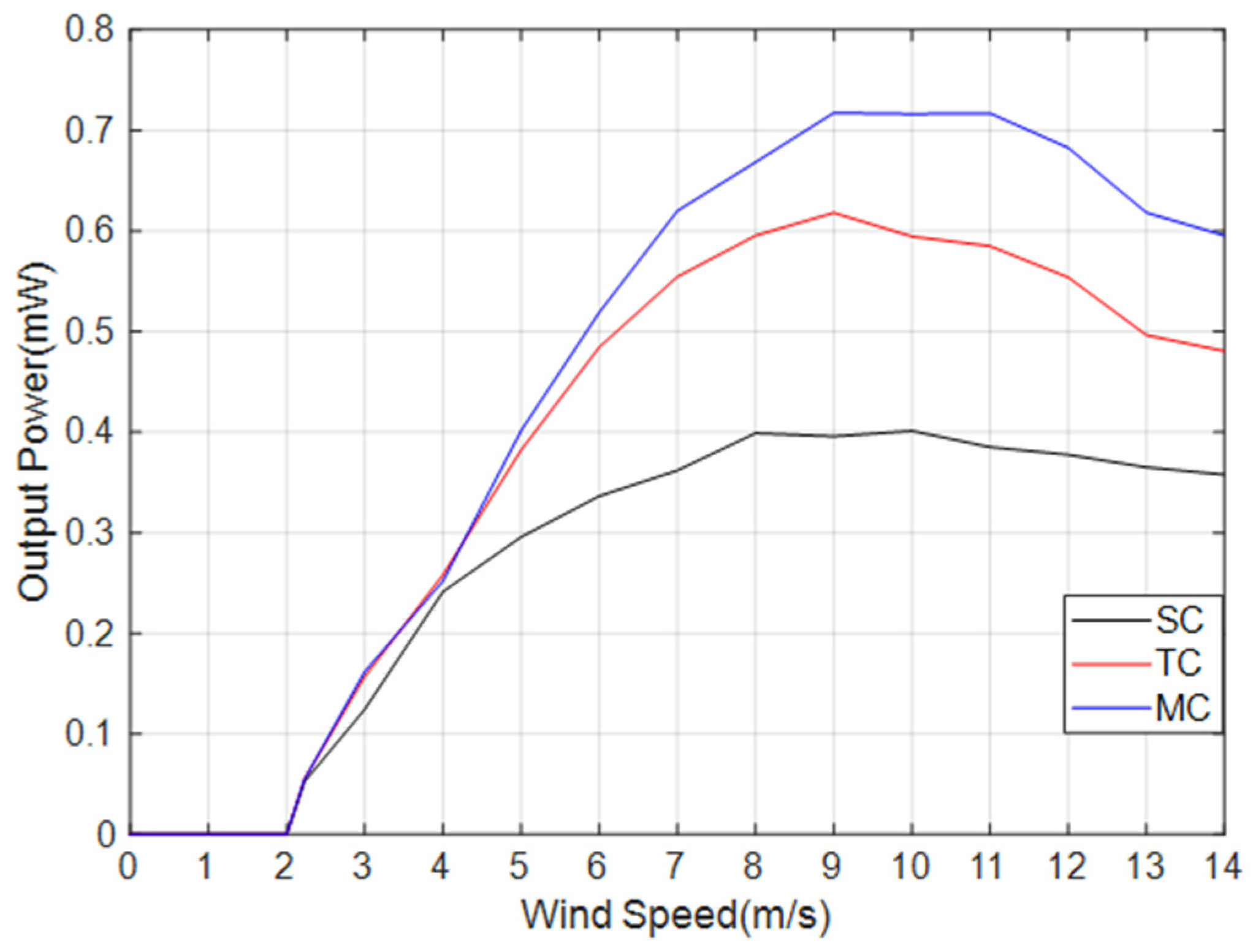
| Wind Speed (m/s) | 2.23 | 3 | 4 | 5 | 6 | 7 | 8 | 9 | 10 | 11 | 12 | 13 | 14 |
|---|---|---|---|---|---|---|---|---|---|---|---|---|---|
| TC | 0.06 | 0.16 | 0.26 | 0.38 | 0.48 | 0.55 | 0.6 | 0.62 | 0.59 | 0.58 | 0.55 | 0.5 | 0.48 |
| SC | 0.05 | 0.12 | 0.24 | 0.3 | 0.34 | 0.36 | 0.4 | 0.4 | 0.4 | 0.39 | 0.38 | 0.37 | 0.36 |
| Group | Position |
|---|---|
| The first group | S1 = 3 mm, S2 = 11 mm, S3 = 14 mm |
| The second group | S1 = 5 mm, S2 = 9 mm, S3 = 14 mm |
| The third group | S1 = 7 mm, S2 = 7 mm, S3 = 14 mm |
| The fourth group | S1 = 10 mm, S2 = 10 mm, S3 = 14 mm |
Disclaimer/Publisher’s Note: The statements, opinions and data contained in all publications are solely those of the individual author(s) and contributor(s) and not of MDPI and/or the editor(s). MDPI and/or the editor(s) disclaim responsibility for any injury to people or property resulting from any ideas, methods, instructions or products referred to in the content. |
© 2023 by the authors. Licensee MDPI, Basel, Switzerland. This article is an open access article distributed under the terms and conditions of the Creative Commons Attribution (CC BY) license (https://creativecommons.org/licenses/by/4.0/).
Share and Cite
Xiong, L.; Gao, S.; Jin, L.; Sun, Y.; Du, X.; Liu, F. Study on the Influence of Coil Arrangement on the Output Characteristics of Electromagnetic Galloping Energy Harvester. Micromachines 2023, 14, 2158. https://doi.org/10.3390/mi14122158
Xiong L, Gao S, Jin L, Sun Y, Du X, Liu F. Study on the Influence of Coil Arrangement on the Output Characteristics of Electromagnetic Galloping Energy Harvester. Micromachines. 2023; 14(12):2158. https://doi.org/10.3390/mi14122158
Chicago/Turabian StyleXiong, Lei, Shiqiao Gao, Lei Jin, Yaoqiang Sun, Xueda Du, and Feng Liu. 2023. "Study on the Influence of Coil Arrangement on the Output Characteristics of Electromagnetic Galloping Energy Harvester" Micromachines 14, no. 12: 2158. https://doi.org/10.3390/mi14122158
APA StyleXiong, L., Gao, S., Jin, L., Sun, Y., Du, X., & Liu, F. (2023). Study on the Influence of Coil Arrangement on the Output Characteristics of Electromagnetic Galloping Energy Harvester. Micromachines, 14(12), 2158. https://doi.org/10.3390/mi14122158