

Cascaded 2D Micromirror with Application to LiDAR


Abstract
:1. Introduction
2. Design
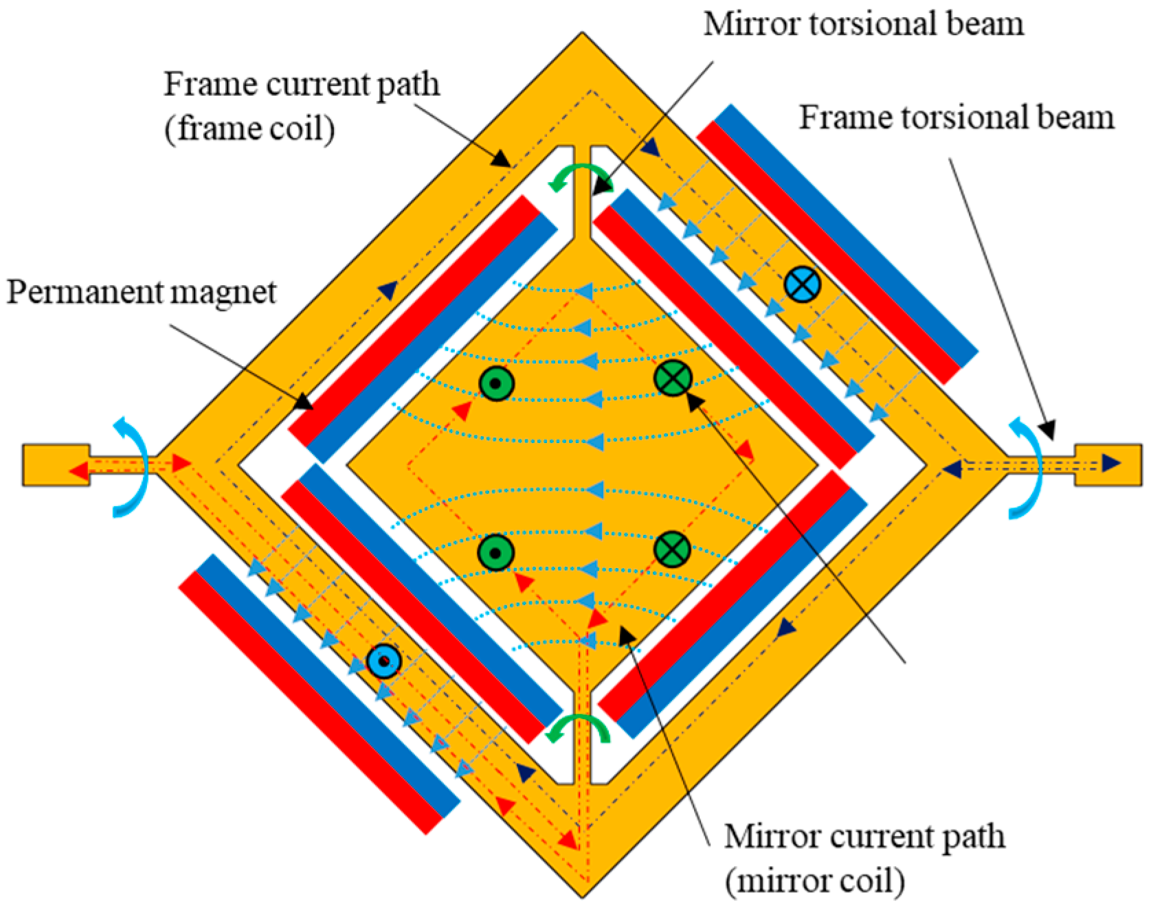
- In the prior cascaded designs, only the inner torsional beam is responsible for actuation, with the outer torsional beam remaining significantly stiffer and nearly stationary. In contrast, the proposed design involves both torsional beams in actuation, and the ratio of torsional stiffness between them is considerably less significant and under control.
- Previous cascaded designs generated actuating torque solely on the outer gimbal, whereas in the proposed design, both gimbals are utilized to generate torque.
- While the earlier cascaded designs were limited to resonance actuation, the proposed cascaded design offers the flexibility of actuation in either resonance or quasi-static modes.
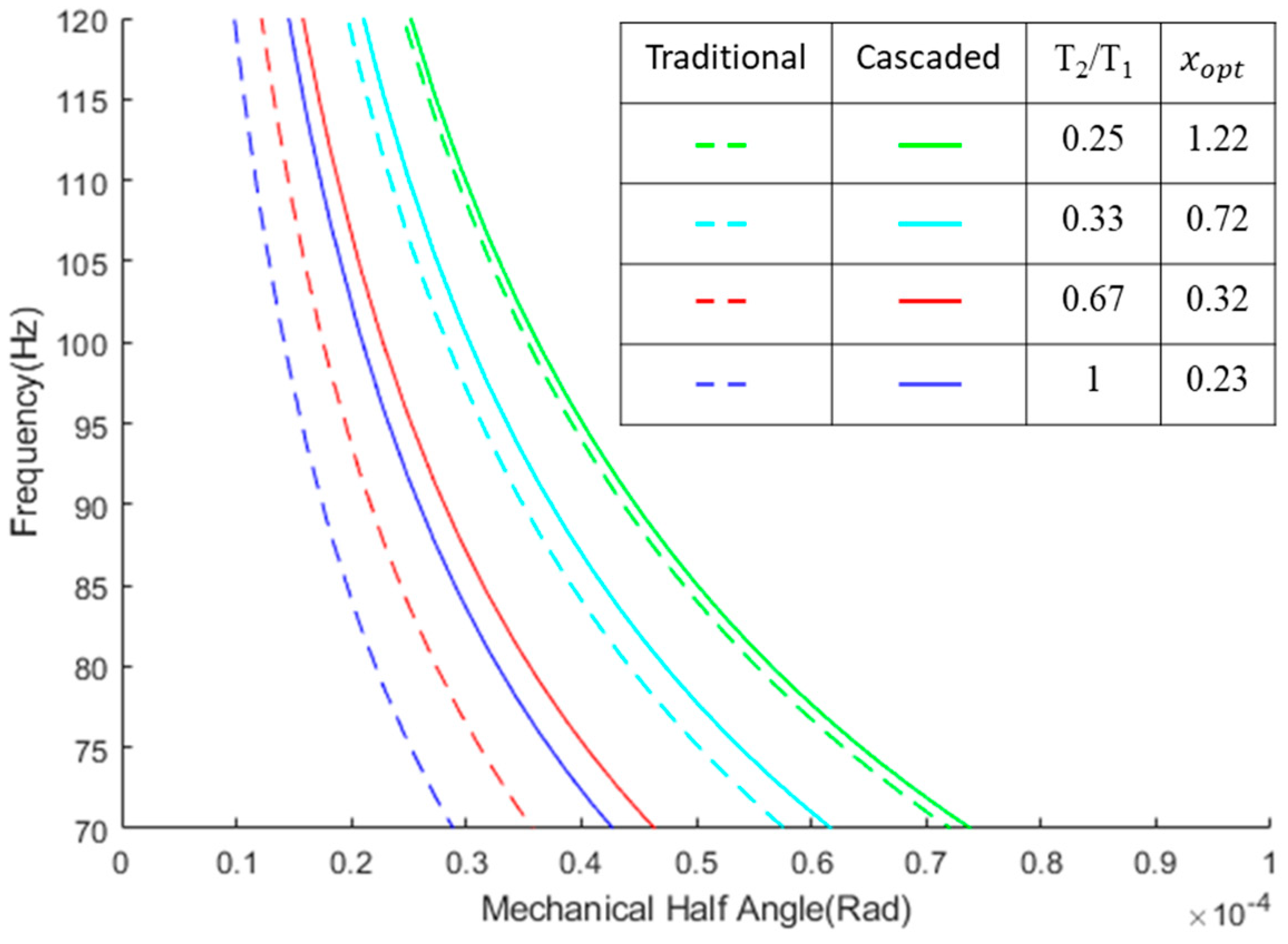
- Most importantly, the problem addressed by the proposed design differs from that of previous methods. Previous cascaded designs aimed to reduce the number of torsional beams containing current-carrying wires and increase torque for small micromirrors alongside heat control in the reflective layer. In contrast, the proposed cascaded design focuses on optimizing the trade-off between resonance frequency and actuation angle for large aperture micromirrors.
2.1. Theoretical Analysis
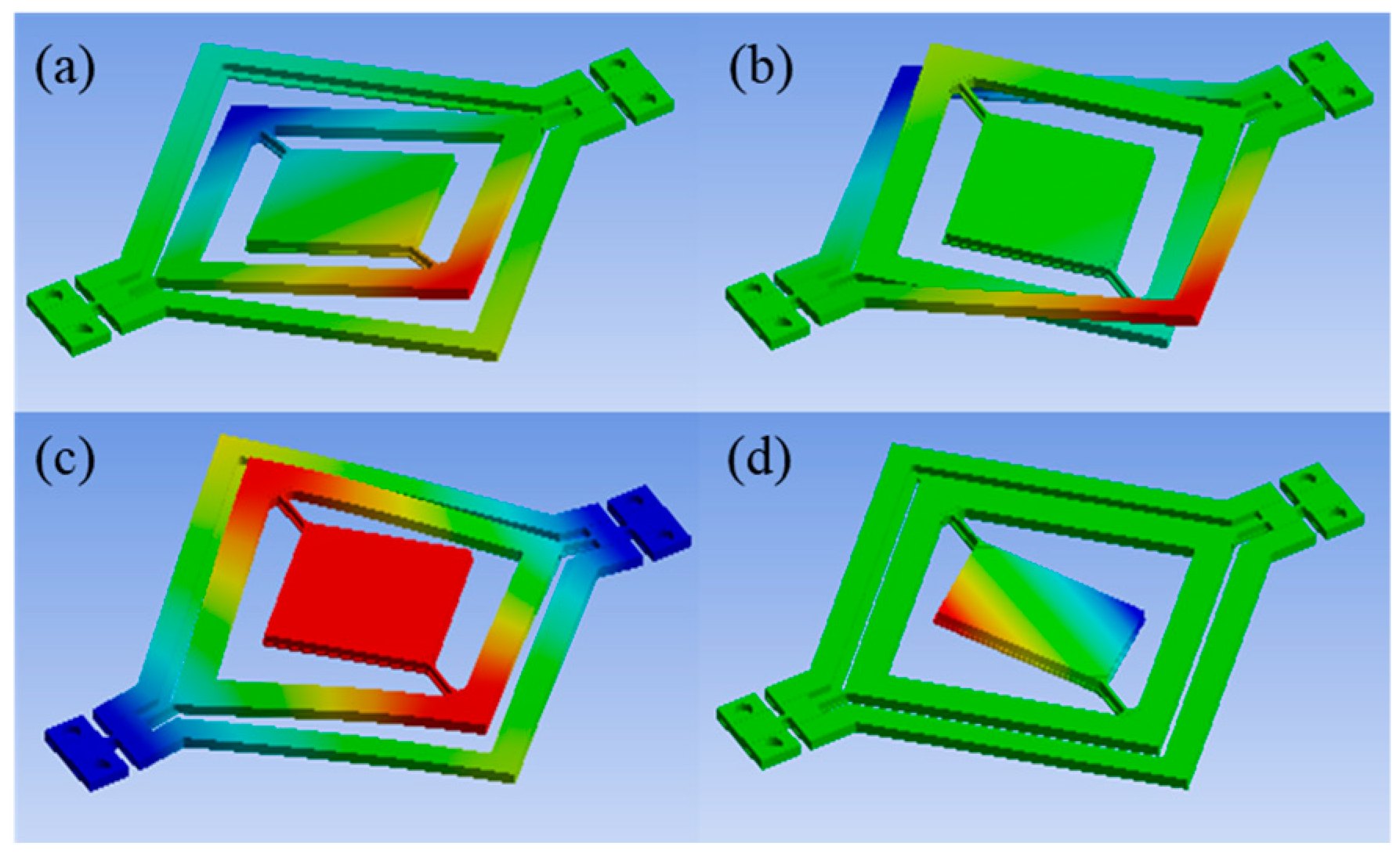
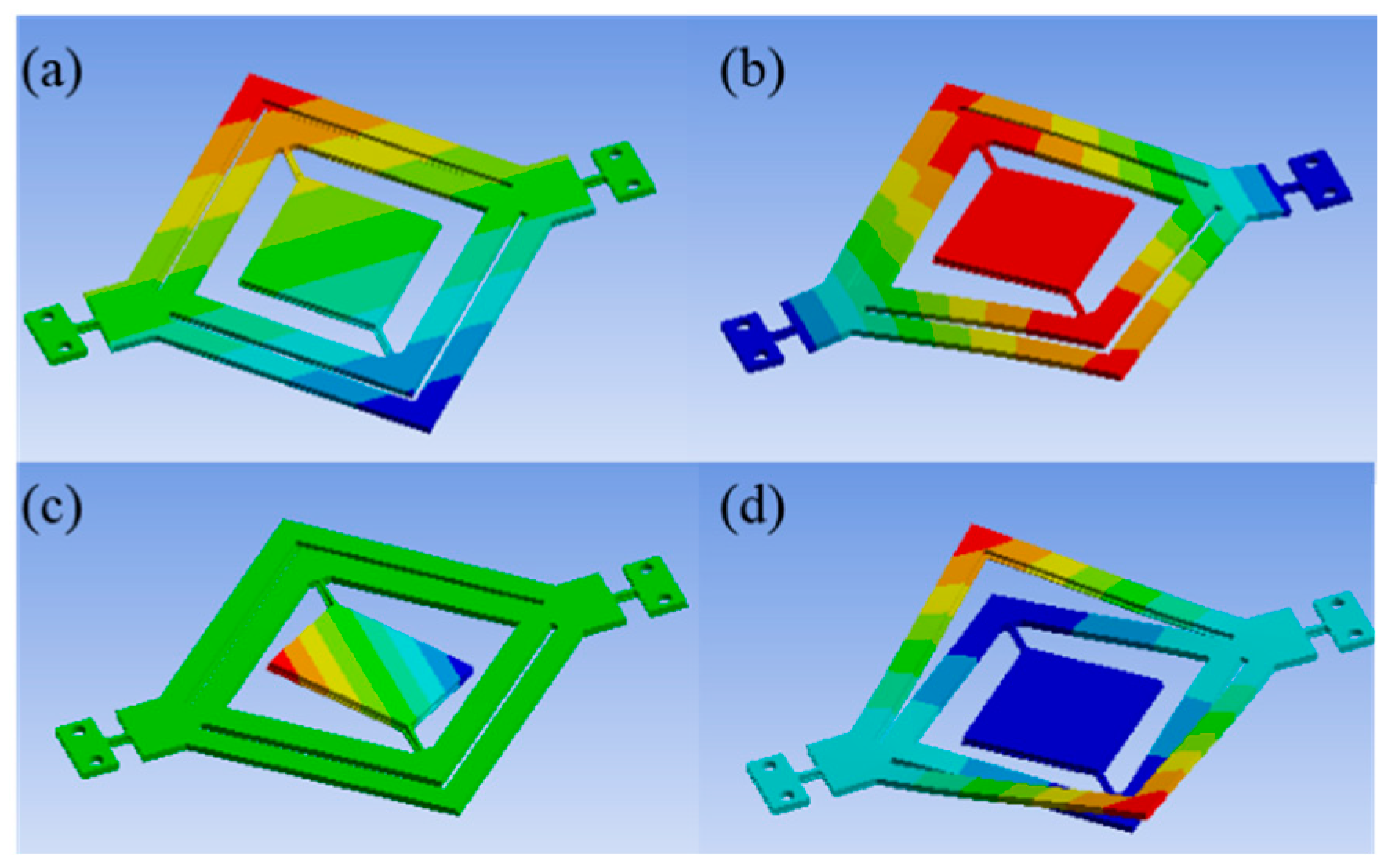
2.2. Modelling and Simulation
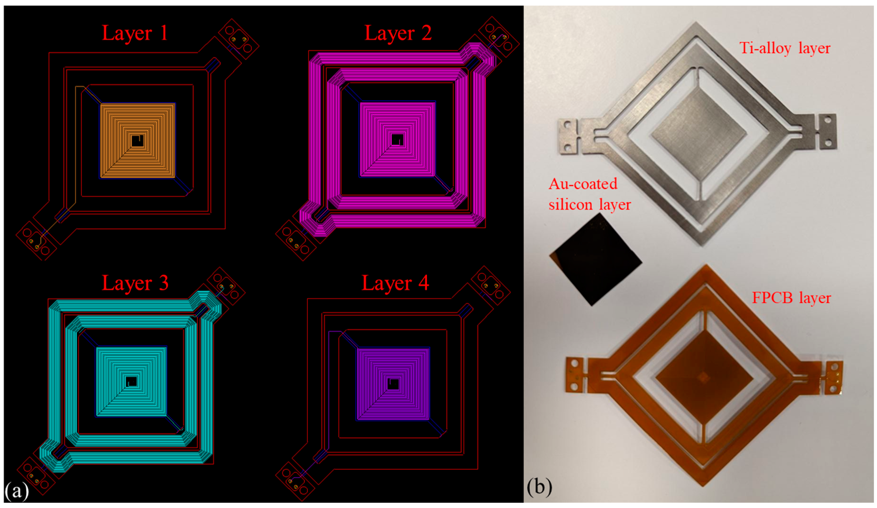
3. Fabrication
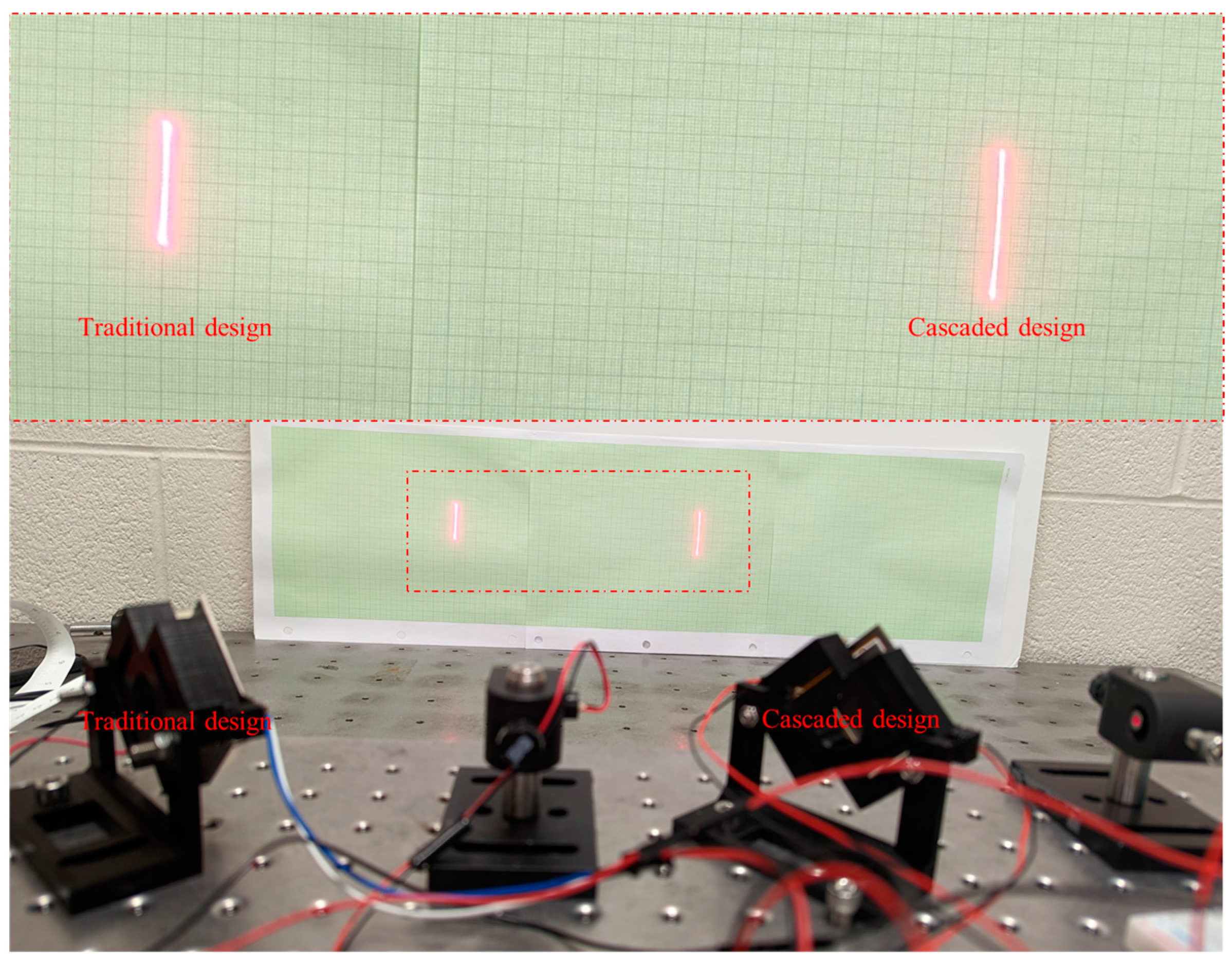
4. Testing
5. Application of the Cascaded 2D Micromirror to LIDAR
6. Summary and Discussion
7. Conclusions
Author Contributions
Funding
Data Availability Statement
Acknowledgments
Conflicts of Interest
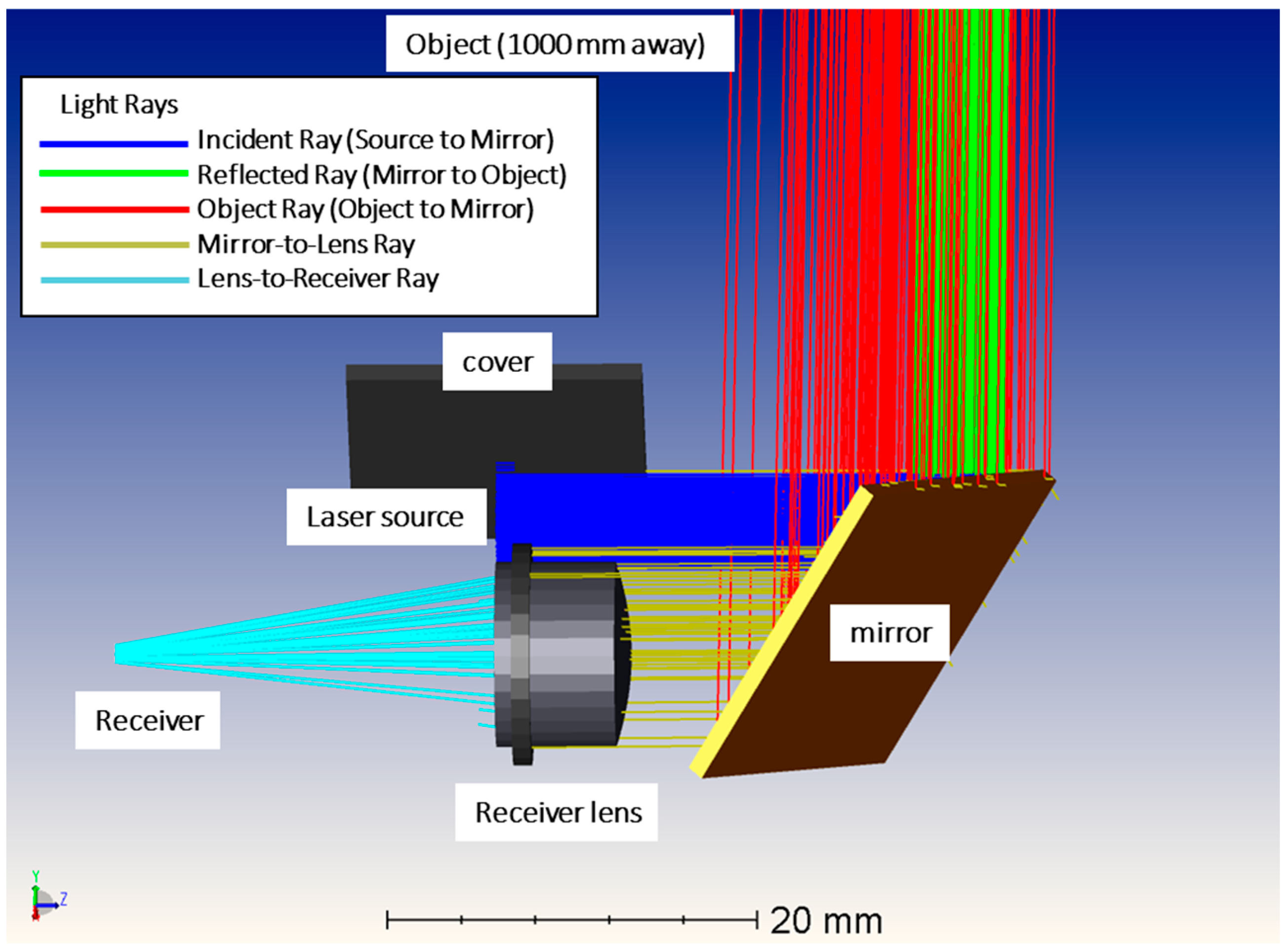
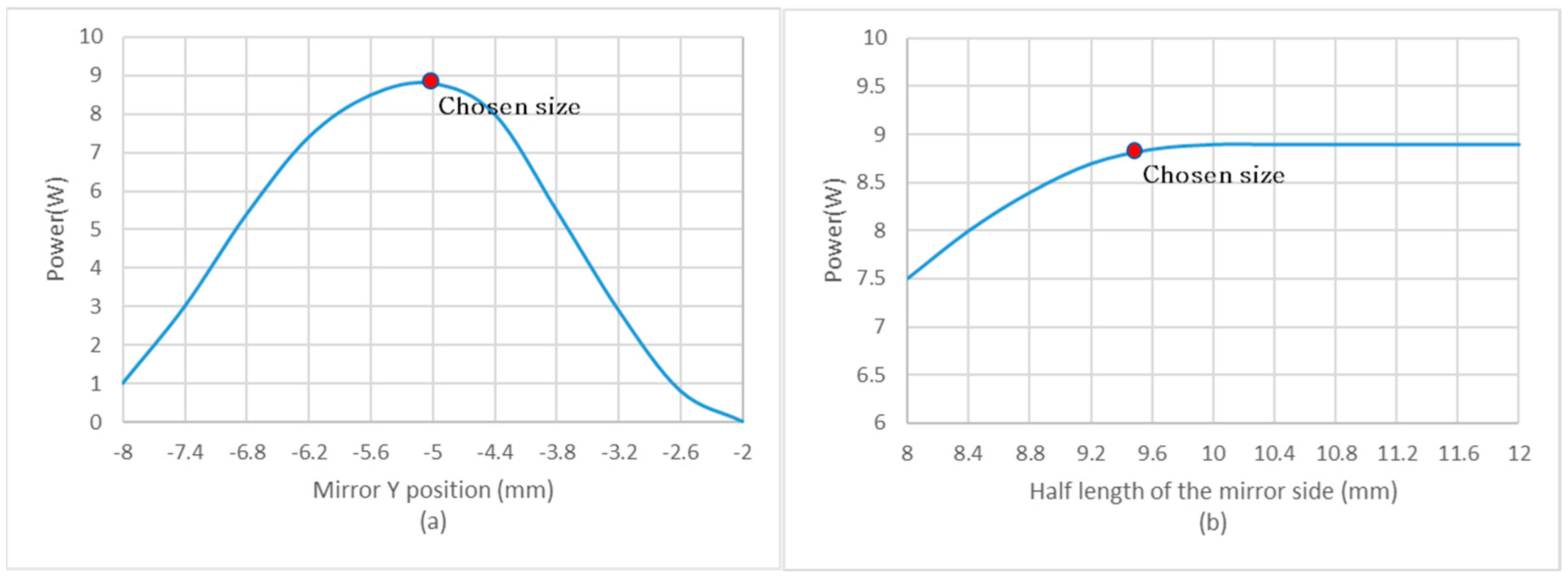
Appendix A. LiDAR Setup Optimization Using Zemax OpticStudio


References
- Li, Y.; Ibanez-Guzman, J. Lidar for autonomous driving: The principles, challenges, and trends for automotive lidar and perception systems. IEEE Signal Process. Mag. 2020, 37, 50–61. [Google Scholar] [CrossRef]
- Rablau, C. LIDAR—A new (self-driving) vehicle for introducing optics to broader engineering and non-engineering audiences. In Proceedings of the Education and Training in Optics and Photonics, Quebec City, QC, Canada, 21–24 May 2019; Optical Society of America: California, CA, USA, 2019; p. 11143_138. [Google Scholar]
- Yang, T.; Li, Y.; Zhao, C.; Yao, D.; Chen, G.; Sun, L.; Krajnik, T.; Yan, Z. 3D ToF LiDAR in mobile robotics: A review. arXiv 2022, arXiv:2202.11025. [Google Scholar]
- Wang, D.; Watkins, C.; Xie, H. MEMS Mirrors for LiDAR: A review. Micromachines 2020, 11, 456. [Google Scholar] [CrossRef]
- Yalcinkaya, A.D.; Urey, H.; Brown, D.; Montague, T.; Sprague, R. Two-axis electromagnetic microscanner for high resolution displays. J. Microelectromech. Syst. 2006, 15, 786–794. [Google Scholar] [CrossRef]
- Chen, M.; Yu, H.; Guo, S.; Xu, R.; Shen, W. An electromagnetically-driven MEMS micromirror for laser projection. In Proceedings of the 10th IEEE International Conference on Nano/Micro Engineered and Molecular Systems, Xi’an, China, 7–11 April 2015; IEEE: New York, NY, USA, 2015; pp. 605–607. [Google Scholar]
- Petrak, O.; Schwarz, F.; Pohl, L.; Reher, M.; Janicke, C.; Przytarski, J.; Senger, F.; Albers, J.; Giese, T.; Ratzmann, L. Laser beam scanning based AR-display applying resonant 2D MEMS mirrors. In Proceedings of the Optical Architectures for Displays and Sensing in Augmented, Virtual, and Mixed Reality (AR, VR, MR) II, Xi’an, China, 7–11 April 2015; SPIE: Philadelphia, PA, USA, 2021; pp. 15–32. [Google Scholar]
- Wang, Z.; Xie, T.; Pan, Y. MEMS-based endoscopic optical coherence tomography. In Proceedings of the Biomedical Topical Meeting, Miami Beach, FL, USA, 14–17 April 2004; Optica Publishing Group: Washington, DC, USA, 2004; p. FH34. [Google Scholar]
- Zolfaghari, P.; Khodapanahandeh, M.; Urey, H.; Ferhanoglu, O. Cascaded laser scanning towards high-resolution LiDAR. Opt. Laser Technol. 2024, 168, 109906. [Google Scholar] [CrossRef]
- Xu, F.; Qiao, D.; Song, X.; Zheng, W.; He, Y.; Fan, Q. A Semi-coaxial MEMS-based LiDAR. In Proceedings of the IECON 2019—45th Annual Conference of the IEEE Industrial Electronics Society, Lisbon, Portugal, 14–17 October 2019; IEEE: New York, NY, USA, 2019; pp. 6726–6731. [Google Scholar]
- Bissonnette, L.R. Multiple-scattering lidar equation. Appl. Opt. 1996, 35, 6449–6465. [Google Scholar] [CrossRef]
- Zuo, H.; He, S. Extra Large Aperture FPCB Mirror Based Scanning LiDAR. IEEE/ASME Trans. Mechatron. 2021, 27, 93–102. [Google Scholar] [CrossRef]
- Tai, T.S.; Zuo, H.; He, S. 3D LIDAR based on FPCB mirror. Mechatronics 2022, 82, 102720. [Google Scholar] [CrossRef]
- Tai, T.; He, S.; Ghazinouri, B. 2D FPCB micromirror for scanning LIDAR. J. Micromech. Microeng. 2022, 33, 125001. [Google Scholar] [CrossRef]
- Ghazinouri, B.; He, S. Crosstalk-free large aperture size 2D gimbal micromirror. In Proceedings of the IEEE MEMS Conference Munich 2023, Munich, Germany, 15–19 January 2023; IEEE: New York, NY, USA, 2023. [Google Scholar]
- Ghazinouri, B.; He, S. Crosstalk-free large aperture electromagnetic 2D micromirror for LiDAR application. J. Micromech. Microeng. 2023, 33, 095005. [Google Scholar] [CrossRef]
- Yoo, H.W.; Brunner, D.; Macho, M.; Niedermueller, L.; Devesa, A.J.; Kormann, L.; Schitter, G. Evaluation of robustness against external vibrations for long-range MEMS lidar with one-dimensional resonant micromirror. J. Opt. Microsyst. 2022, 2, 011007. [Google Scholar] [CrossRef]
- Hua, Y.; Wang, S.; Li, B.; Bai, G.; Zhang, P. Dynamic modeling and anti-disturbing control of an electromagnetic MEMS torsional micromirror considering external vibrations in vehicular LiDAR. Micromachines 2021, 12, 69. [Google Scholar] [CrossRef]
- Senger, F.; Hofmann, U.; von Wantoch, T.; Mallas, C.; Janes, J.; Benecke, W.; Herwig, P.; Gawlitza, P.; Delgado, M.A.O.; Grune, C. Centimeter-scale MEMS scanning mirrors for high power laser application. In Proceedings of the MOEMS and Miniaturized Systems XIV, San Francisco, CA, USA, 9–12 February 2015; SPIE: San Francisco, CA, USA, 2015; pp. 27–42. [Google Scholar]
- Nakagawa, W.; Sakaue, S.; Tsuruoka, M. Torsional Vibrators and Light Deflectors Using the Torsional Vibrator. U.S. Patent No. 5,543,956, 6 August 1996. [Google Scholar]
- Kang, S.-Y.; Park, J.-H.; Ji, C.-H. Design optimization of a 6.4 mm-diameter electromagnetic 2D scanning micromirror. Opt. Express 2020, 28, 31272–31286. [Google Scholar] [CrossRef]
- Rao, S.S.; Yap, F.F. Mechanical Vibrations; Addison-Wesley: New York, NY, USA, 2018. [Google Scholar]
- Young, W.C.; Budynas, R.G.; Sadegh, A.M. Roark’s Formulas for Stress and Strain; McGraw-Hill Education: New York, NY, USA, 2012. [Google Scholar]
- Zuo, H.; He, S. FPCB micromirror-based laser projection availability indicator. IEEE Trans. Ind. Electron. 2016, 63, 3009–3018. [Google Scholar] [CrossRef]
- Periyasamy, K.G.; Tan, V.J.; He, S.; Kourtzanidis, N. External electromagnet FPCB micromirror for large angle laser scanning. Micromachines 2019, 10, 667. [Google Scholar] [CrossRef] [PubMed]
- Ghazinouri, B.; He, S.; Tai, T.S. A position sensing method for 2D scanning mirrors. J. Micromech. Microeng. 2022, 32, 045007. [Google Scholar] [CrossRef]
- Tan, V.J.; He, S. Oscillation FPCB micromirror based triangulation laser rangefinder. J. Micromech. Microeng. 2020, 30, 095008. [Google Scholar] [CrossRef]
- Zuo, H.; He, S. FPCB Masked One-Step Etching Large Aperture Mirror for LiDAR. J. Microelectromech. Syst. 2020, 29, 571–584. [Google Scholar] [CrossRef]
- Ye, L.; Zhang, G.; You, Z. Large-aperture kHz operating frequency Ti-alloy based optical micro scanning mirror for LiDAR application. Micromachines 2017, 8, 120. [Google Scholar] [CrossRef]
- Shin, B.H.; Oh, D.; Lee, S.-Y. A two-dimensional laser scanning mirror using motion-decoupling electromagnetic actuators. Sensors 2013, 13, 4146–4156. [Google Scholar] [CrossRef]
- Sandner, T.; Kimme, S.; Grasshoff, T.; Todt, U.; Graf, A.; Tulea, C.; Lenenbach, A.; Schenk, H. Micro-scanning mirrors for high-power laser applications in laser surgery. In Proceedings of the 2013 International Conference on Optical MEMS and Nanophotonics (OMN), Kanazawa, Japan, 18–22 August 2013; IEEE: New York, NY, USA, 2013; pp. 83–84. [Google Scholar]
- Li, F.; Zhou, P.; Wang, T.; He, J.; Yu, H.; Shen, W. A large-size MEMS scanning mirror for speckle reduction application. Micromachines 2017, 8, 140. [Google Scholar] [CrossRef]
- Ataman, Ç.; Lani, S.; Noell, W.; De Rooij, N. A dual-axis pointing mirror with moving-magnet actuation. J. Micromech. Microeng. 2012, 23, 025002. [Google Scholar] [CrossRef]


| Frame Actuation Method | Resonant Frequency () | Mechanical Static Half-Angle of the Frame () |
|---|---|---|
| Cascaded Design [22] | ||
| Traditional Design | ||
| Variables | Torsional stiffnesses: Stiffness ratio: | |
| Constants | Torques: Mass Moment of Inertia: | |
| Symbol | Parameter | Value [Unit] |
|---|---|---|
| Mass moment of inertia of the outer frame | 7.65 × 10⁻⁷ [kgm2] | |
| Mass moment of inertia of the inner frame | 4.53 × 10⁻⁷ [kgm2] | |
| Torque generated on the outer frame | 5.03 × 10⁻⁶ [Nm] | |
| Torque generated on the inner frame | 3.40 × 10⁻⁶ [Nm] |
| Mirror | Mirror Plate Dimension or Diameter (mm) | Horizontal Optical Angle (rad) | Vertical Optical Angle (rad) | Horizontal Resonance Frequency (kHz) | Vertical Resonance Frequency (kHz) | FoM |
|---|---|---|---|---|---|---|
| Cascaded Design | 19 × 19 | 0.28 | 0.08 | 0.29 | 0.13 | 0.55 |
| Traditional Design | 19 × 19 | 0.28 | 0.06 | 0.29 | 0.1 | 0.42 |
| [16] | 19 × 19 | 0.82 | 0.35 | 0.04 | 0.03 | 0.34 |
| [30] | 8 | 1.57 | 0.28 | 0.06 | 0.06 | 0.32 |
| [31] | 5 × 7.1 | 0.37 | 0.03 | 0.61 | 0.26 | 0.25 |
| [32] | 6.5 | 0.27 | 0.16 | 0.67 | 1.87 | 1.49 |
| [21] | 6 | 0.45 | 0.62 | 0.30 | 1.06 | 1.88 |
| [33] | 4 × 4 | 0.56 | 0.56 | 0.16 | 0.17 | 0.37 |
Disclaimer/Publisher’s Note: The statements, opinions and data contained in all publications are solely those of the individual author(s) and contributor(s) and not of MDPI and/or the editor(s). MDPI and/or the editor(s) disclaim responsibility for any injury to people or property resulting from any ideas, methods, instructions or products referred to in the content. |
© 2023 by the authors. Licensee MDPI, Basel, Switzerland. This article is an open access article distributed under the terms and conditions of the Creative Commons Attribution (CC BY) license (https://creativecommons.org/licenses/by/4.0/).
Share and Cite
Ghazinouri, B.; He, S. Cascaded 2D Micromirror with Application to LiDAR. Micromachines 2023, 14, 1954. https://doi.org/10.3390/mi14101954
Ghazinouri B, He S. Cascaded 2D Micromirror with Application to LiDAR. Micromachines. 2023; 14(10):1954. https://doi.org/10.3390/mi14101954
Chicago/Turabian StyleGhazinouri, Behrad, and Siyuan He. 2023. "Cascaded 2D Micromirror with Application to LiDAR" Micromachines 14, no. 10: 1954. https://doi.org/10.3390/mi14101954
APA StyleGhazinouri, B., & He, S. (2023). Cascaded 2D Micromirror with Application to LiDAR. Micromachines, 14(10), 1954. https://doi.org/10.3390/mi14101954