1. Introduction
The fluid thermal conductivity has been used in many scientific and technical sectors, such as microelectronics, transportation, atomic reactors, heat exchangers, cancer therapy, etc. The ordinary base fluids such as water, oils, ethylene glycol and kerosene have a smaller heat transfer phenomenon because of their weaker thermal conductivity. One of the facile ways to escalate the fluid thermal conductivity is to admix the nanoscale (1–100 nm) particles named nanoparticles into the ordinary base fluids to improve their conductivity. Imtiaz et al. [
1] proved that the flow speed is enriched for larger values of the shape parameter and NPVF for the 3D flow of CNTs with the CCHF model. The problem of stagnation point flow of CNTs past a cylinder was analytically solved by Hayat et al. [
2]. It has been proved that the NPVF leads to the development of the skin friction coefficient. Yacob et al. [
3] noticed that the larger size of NPVF generates more heat inside the boundary for the problem of rotating flow of CNTs on a shrinking/stretching surface. The flow of water/kerosene-based CNTs over a moving plate with suction was examined by Anuar et al. [
4]. Their findings unambiguously demonstrate that the SWCNTs have a more significant skin friction coefficient, and MWCNTs have a more considerable heat transfer gradient. Haq et al. [
5] found that the SWCNTs have a bigger heat transfer gradient than the MWCNTs for the problem of the MHD pulsatile flow of CNTs. They consider engine oil as a base fluid.
Electrically conducting fluids play a vital role in nuclear power plants, MHD generators, plasma propulsion in astronautics, geophysics, power plants, astronomy, etc. The steady, MHD and stagnation flow of CNTs past a shrinking/stretching sheet was examined by Anuar et al. [
6]. Their findings clearly demonstrate that the magnetic field parameter leads to an enhancement of the surface shear stress. Manjunatha et al. [
7] examined the MHD flow of water-based CNTs on a rotating disk. It is noted that the fluid thermal profile develops when enhancing the magnetic field parameter. Acharya et al. [
8] noticed a larger magnetic field parameter drop-off of the fluid heat transfer gradient in their study of the MHD flow of CNTs past a deformable sheet. The time-dependent free convective flow of Casson nanofluid past a moving plate with the impact of a magnetic field was discussed by Noranuar et al. [
9]. It is evident from the outcomes that the skin friction coefficient improves when strengthening the magnetic field. The natural convective flow of MHD water-based CNTs was examined by Benos et al. [
10]. Mabood et al. [
11] noticed that the entropy production reduces via a magnetic field in their study of the MHD flow of Jeffrey nanofluid past a SS.
However, in the majority of the aforementioned investigations, the impact of thermal radiation on flow and heat transmission has not been considered. However, when technical procedures are carried out at high temperatures, they become significant and cannot be disregarded. The fluid flow with radiation is noteworthy in many engineering processes that occur at high temperatures in industrial processes. The heat transfer via radiation is essential in producing reliable equipment, nuclear plants, gas turbines, satellites, aircraft, missiles, spacecraft, etc. Mahabaleshwar et al. [
12], in their study of the radiative flow of water-based CNTs past a stretching surface, reported that a higher radiation parameter develops a temperature gradient. The radiative flow of CNTs on a stretching sheet with a magnetic field was investigated by Shah et al. [
13]. Their results unequivocally show that the radiation parameter improves the fluid warmness. Aman et al. [
14] noted from the obtained results that the temperature of SWCNTs is larger than the MWCNTs for the problem of MHD water/kerosene-oil/engine-oil-based CNTs past a vertical channel. MHD mixed convective flow of CNTs on a cone with the convective heating condition was scrutinized by Sreedevi et al. [
15]. Their results undoubtedly show that the skin friction coefficient develops when improving the radiation parameter. Reddy and Sreedevi [
16] proved that the radiation parameter enhances the heat transfer rate in their analysis of the thermally radiative flow of CNTs inside a square chamber. The impact of radiative and unsteady MHD flow of CNTs with thermal stratification was addressed by Ramzan et al. [
17]. It is noticed from their outcomes that the local Nusselt number escalates with a larger radiation parameter. Mahabaleshwar et al. ([
18,
19]) addressed the radiative flow of Walters’ liquid-B and couple stress fluid past an SS.
Moreover, the significance of heat generation/absorption has received considerable attention from many researchers due to its practical usage of debris, heat nuclear reactors, underground disposal of radioactive waste material and semiconductor wafers. Kataria et al. [
20] detected that the heat generation/absorption parameter develops the fluid warmness in their analysis of the MHD flow of Casson fluid over an exponentially accelerated plate with heat generation/absorption. The 2D radiative flow of water-based CNTs past curved surfaces with internal heat generation was deliberated by Saba et al. [
21]. It is acknowledged that the local heat flux rate declines when improving the heat generation parameter. Ojemeri and Hamza [
22] unambiguously demonstrated that a higher heat source parameter improves fluid flow inside the boundary for the problem of chemically reacting MHD flow due to the effect of heat generation/absorption. Entropy optimization of MHD mixed convective flow of Cu nanofluid with a heat sink/source was portrayed by Chamkha et al. [
23]. Khan and Alzahrani [
24] investigated the consequences of Darcy–Forchheimer flow of nanofluid with the impact of radiation and heat generation/absorption. MHD free convective flow in a concentric annulus with heat generation/absorption was inspected by Gambo and Gambo [
25]. Their results do not doubt that the changes in the heat generation/absorption parameter improve the fluid temperature.
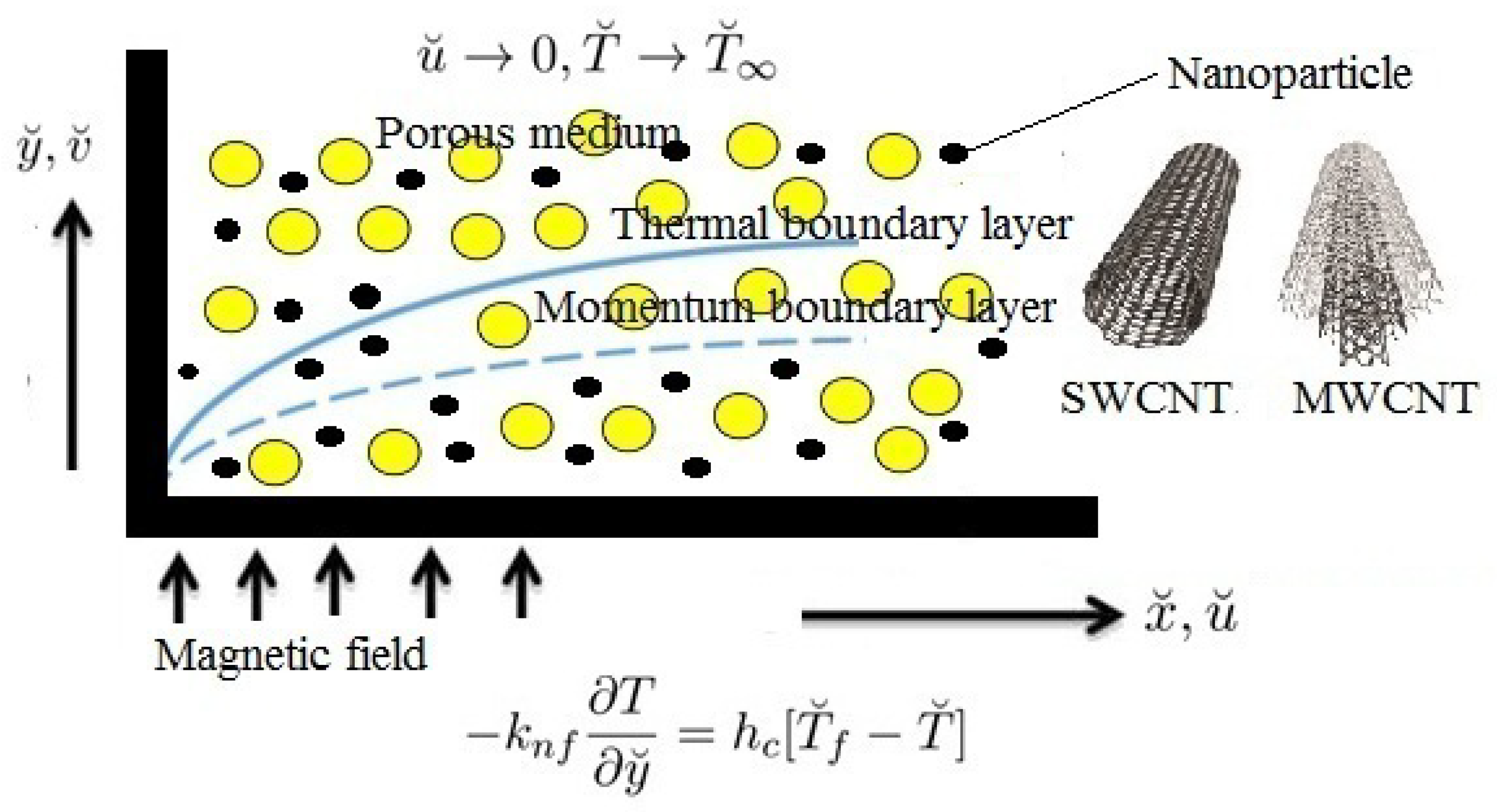
This research aims to simulate the mixed convective flow of CNTs past a stretching plate inserted in a porous medium.
The innovation of the present exploration is:
To investigate the MHD flow over a stretchy plate inserted in a porous medium.
The impacts of Joule heating, viscous dissipation and radiation are also added to the heat expression.
These types of modeled problems are used in the thermal industry for designing equipment, such as the design of electric ovens, electric heaters, microelectronics, wind generators, etc.
4. Results and Discussion
The main objective of this segment is to show how the different pertinent flow parameters affect the fluctuations in the fluid velocity, fluid temperature, skin friction coefficient, and local Nusselt number for SWCNTs, MWCNTs and
nanofluid. The physical properties of SWCNTs, MWCNTs,
and water are presented in
Table 1.
Table 2,
Table 3 and
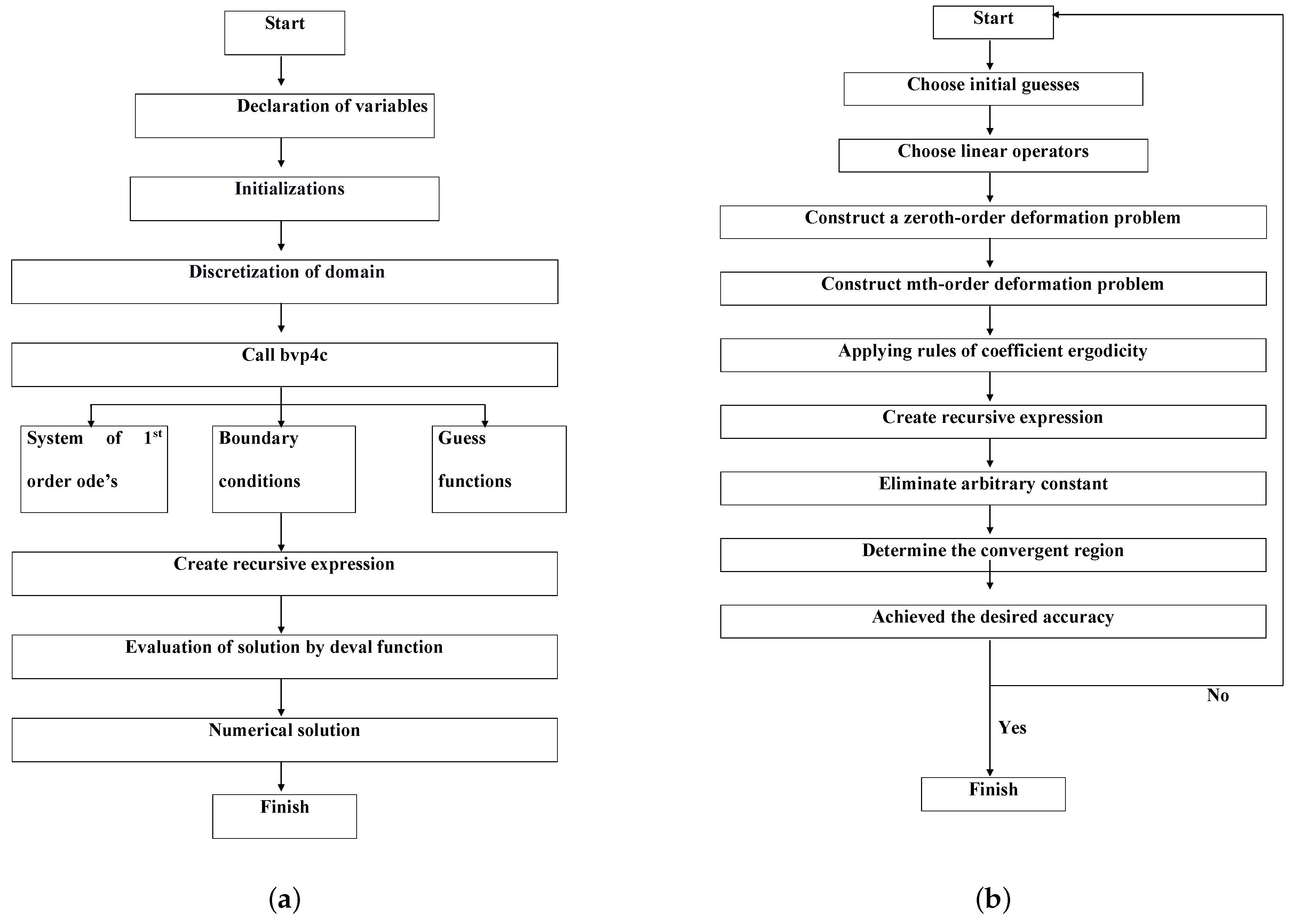
Table 4 clearly display the HAM order of approximations and numerical value for all cases. It can be noted from these tables that the 18th order is sufficient for all computations in all cases. The SFC for various values of
A,
M,
,
,
,
,
and
is shown in
Table 5. This table plainly demonstrates that the plate surface drag force decreases when increasing the size of
A,
M,
and
. On the other hand, during development, it enhances the quantity of
,
,
and
. In addition, MWCNTs have more surface drag force than the SWCNTs and
nanofluid.
Table 6 shows the consequences of
A,
M,
,
,
,
,
and
on LNN. It can be observed from this table that the HTG grows at growing the quantity of
A,
,
,
. However, it diminishes when the values of
M,
,
and
are magnified. Additionally, the SWCNTs have less HTG than the MWCNTs and
nanofluid.
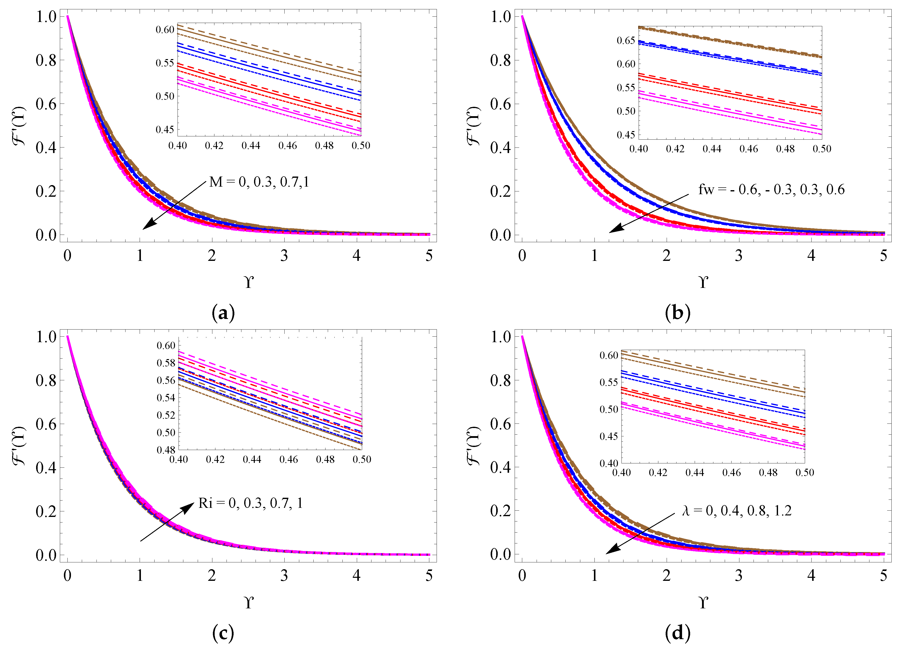
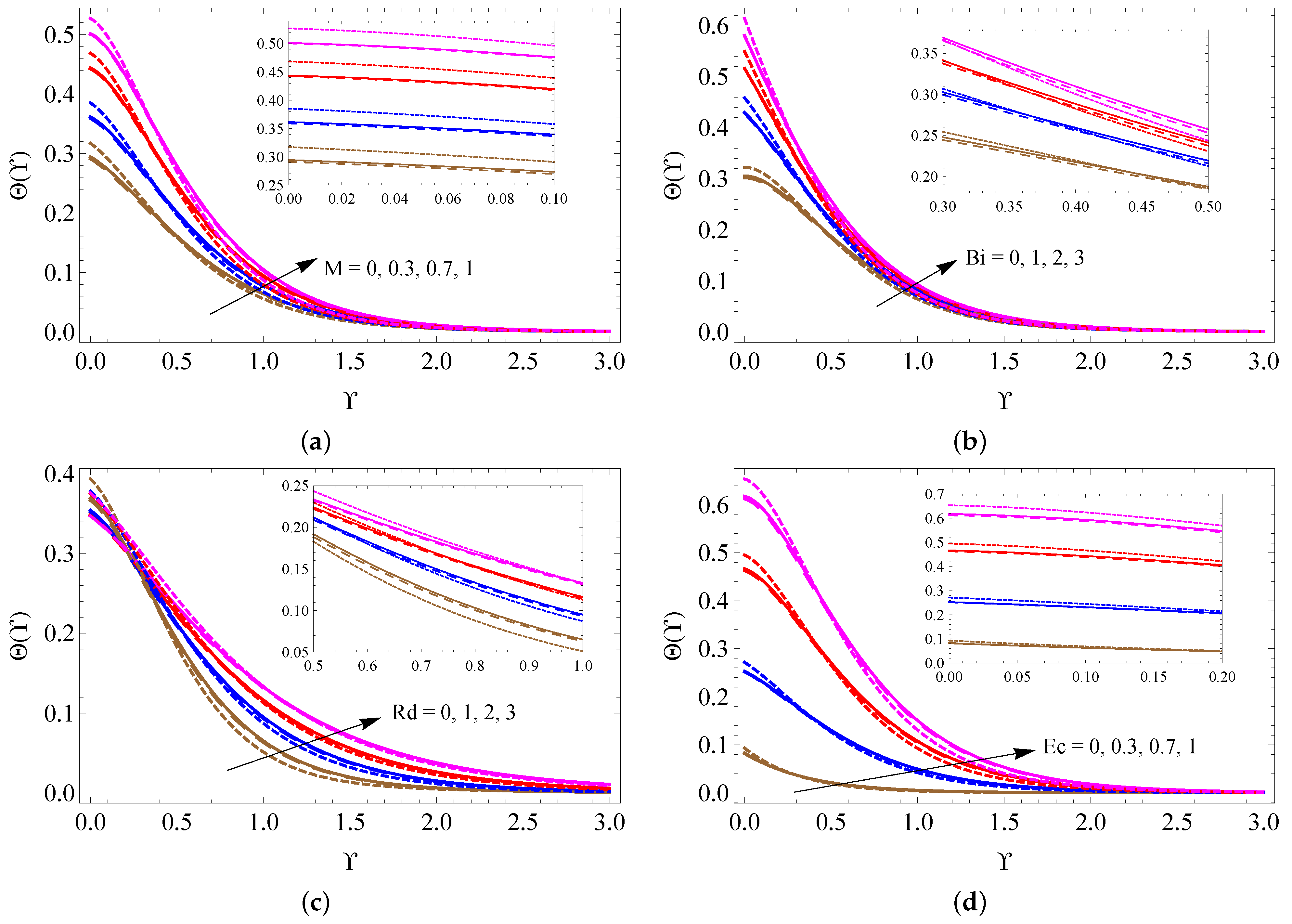
Figure 4a–d is drawn to examine the alterations of
M,
,
and
on the fluid velocity distribution. It is detected from these figures that the larger measure of
improves the fluid motion inside the boundary. On the contrary, the larger size of
M,
and
reduces the fluid motion. The changes in fluid temperature for distinct quantities of
M,
,
and
are pictured in
Figure 5a–d. These figures noticeably point out that the fluid temperature increases when the values of
M,
,
and
increase.
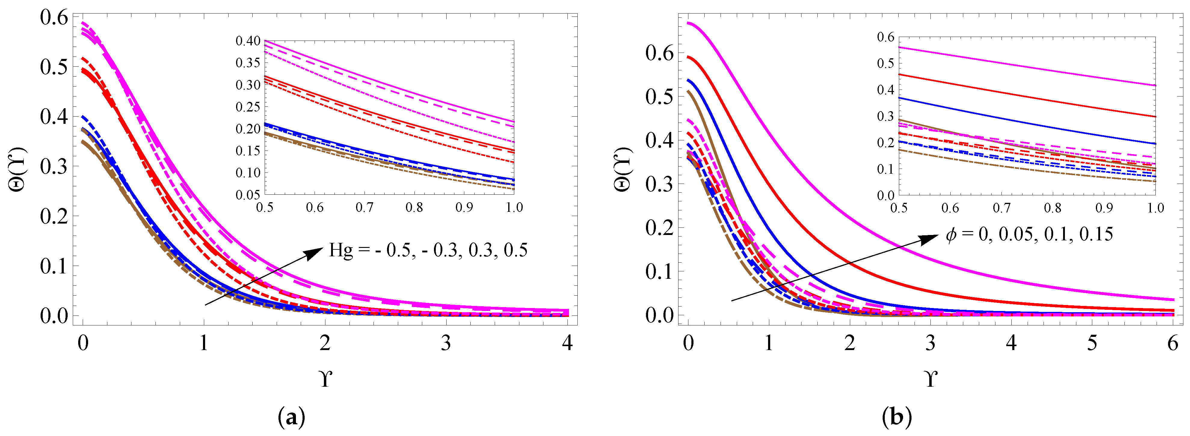
Figure 6a,b is taken to analyze the change of
and
on fluid temperature distribution. It is found from these figures that the fluid temperature escalates when raising the values of
and
.
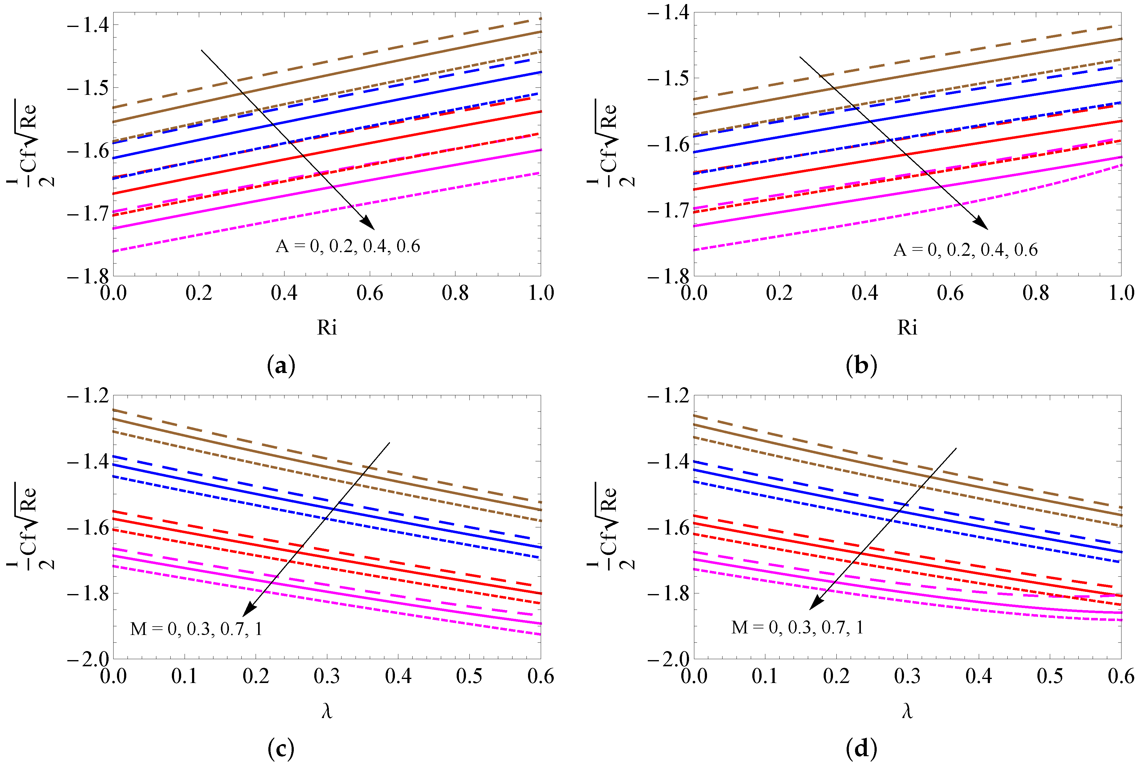
The contrast of the skin friction coefficient for different combinations of
A and
(a–b) and
M and
(c–d) with convective heating (a,c) and convective cooling (b,d) cases are illustrated in
Figure 7a–d. A large amount of unsteady magnetic field and porosity parameters is perceived to lead to a fall out of the SFC. However, it improves when developing the Richardson number for both cases.
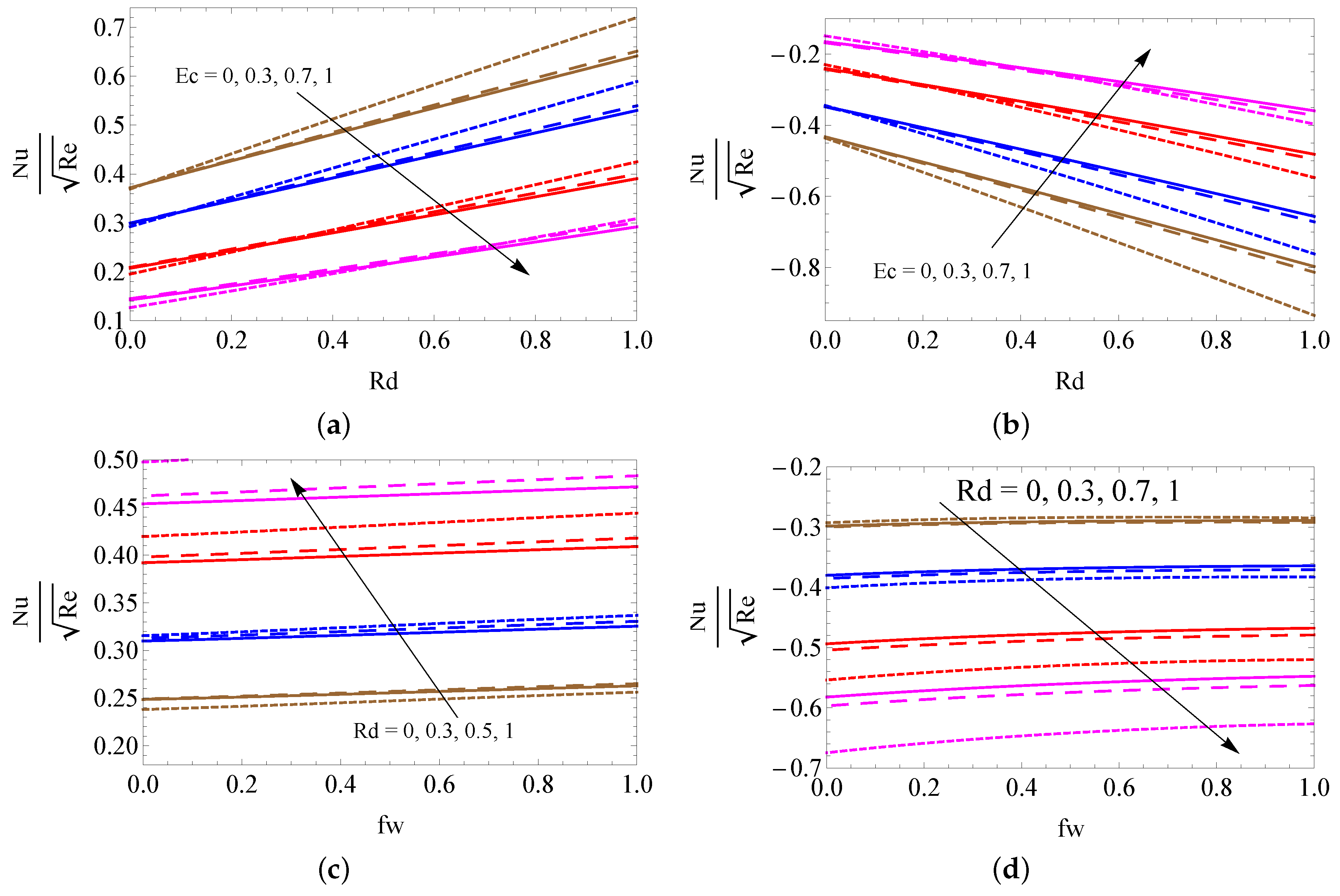
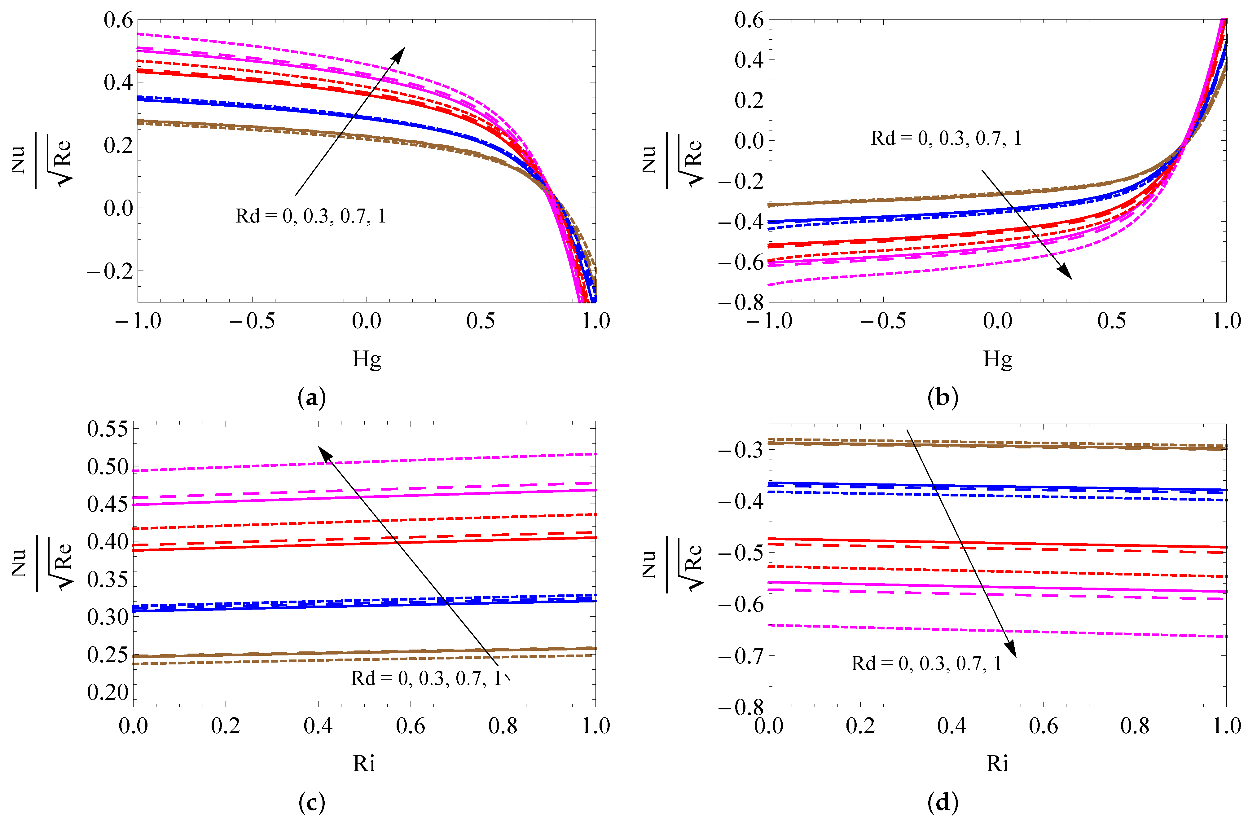
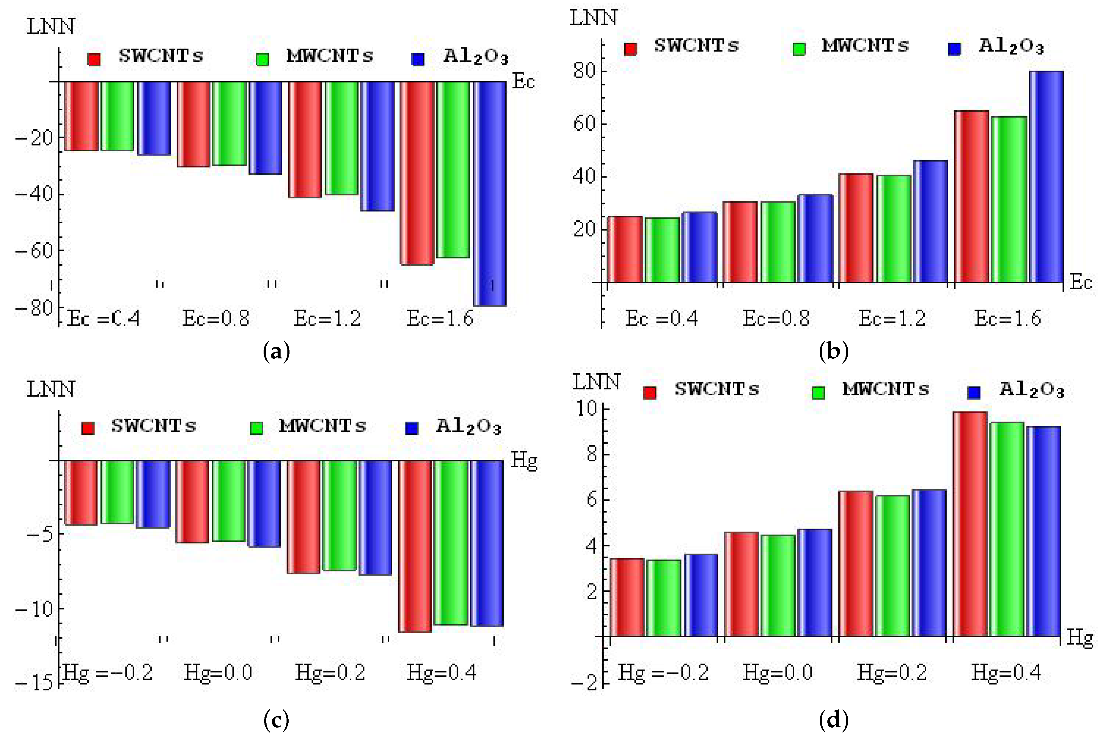
Figure 8a–d is to used to discuss the contrast of LNN for different combinations of
and
(a–b) and
and
(c–d) with convective heating (a,c) and convective cooling (b,d) cases. It is detected from these figures that the larger magnitudes of
and
upsurge the heat transfer gradient, and the Eckert number weakens the LNN for the convective heating case. However, the opposite trend was attained in the convective cooling case. The contrast of LNN for different combinations of
and
(a–b) and
and
(c–d) with convective heating (a,c) and convective cooling (b,d) cases was presented in
Figure 9a–d. It is seen from the graphical overview that the LNN grows when mounting the values of the radiation parameter and Richardson number, and it slumps when enhancing the heat consumption/generation parameter in the convective heating case. The reverse trend is obtained in the convective cooling case.
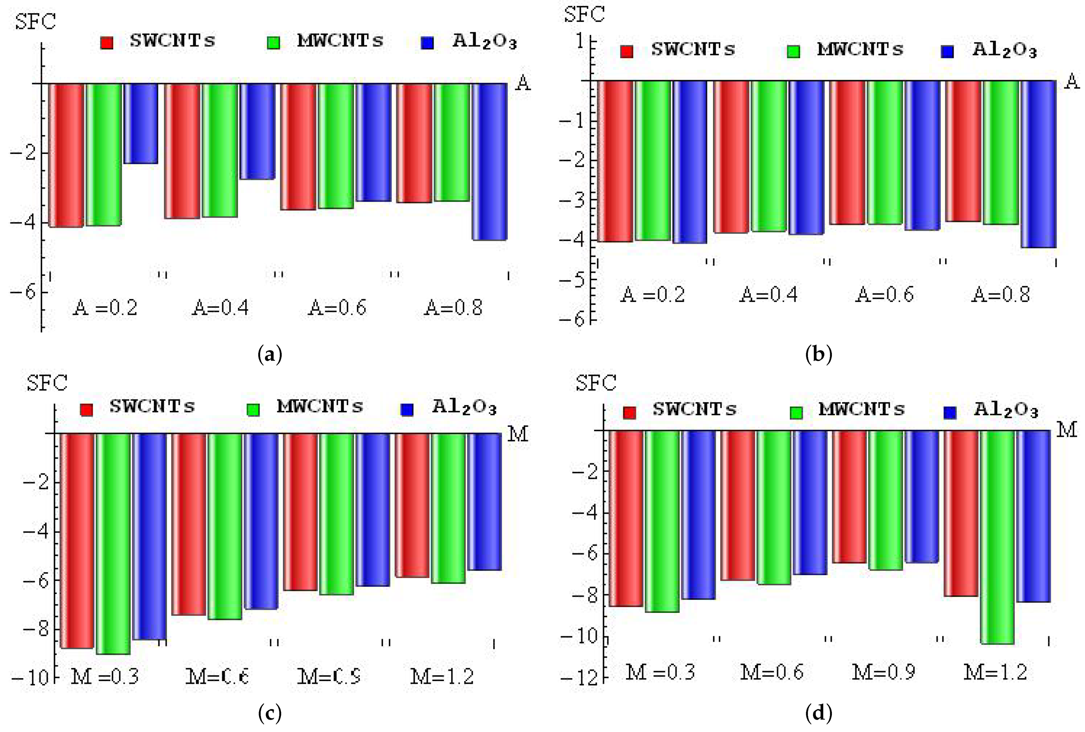
The diminishing percentages of SFC for
A (a–b) and
M (c–d) with convective heating (a,c) and convective cooling (b,d) for SWCNTs, MWCNTs and
nanofluid are drawn in
Figure 10a–d. For the convective heating case, the maximum diminishing percentage
occurred in
nanofluid when changing
A from 0 to
, and the minimum diminishing percentage
appeared in MWCNTs when changing
A from
to
, see
Figure 10a. In the convective cooling case, the maximum diminishing percentage
occurred in
nanofluid when changing
A from
to
, and the minimum diminishing percentage
appeared in SWCNTs when changing
A from
to
(see
Figure 10b). For the convective heating case, the maximum diminishing percentage
occurred in MWCNTs when changing
M from 0 to
, and the minimum diminishing percentage
appeared in
nanofluid when changing
M from
to
(see
Figure 10c). In the convective cooling case, the maximum diminishing percentage
occurred in MWCNTs when changing
M from
to
, and the minimum diminishing percentage
appeared in
nanofluid when changing
M from
to
(see
Figure 10d).
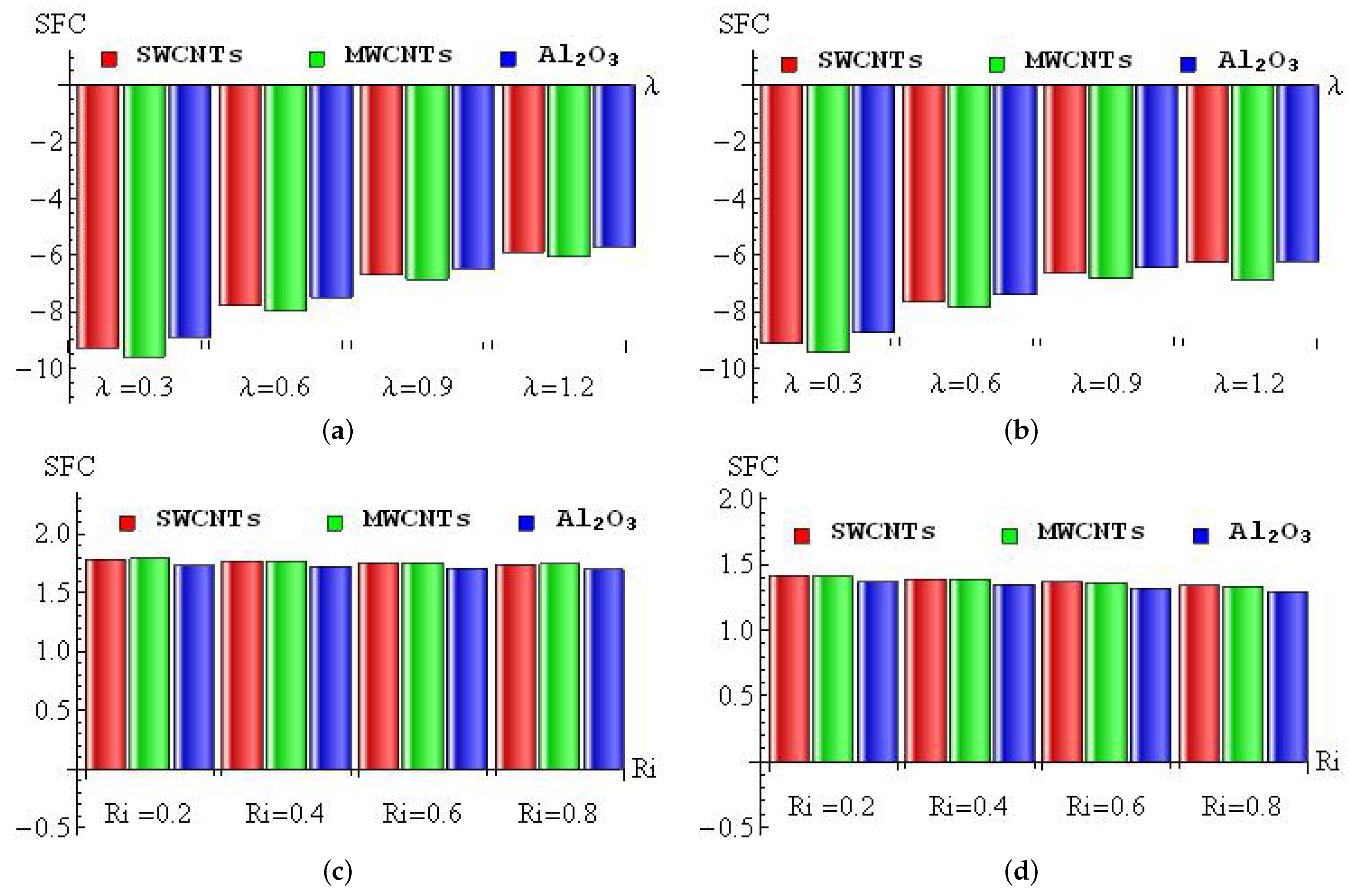
Figure 11a–d is plotted to discuss the diminishing/improving percentage of SFC for
(a–b) and
(c–d) with convective heating (a,c) and convective cooling (b,d) for SWCNTs, MWCNTs and
nanofluid. For the convective heating case, the maximum diminishing percentage
occurred in MWCNTs when changing
from 0 to
, and the minimum diminishing percentage
appeared in
nanofluid when changing
from
to
(see
Figure 11a). In the convective cooling case, the maximum diminishing percentage
occurred in MWCNTs when changing
from 0 to
, and the minimum diminishing percentage
appeared in
nanofluid when changing
from
to
(see
Figure 11b). For the convective heating case, the maximum improving percentage
occurred in MWCNTs when changing
from 0 to
, and the minimum improving percentage
appeared in
nanofluid when changing
from
to
(see
Figure 11c). In the convective cooling case, the maximum improving percentage
occurred in SWCNTs when changing
from 0 to
, and the minimum improving percentage
appeared in
nanofluid when changing
from
to
(see
Figure 11d).
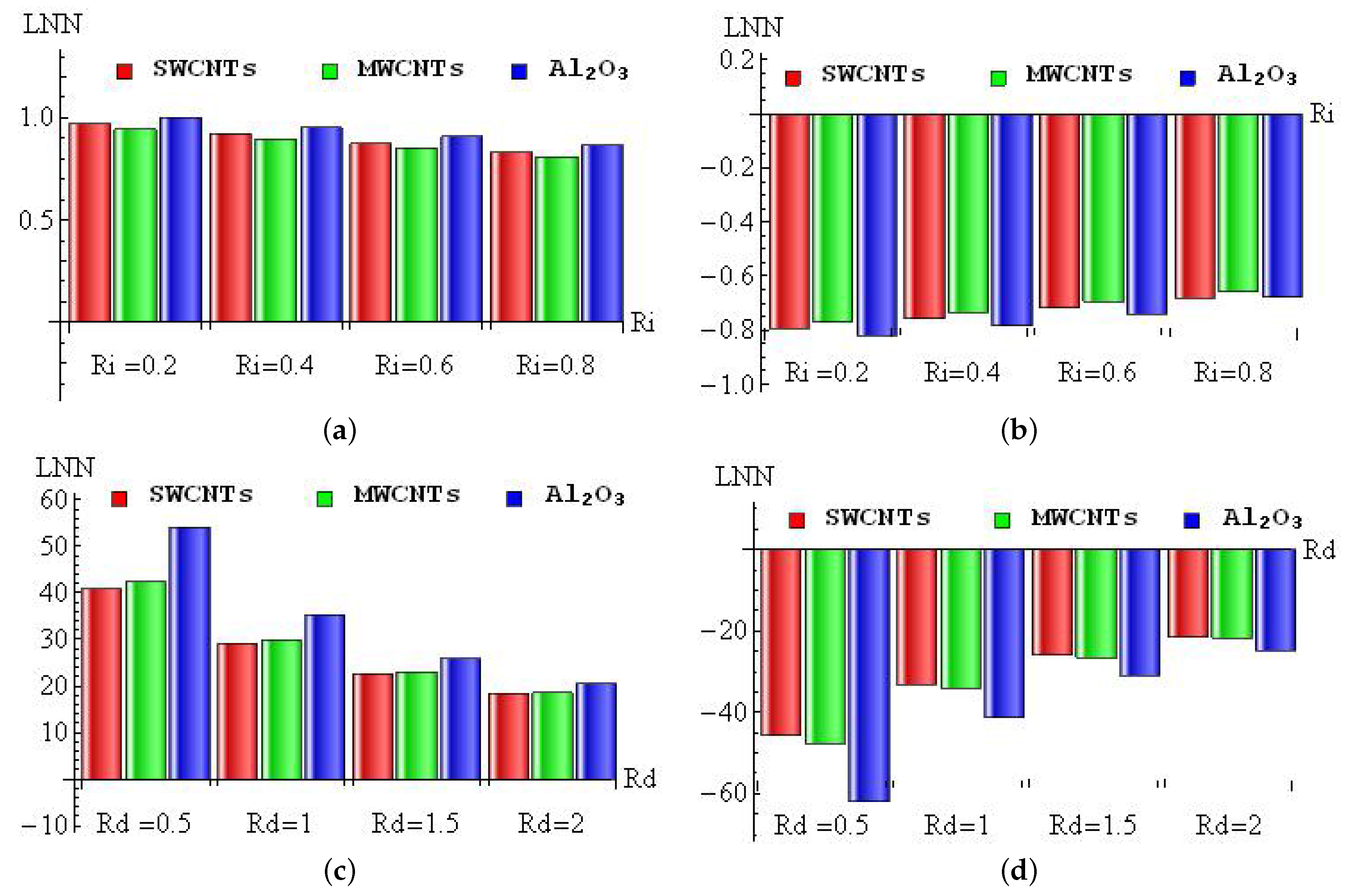
The diminishing/improving percentage of LNN for
(a–b) and
(c–d) with convective heating (a,c) and convective cooling (b,d) for SWCNTs, MWCNTs and
nanofluid are sketched in
Figure 12a–d. For the convective heating case, the maximum improving percentage
occurred in
nanofluid when changing
from 0 to
, and the minimum improving percentage
appeared in MWCNTs when changing
from
to
(see
Figure 12a). In the convective cooling case, the maximum diminishing percentage
occurred in
nanofluid when changing
from 0 to
, and the minimum diminishing percentage
appeared in MWCNTs when changing
from
to
(see
Figure 12b). For the convective heating case, the maximum improving percentage
occurred in
nanofluid when changing
from 0 to
, and the minimum improving percentage
appeared in SWCNTs when changing
from
to 2 (see
Figure 12c). In the convective cooling case, the maximum diminishing percentage
occurred in
nanofluid when changing
from 0 to
, and the minimum diminishing percentage
appeared in SWCNTs when changing
from
to 2 (see
Figure 12d).
Figure 13a–d is taken to examine the diminishing/improving percentage of LNN for
(a–b) and
(c–d) with convective heating (a,c) and convective cooling (b,d) for SWCNTs, MWCNTs and
nanofluid. For the convective heating case, the maximum diminishing percentage
occurred in
nanofluid when changing
from
to
, and the minimum diminishing percentage
appeared in MWCNTs when changing
from 0 to
(see
Figure 13a). In the convective cooling case, the maximum improving percentage
occurred in
nanofluid when changing
from
to
, and the minimum improving percentage
appeared in MWCNTs when changing
from 0 to
(see
Figure 13b). For the convective heating case, the maximum diminishing percentage
occurred in SWCNTs when changing
from
to
, and the minimum diminishing percentage
appeared in MWCNTs when changing
from
to
(see
Figure 13c). In the convective cooling case, the maximum improving percentage
occurred in SWCNTs when changing
from
to
, and the minimum improving percentage
appeared in MWCNTs when changing
from
to
(see
Figure 13d).


