
Recent Progress in Development and Applications of Ionic Polymer–Metal Composite

 , , , and
Abstract
:1. Introduction
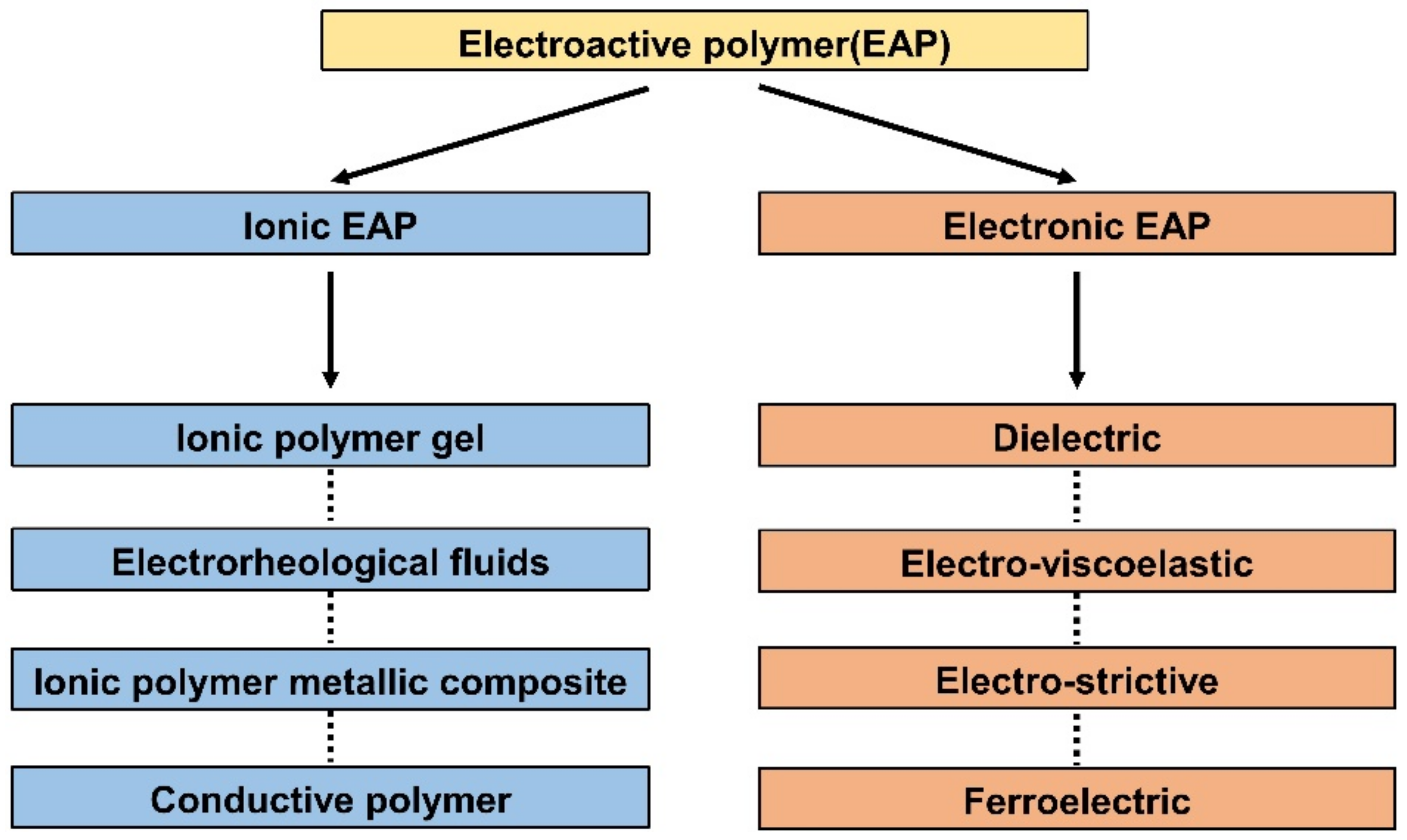
2. Classification of EAP
2.1. Electronic Electroactive Polymer
2.2. Ionic Electroactive Polymer
3. Classification of Ionic EAP
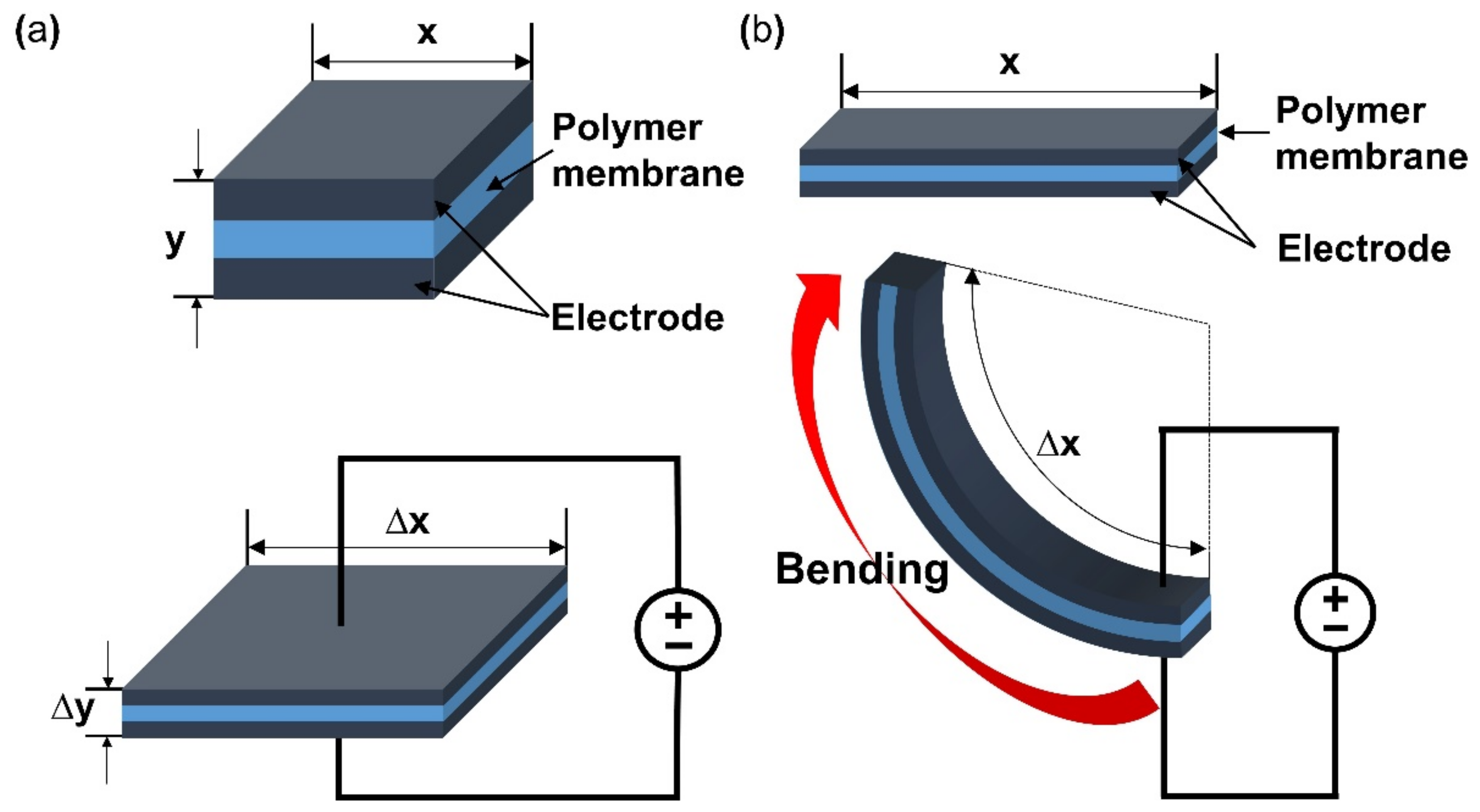
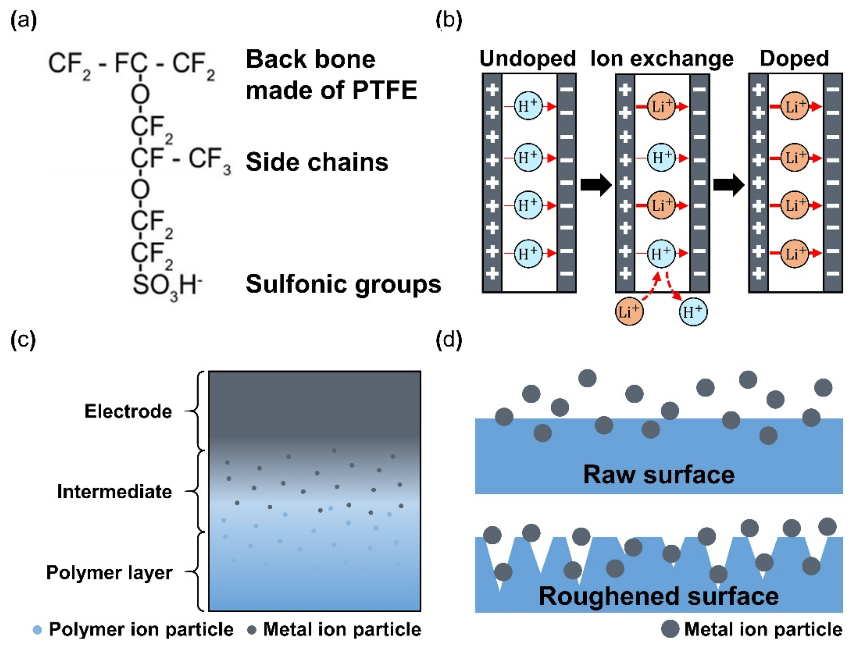
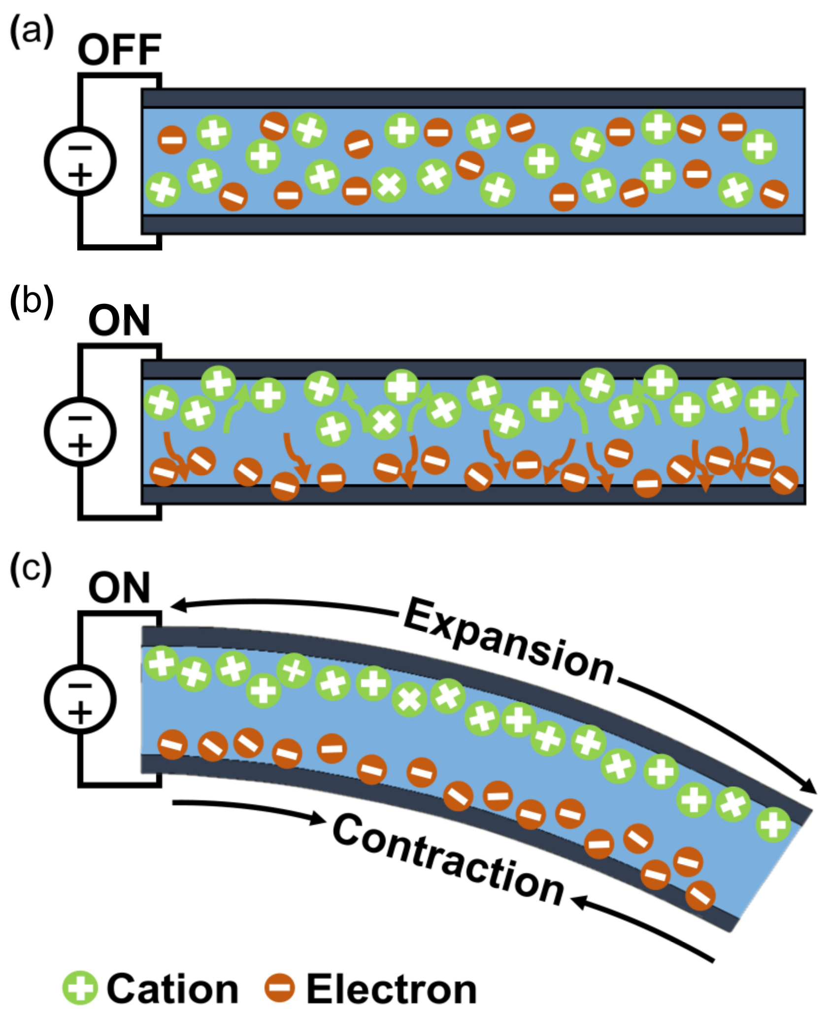
3.1. Ionic Polymer–Metal Composite
3.2. Other Types of Ionic EAP
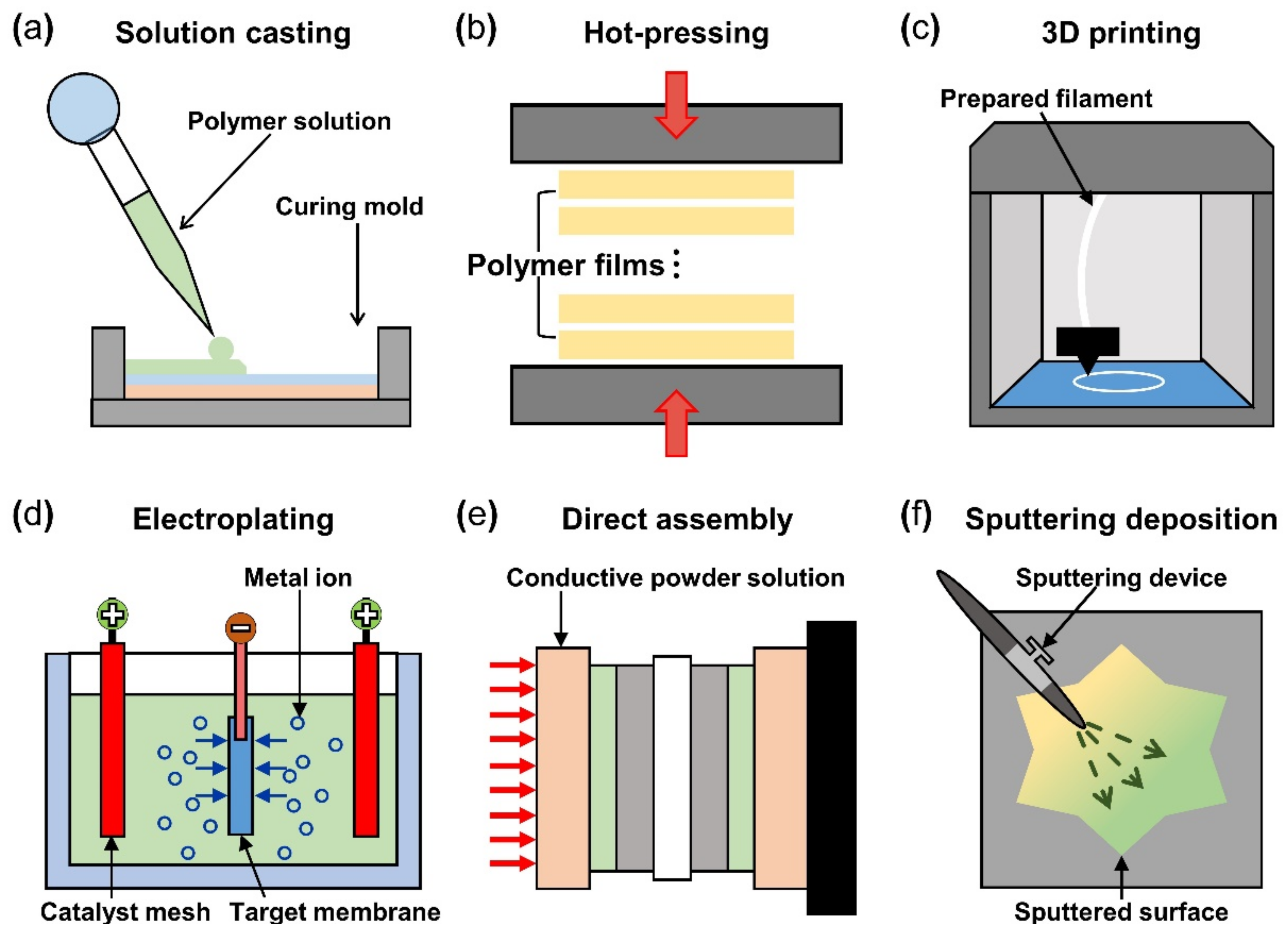
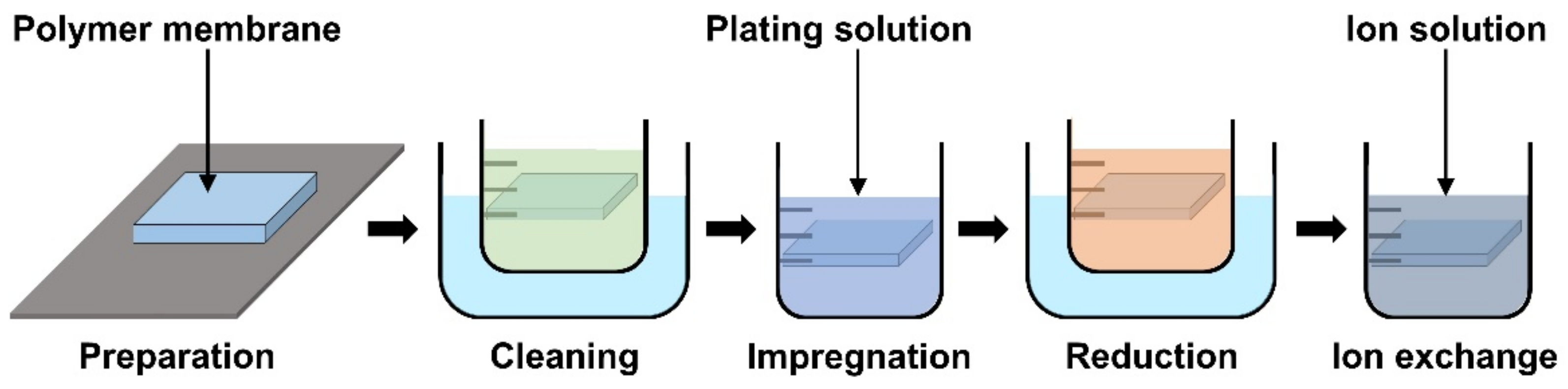
4. Materials and Fabrication of IPMC
4.1. Materials and Fabrication of Polymer Membrane
4.2. Materials and Fabrication of Electrode
5. Application of IPMC
5.1. Actuator
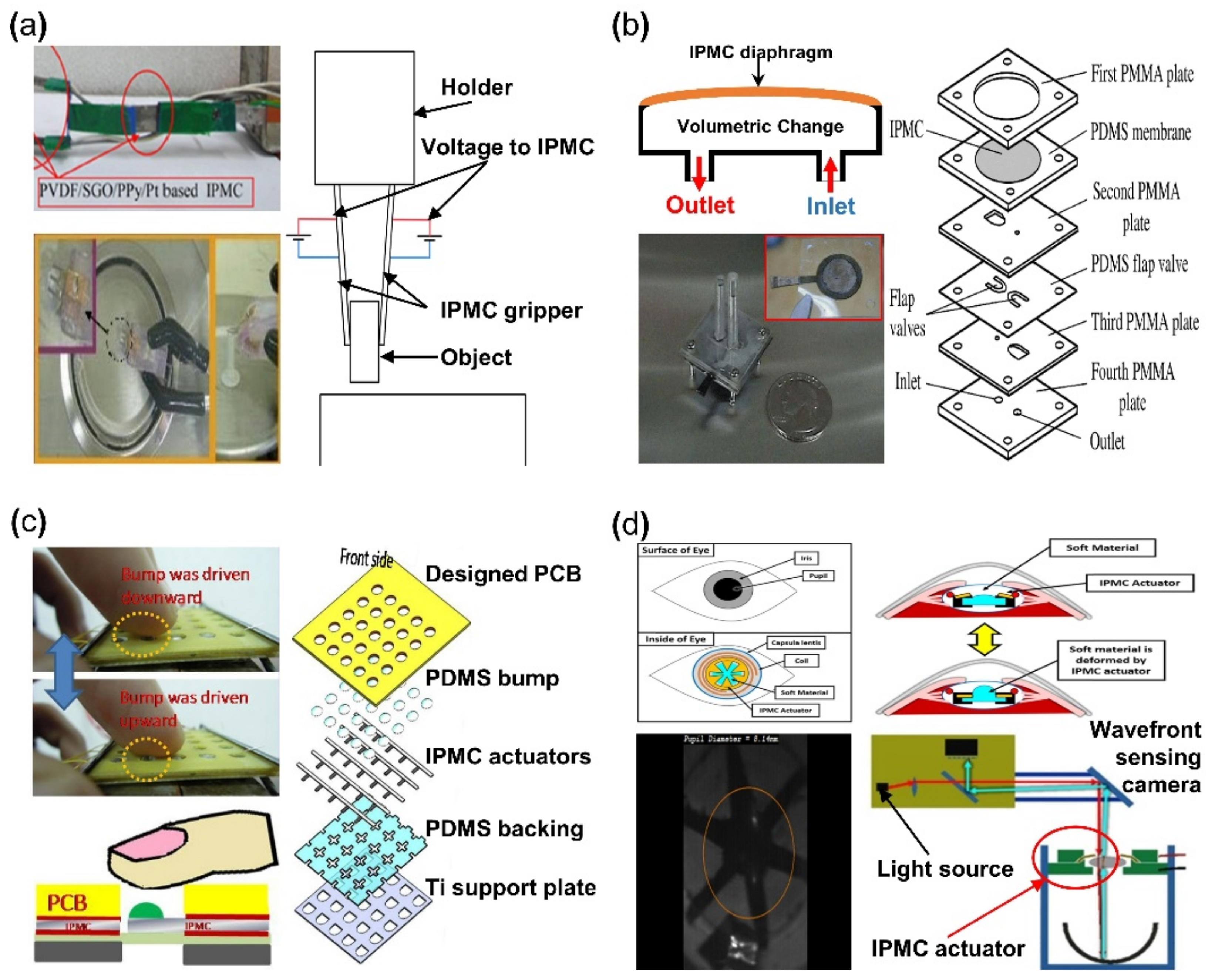
5.1.1. Gripper
5.1.2. Micro-Pump
5.1.3. Biomedical
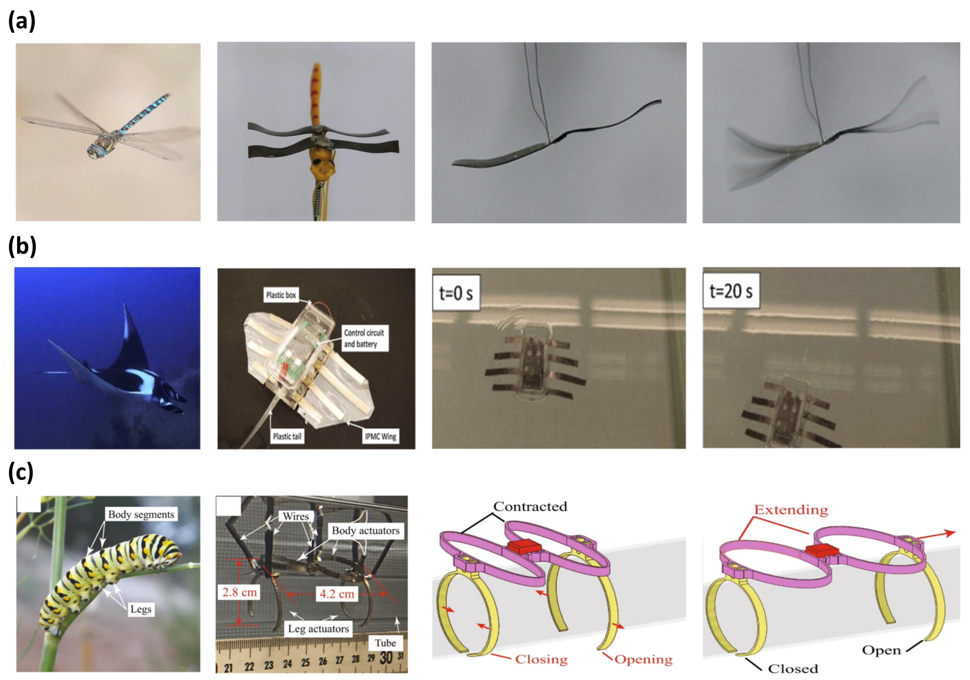
5.1.4. Biomimetic Application
5.2. Sensor
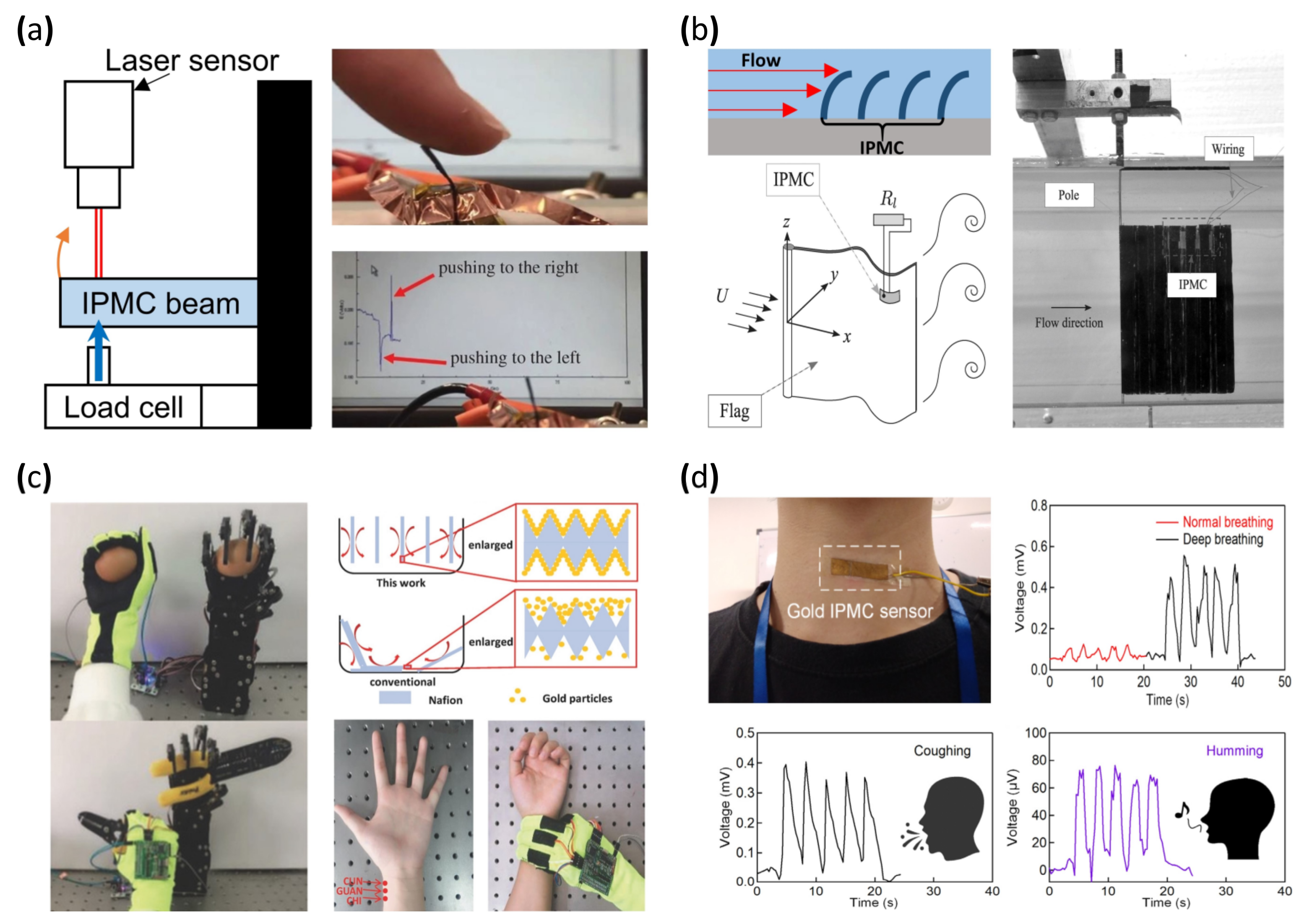
5.2.1. Bending and Displacement Sensor
5.2.2. Flow Sensor
5.2.3. Energy Harvesting
5.2.4. Biosensor
5.2.5. Humidity Sensor
6. Conclusions
Author Contributions
Funding
Data Availability Statement
Conflicts of Interest
References
- Wei, M.; Gao, Y.; Li, X.; Serpe, M.J. Stimuli-responsive polymers and their applications. Polym. Chem. 2017, 8, 127–143. [Google Scholar] [CrossRef]
- Yang, Y.; Tse, Y.A.; Zhang, Y.; Kan, Z.; Wang, M.Y. A Low-cost Inchworm-inspired Soft Robot Driven by Supercoiled Polymer Artificial Muscle. In Proceedings of the 2nd IEEE International Conference on Soft Robotics (RoboSoft), Seoul, Korea, 14–18 April 2019; pp. 161–166. [Google Scholar]
- Agostini, M.; Hassoun, J. A lithium-ion sulfur battery using a polymer, polysulfide-added membrane. Sci. Rep. 2015, 5, 7591. [Google Scholar] [CrossRef] [PubMed]
- Hammes, P.C.A.; Regtien, P.P.L. An integrated infrared sensor using the pyroelectric polymer PVDF. Sens. Actuator A Phys. 1992, 32, 396–402. [Google Scholar] [CrossRef]
- Stansbury, J.W.; Idacavage, M.J. 3D printing with polymers: Challenges among expanding options and opportunities. Dent. Mater. J. 2016, 32, 54–64. [Google Scholar]
- Engel, K.E.; Kilmartin, P.A.; Diegel, O. Recent advances in the 3D printing of ionic electroactive polymers and core ionomeric materials. Polym. Chem. 2022, 13, 456–473. [Google Scholar] [CrossRef]
- Wang, G.J.; Molina-Lopez, F.; Zhang, H.; Xu, J.; Wu, H.-C.; Lopez, J.; Shaw, L.; Mun, J.; Zhang, Q.; Wang, S.; et al. Nonhalogenated Solvent Procesable and Printable High-Performance Polymer Semiconductor Enabled by Isomeric Nonconjugated Flexible Linkers. Macromolecules 2018, 51, 4976–4985. [Google Scholar] [CrossRef]
- Pavase, T.R.; Lin, H.; Shaikh, Q.-u.-a.; Hussain, S.; Li, Z.; Ahmed, I.; Lv, L.; Sun, L.; Shah, S.B.H.; Kalhoro, M.T. Recent advances of conjugated polymer (CP) nanocomposite-based chemical sensors and their aplications in food spoilage detection: A comprehensive review. Sens. Actuators B Chem. 2018, 273, 1113–1138. [Google Scholar]
- Manouras, T.; Vamvakaki, M. Field responsive materials: Photo-, electro-, magnetic- and ultrasound-sensitive polymers. Polym. Chem. 2017, 8, 74–96. [Google Scholar] [CrossRef]
- Jochum, F.D.; Theato, P. Temperature- and light-responsive smart polymer materials. Chem. Soc. Rev. 2013, 42, 7468–7483. [Google Scholar] [CrossRef]
- Kotsuchibashi, Y. Recent advances in multi-temperature-responsive polymeric materials. Polym. J. 2020, 52, 681–689. [Google Scholar] [CrossRef]
- Bashir, M.; Rajendran, P. A review on electroactive polymers development for aerospace applications. J. Intell. Mater. Syst. Struct. 2018, 29, 3681–3695. [Google Scholar] [CrossRef]
- Bar-Choen, Y. EAP as artificial muscles: Progress and challenges. In Proceedings of the Smart Structures and Materials 2004 Conference, San Diego, CA, USA, 15–18 March 2004; pp. 10–16. [Google Scholar]
- De Rossi, D.; Carpi, F.; Galantini, F. Functional Materials for Wearable Sensing, Actuating and Energy Harvesting. In Proceedings of the 3rd International Conference on Smart Materials, Structures and Systems, Acireale, Italy, 8–13 June 2008; pp. 247–256. [Google Scholar]
- Pohanka, M. The Piezoelectric Biosensors: Principles and Applications, a Review. Int. J. Electrochem. Sci. 2017, 12, 496–506. [Google Scholar] [CrossRef]
- Rahman, M.H.; Werth, H.; Goldman, A.; Hida, Y.; Diesner, C.; Lane, L.; Menezes, P.L. Recent Progress on Electroactive Polymers: Synthesis, Properties and Applications. Ceramics 2021, 4, 516–541. [Google Scholar] [CrossRef]
- Bar-Cohen, Y.; Anderson, I.A. Electroactive polymer (EAP) actuators—background review. Mech. Soft Mater. 2019, 1, 5. [Google Scholar] [CrossRef]
- Youn, J.-H.; Jeong, S.M.; Hwang, G.; Kim, H.; Hyeon, K.; Park, J.; Kyung, K.-U. Dielectric Elastomer Actuator for Soft Robotics Applications and Challenges. Appl. Sci. 2020, 10, 640. [Google Scholar] [CrossRef]
- Duduta, M.; Hajiesmaili, E.; Zhao, H.; Wood, R.J.; Clarke, D.R. Realizing the potential of dielectric elastomer artificial muscles. Proc. Natl. Acad. Sci. USA 2019, 116, 2476–2481. [Google Scholar] [CrossRef]
- Kovacs, G.; Düring, L. Contractive tension force stack actuator based on soft dielectric EAP. In Proceedings of the Smart Structures and Materials 2009: Electroactive Polymer Actuators and Devices (EAPAD), San Diego, CA, USA, 6 March 2009; p. 72870A. [Google Scholar]
- Qian, X.; Wu, S.; Furman, E.; Zhang, Q.M.; Su, J. Ferroelectric polymers as multifunctional electroactive materials: Recent advances, potential, and challenges. MRS Commun. 2015, 5, 115–129. [Google Scholar] [CrossRef]
- Cottinet, P.-J.; Guyomar, D.; Guiffard, B.; Lebrun, L.; Putson, C. Electrostrictive polymer composite for energy harvesters and actuators. J. Polym. Eng. 2011, 31, 133–140. [Google Scholar] [CrossRef]
- Bar-Cohen, Y. Electroactive polymers as artificial muscles—Reality and challenges. In Proceedings of the 19th AIAA Applied Aerodynamics Conference, Anaheim, CA, USA, 11–14 June 2001; p. 1492. [Google Scholar]
- Bar-Cohen, Y. Artificial Muscles Using Electroactive Polymers (EAP): Capabilities, Challenges and Potential; Jet Propulsion Laboratory, National Aeronautics and Space Administration: Pasadena, CA, USA, 2005. [Google Scholar]
- Romasanta, L.J.; López-Manchado, M.A.; Verdejo, R. Increasing the performance of dielectric elastomer actuators: A review from the materials perspective. Prog. Polym. Sci. 2015, 51, 188–211. [Google Scholar] [CrossRef]
- Srivastava, S. Specialty polymers: Exploring versatility in types, applications and future prospects. Int. J. Recent Sci. Res. 2017, 8, 20142–20149. [Google Scholar]
- Shahinpoor, M. Fundamentals of Ionic Polymer Metal Composites (IPMCs). In Ionic Polymer Metal Composites (IPMCs): Smart Multi-Functional Materials and Artificial Muscles, Volume 1; The Royal Society of Chemistry: London, UK, 2016; Volume 1, pp. 1–60. [Google Scholar]
- Shahinpoor, M. Mechanoelectrical phenomena in ionic polymers. Math Mech Solids 2003, 8, 281–288. [Google Scholar] [CrossRef]
- Hao, M.; Wang, Y.; Zhu, Z.; He, Q.; Zhu, D.; Luo, M. A Compact Review of IPMC as Soft Actuator and Sensor: Current Trends, Challenges, and Potential Solutions From Our Recent Work. Front. Robot. AI 2019, 6, 129. [Google Scholar] [CrossRef] [PubMed]
- Ma, S.; Zhang, Y.; Liang, Y.; Ren, L.; Tian, W.; Ren, L. High-Performance Ionic-Polymer–Metal Composite: Toward Large-Deformation Fast-Response Artificial Muscles. Adv. Funct. Mater. 2020, 30, 1908508. [Google Scholar] [CrossRef]
- Uh, K.; Yoon, B.; Lee, C.W.; Kim, J.-M. An Electrolyte-Free Conducting Polymer Actuator that Displays Electrothermal Bending and Flapping Wing Motions under a Magnetic Field. ACS Appl. Mater. Interfaces 2016, 8, 1289–1296. [Google Scholar] [CrossRef] [PubMed]
- Miyoshi, T.; Yoshida, K.; Kim, J.-w.; Eom, S.I.; Yokota, S. An MEMS-based multiple electro-rheological bending actuator system with an alternating pressure source. Sens. Actuator A Phys. 2016, 245, 68–75. [Google Scholar] [CrossRef]
- Punning, A.; Kruusmaa, M.; Aabloo, A. Aabloo, A.; A self-sensing ion conducting polymer metal composite (IPMC) actuator. Sens. Actuator A Phys. 2007, 136, 656–664. [Google Scholar] [CrossRef]
- Biddiss, E.; Chau, T. Electroactive polymeric sensors in hand prostheses: Bending response of an ionic polymer metal composite. Med. Eng. Phys. 2006, 28, 568–578. [Google Scholar] [CrossRef]
- Stenger-Smith, J.D.; Lai, W.W.; Irvin, D.J.; Yandek, G.R.; Irvin, J.A. Electroactive polymer-based electrochemical capacitors using poly(benzimidazo-benzophenanthroline) and its pyridine derivative poly(4-aza-benzimidazo-benzophenanthroline) as cathode materials with ionic liquid electrolyte. J. Power Sources 2012, 220, 236–242. [Google Scholar] [CrossRef]
- Shen, Q.; Trabia, S.; Stalbaum, T.; Palmre, V.; Kim, K.; Oh, I.K. A multiple-shape memory polymer-metal composite actuator capable of programmable control, creating complex 3D motion of bending, twisting, and oscillation. Sci. Rep. 2016, 6, 24462. [Google Scholar] [CrossRef]
- Liang, W.; Liu, H.; Wang, K.; Qian, Z.; Ren, L.; Ren, L. Comparative study of robotic artificial actuators and biological muscle. Adv. Mech. Eng. 2020, 12, 1687814020933409. [Google Scholar] [CrossRef]
- Guo, D.; Wang, L.; Wang, X.; Xiao, Y.; Wang, C.; Chen, L.; Ding, Y. PEDOT coating enhanced electromechanical performances and prolonged stable working time of IPMC actuator. Sens. Actuators B Chem. 2020, 305, 127488. [Google Scholar] [CrossRef]
- Neuhaus, R.; Zahiri, N.; Petrs, J.; Tahouni, Y.; Siegert, J.; Kolaric, I.; Dahy, H.; Bauernhansl, T. Integrating Ionic Electroactive Polymer Actuators and Sensors Into Adaptive Building Skins—Potentials and Limitations. Front. Built Environ. 2020, 6, 2297–3362. [Google Scholar] [CrossRef]
- Lei, H.; Li, W.; Tan, X. Encapsulation of ionic polymer-metal composite (IPMC) sensors with thick parylene: Fabrication process and characterization results. Sens. Actuator A Phys. 2014, 217, 1–12. [Google Scholar] [CrossRef]
- Song, D.S.; Han, D.G.; Rhee, K.; Kim, D.M.; Jho, J.Y. Fabrication and characterization of an ionic polymer-metal composite bending sensor. Macromol. Res. 2017, 25, 1205–1211. [Google Scholar] [CrossRef]
- Kim, M.J.; Park, S.W.; Won, J.; Nah, C. Effects of ionic liquids on the performance of IPMC. EAPAD 2017, 10163, 602–605. [Google Scholar]
- Lee, J.-W.; Yoo, Y.-T. Anion effects in imidazolium ionic liquids on the performance of IPMCs. Sens. Actuators B Chem. 2009, 137, 539–546. [Google Scholar] [CrossRef]
- Safari, M.; Naji, L.; Baker, R.T.; Taromi, F.A. The enhancement effect of lithium ions on actuation performance of ionic liquid-based IPMC soft actuators. Polymers 2015, 76, 140–149. [Google Scholar] [CrossRef]
- Yuk, H.; Lu, B.; Lin, S.; Qu, K.; Xu, J.; Luo, J.; Zhao, X. 3D printing of conducting polymers. Nat. Commun. 2020, 11, 1604. [Google Scholar] [CrossRef]
- Palleau, E.; Morales, D.; Dickey, M.D.; Velev, O.D. Reversible patterning and actuation of hydrogels by electrically assisted ionoprinting. Nat. Commun. 2013, 4, 2257. [Google Scholar] [CrossRef]
- Mazursky, A.; Koo, J.-H.; Mason, T.; Woo, S.-Y.; Yang, T.-H. Design and Experimental Evaluation of an Electrorheological Haptic Module with Embedded Sensing. Appl. Sci. 2021, 11, 7723. [Google Scholar] [CrossRef]
- Zhan, C.; Yu, G.; Lu, Y.; Wang, L.; Wujcik, E.; Wei, S. Conductive polymer nanocomposites: A critical review of modern advanced devices. J. Mater. Chem. C 2017, 5, 1569–1585. [Google Scholar] [CrossRef]
- Kumar, D.; Sharma, R. Advances in conductive polymers. Eur. Polym. 1998, 34, 1053–1060. [Google Scholar] [CrossRef]
- Kayser, L.V.; Lipomi, D.J. Stretchable Conductive Polymers and Composites Based on PEDOT and PEDOT: PSS. Adv. Mater. 2019, 31, 1806133. [Google Scholar] [CrossRef]
- Tsukada, S.; Nakashima, H.; Torimitsu, K. Conductive Polymer Combined Silk Fiber Bundle for Bioelectrical Signal Recording. PLoS ONE 2012, 7, e33689. [Google Scholar] [CrossRef]
- Chen, J.; Zhu, Y.; Huang, J.; Zhang, J.; Pan, D.; Zhou, J.; Ryu, J.E.; Umar, A.; Guo, Z. Advances in Responsively Conductive Polymer Composites and Sensing Applications. Polym. Rev. 2021, 61, 157–193. [Google Scholar] [CrossRef]
- Zhou, J.; Mulle, M.; Zhang, Y.; Xu, X.; Li, E.Q.; Han, F.; Thoroddsen, S.T.; Lubineau, G. High-ampacity conductive polymer microfibers as fast response wearable heaters and electromechanical actuators. J. Mater. Chem. C 2016, 4, 1238–1249. [Google Scholar] [CrossRef]
- Wang, D.; Zhao, S.; Yin, R.; Li, L.; Lou, Z.; Shen, G. Recent advanced applications of ion-gel in ionic-gated transistor. Npj Flex. Electron. 2021, 5, 13. [Google Scholar] [CrossRef]
- Wang, H.; Wang, Z.; Yang, J.; Xu, C.; Zhang, Q.; Peng, Z. Ionic Gels and Their Applications in Stretchable Electronics. Macromol. Rapid Commun. 2018, 39, 1800246. [Google Scholar] [CrossRef]
- Shiga, T.; Hirose, Y.; Okada, A.; Kurauchi, T. Deformation of ionic polymer gel films in electric fields. J. Mater. Sci. 1994, 29, 5715–5718. [Google Scholar] [CrossRef]
- Fuller, J.; Breda, A.; Carlin, R. Ionic liquid-polymer gel electrolytes. J. Electrochem. Soc. 1997, 144, L67–L70. [Google Scholar] [CrossRef]
- Shahinpoor, M. Conceptual design, kinematics and dynamics of swimming robotic structures using ionic polymeric gel muscles. Smart Mater. Struct. 1992, 1, 91–94. [Google Scholar] [CrossRef]
- Hyun, W.J.; De Moraes, A.C.M.; Lim, J.-M.; Downing, J.R.; Park, K.-Y.; Tan, M.T.Z.; Hersam, M.C. High-Modulus Hexagonal Boron Nitride Nanoplatelet Gel Electrolytes for Solid-State Rechargeable Lithium-Ion Batteries. ACS Nano 2019, 13, 9664–9672. [Google Scholar] [CrossRef] [PubMed]
- Larson, C.; Peele, B.; Li, S.; Robinson, S.; Totaro, M.; Beccai, L.; Mazzolai, B.; Shepherd, R. Highly stretchable electroluminescent skin for optical signaling and tactile sensing. Science 2016, 351, 1071–1074. [Google Scholar] [CrossRef]
- Feng, L.; Wang, K.; Zhang, X.; Sun, X.; Li, C.; Ge, X.; Ma, Y. Flexible Solid-State Supercapacitors with Enhanced Performance from Hierarchically Graphene Nanocomposite Electrodes and Ionic Liquid Incorporated Gel Polymer Electrolyte. Adv. Funct. Mater. 2018, 28, 1704463. [Google Scholar] [CrossRef]
- Mukai, K.; Asaka, K.; Kiyohara, K.; Sugino, T.; Takeuchi, I.; Fukushima, T.; Aida, T. High performance fully plastic actuator based on ionic-liquid-based bucky gel. Electrochim. Acta 2008, 53, 5555–5562. [Google Scholar] [CrossRef]
- Hines, L.; Petersen, K.; Lum, G.Z.; Sitti, M. Soft Actuators for Small-Scale Robotics. Adv. Mater. 2017, 29, 1603483. [Google Scholar] [CrossRef]
- Shao, C.; Wang, M.; Meng, L.; Chang, H.; Wang, B.; Xu, F.; Yang, J.; Wan, P. Mussel-Inspired Cellulose Nanocomposite Tough Hydrogels with Synergistic Self-Healing, Adhesive, and Strain-Sensitive Properties. Chem. Mater. 2018, 30, 3110–3121. [Google Scholar] [CrossRef]
- Hao, T. Electrorheological Fluids. Adv. Mater. 2001, 13, 1847–1857. [Google Scholar] [CrossRef]
- Nguyen, Q.-H.; Choi, S.-B. Dynamic modeling of an electrorheological damper considering the unsteady behavior of electrorheological fluid flow. Smart Mater. Struct. 2009, 18, 055016. [Google Scholar] [CrossRef]
- Li, C.L.; Chen, J.K.; Fan, S.K.; Ko, F.H.; Chang, F.C. Electrorheological operation of low-/high-permittivity core/shell SiO2/Au nanoparticle microspheres for display media. ACS Appl. Mater. Interfaces 2012, 4, 5650–5661. [Google Scholar] [CrossRef]
- Wen, W.; Huang, X.; Yang, S.; Lu, K.; Sheng, P. The giant electrorheological effect in suspensions of nanoparticles. Nat. Mater. 2003, 2, 727–730. [Google Scholar] [CrossRef] [PubMed]
- Yang, L.; Wang, H.; Zhang, X. Recent progress in preparation process of ionic polymer-metal composites. Results Phys. 2021, 29, 104800. [Google Scholar] [CrossRef]
- Mehraeen, S.; Sadeghi, S.; Cebeci, F.Ç.; Papila, M.; Alkan Gürsel, S. Polyvinylidene fluoride grafted poly(styrene sulfonic acid) as ionic polymer-metal composite actuator. Sens. Actuator A Phys. 2018, 279, 157–167. [Google Scholar] [CrossRef]
- Kikuchi, K.; Tsuchitani, S. Nafion®-based polymer actuators with ionic liquids as solvent incorporated at room temperature. J. Appl. Phys. 2009, 106, 053519. [Google Scholar] [CrossRef]
- Panwar, V.; Cha, K.; Park, J.-O.; Park, S. High actuation response of PVDF/PVP/PSSA based ionic polymer metal composites actuator. Sens. Actuators B Chem. 2012, 161, 460–470. [Google Scholar] [CrossRef]
- Lee, J.-W.; Kim, J.-H.; Chun, Y.S.; Yoo, Y.T.; Hong, S.M. The performance of Nafion-based IPMC actuators containing polypyrrole/alumina composite fillers. Macromol. Res. 2009, 17, 1032–1038. [Google Scholar] [CrossRef]
- Nguyen, V.K.; Lee, J.W.; Yoo, Y. Characteristics and performance of ionic polymer–metal composite actuators based on Nafion/layered silicate and Nafion/silica nanocomposites. Sens. Actuators B Chem. 2007, 120, 529–537. [Google Scholar] [CrossRef]
- Yip, J.; Ding, F.; Yick, K.-L.; Yuen, C.-W.M.; Lee, T.-T.; Choy, W.-H. Tunable carbon nanotube ionic polymer actuators that are operable in dry conditions. Sens. Actuators B Chem. 2012, 162, 76–81. [Google Scholar] [CrossRef]
- Valenzuela, E.; Gamboa, S.; Sebastian, P.; Moreira, J.; Pantoja, J.; Ibañez, G.; Reyes, A.; Campillo, B.; Serna, S. Proton charge transport in nafion nanochannels. Nano Res. 2009, 5, 31–36. [Google Scholar] [CrossRef]
- Kim, K.J.; Shahinpoor, M. Ionic polymer–metal composites: II. Manufacturing techniques. Smart Mater. Struct. 2003, 12, 65–79. [Google Scholar] [CrossRef]
- Lee, J.-W.; Yoo, Y.-T. Preparation and performance of IPMC actuators with electrospun Nafion®–MWNT composite electrodes. Sens. Actuators B Chem 2011, 159, 103–111. [Google Scholar] [CrossRef]
- Chung, C.; Fung, P.; Hong, Y.; Ju, M.; Lin, C.; Wu, T. A novel fabrication of ionic polymer-metal composites (IPMC) actuator with silver nano-powders. Sens. Actuators B Chem. 2006, 117, 367–375. [Google Scholar] [CrossRef]
- Rasouli, H.; Naji, L.; Hosseini, M.G. Electrochemical and electromechanical behavior of Nafion-based soft actuators with PPy/CB/MWCNT nanocomposite electrodes. RSC Adv. 2017, 7, 3190–3203. [Google Scholar] [CrossRef]
- Lu, J.; Kim, S.-G.; Lee, S.; Oh, I.-K. Fabrication and actuation of electro-active polymer actuator based on PSMI-incorporated PVDF. Smart Mater. Struct. 2008, 17, 045002. [Google Scholar] [CrossRef]
- Panwar, V.; Ko, S.Y.; Park, J.-O.; Park, S. Enhanced and fast actuation of fullerenol/PVDF/PVP/PSSA based ionic polymer metal composite actuators. Sens. Actuators B Chem. 2013, 183, 504–517. [Google Scholar] [CrossRef]
- Panwar, V.; Anoop, G. Enhanced sensing performance of carboxyl graphene–ionic liquid attached ionic polymer–metal nanocomposite based polymer strain sensors. J. Mater. Chem. C 2018, 6, 8395–8404. [Google Scholar] [CrossRef]
- Jeon, J.-H.; Kang, S.-P.; Lee, S.; Oh, I.-K. Novel biomimetic actuator based on SPEEK and PVDF. Sens. Actuators B Chem. 2009, 143, 357–364. [Google Scholar] [CrossRef]
- Tang, Y.; Chen, C.; Ye, Y.S.; Xue, Z.; Zhou, X.; Xie, X. The enhanced actuation response of an ionic polymer–metal composite actuator based on sulfonated polyphenylsulfone. Polym. Chem. 2014, 5, 6097–6107. [Google Scholar] [CrossRef]
- Tang, Y.; Xue, Z.; Zhou, X.; Xie, X.; Tang, C.-Y. Novel sulfonated polysulfone ion exchange membranes for ionic polymer–metal composite actuators. Sens. Actuators B Chem. 2014, 202, 1164–1174. [Google Scholar] [CrossRef]
- Khan, A.I.; Jain, R.K.; Luqman, M.; Asiri, A.M. Development of sulfonated poly(vinyl alcohol)/aluminium oxide/graphene based ionic polymer-metal composite (IPMC) actuator. Sens. Actuator A Phys. 2018, 280, 114–124. [Google Scholar] [CrossRef]
- Wang, X.L.; Oh, I.K. Sulfonated poly(styrene-b-ethylene-co-butylene-b-styrene) and fullerene composites for ionic polymer actuators. J. Nanosci. Nanotechnol. 2010, 10, 3203–3206. [Google Scholar] [CrossRef]
- Dai, C.-A.; Chang, C.-J.; Kao, A.C.; Tsai, W.B.; Chen, W.S.; Liu, W.M.; Shih, W.P.; Ma, C.C. Polymer actuator based on PVA/PAMPS ionic membrane: Optimization of ionic transport properties. Sens. Actuator A Phys. 2009, 155, 152–162. [Google Scholar] [CrossRef]
- Wang, X.-L.; Oh, I.-K.; Lee, S. Electroactive artificial muscle based on crosslinked PVA/SPTES. Sens. Actuators B Chem. 2010, 150, 5764. [Google Scholar] [CrossRef]
- Khan, A.; Luqman, M.; Dutta, A. Kraton based ionic polymer metal composite (IPMC) actuator. Sens. Actuator A Phys. 2014, 216, 295–300. [Google Scholar]
- Jung, S.Y.; Ko, S.Y.; Park, J.-O.; Park, S. Enhanced ionic polymer–metal composite actuator with pore size–controlled porous Nafion membrane using silica sol–gel process. J. Intell. Mater. Syst. Struct. 2017, 28, 1514–1523. [Google Scholar] [CrossRef]
- Kim, M.K.; Lee, I.H.; Kim, H.-C. Effect of fabrication parameters on surface roughness of FDM parts. Int. J. Precis. Eng. Manuf. 2018, 19, 137–142. [Google Scholar] [CrossRef]
- Carrico, J.D.; Traeden, N.W.; Aureli, M.; Leang, K.K. Fused filament 3D printing of ionic polymer-metal composites (IPMCs). Smart Mater. Struct. 2015, 24, 125021. [Google Scholar] [CrossRef]
- Yin, G.; He, Q.; Zhou, X.; Wu, Y.; Li, H.; Yu, M. Printing ionic polymer metal composite actuators by fused deposition modeling technology. Int. J. Smart Nano Mater. 2021, 12, 218–231. [Google Scholar] [CrossRef]
- Cha, Y.; Shen, L.; Porfiri, M. Energy harvesting from underwater torsional vibrations of a patterned ionic polymer metal composite. Smart Mater. Struct. 2013, 22, 055027. [Google Scholar] [CrossRef]
- Lee, J.H.; Chee, P.S.; Lim, E.H.; Tan, C.H. Artificial Intelligence-Assisted Throat Sensor Using Ionic Polymer-Metal Composite (IPMC) Material. Polymers 2021, 13, 3041. [Google Scholar] [CrossRef]
- Esmaeli, E.; Ganjian, M.; Rastegar, H.; Kolahdouz, M.; Kolahdouz, Z.; Zhang, G.Q. Humidity sensor based on the ionic polymer metal composite. Sens. Actuators B Chem. 2017, 247, 498–504. [Google Scholar] [CrossRef]
- Najem, J.; Sarles, S.A.; Akle, B.; Leo, D.J. Biomimetic jellyfish-inspired underwater vehicle actuated by ionic polymer metal composite actuators. Smart Mater. Struct. 2012, 21, 094026. [Google Scholar] [CrossRef]
- Zhao, Y.; Xu, D.; Sheng, J.; Meng, Q.; Wu, D.; Wang, L.; Xiao, J.; Lv, W.; Chen, Q.; Sun, D. Biomimetic Beetle-Inspired Flapping Air Vehicle Actuated by Ionic Polymer-Metal Composite Actuator. Appl. Bionics Biomech. 2018, 2018, 3091579. [Google Scholar] [CrossRef] [PubMed]
- Feng, G.-H.; Chen, R.-H. Fabrication and characterization of arbitrary shaped μIPMC transducers for accurately controlled biomedical applications. Sens. Actuator A Phys. 2008, 143, 34–40. [Google Scholar] [CrossRef]
- Lei, H.; Li, W.; Tan, X. Microfabrication of IPMC cilia for bio-inspired flow sensing. EAPAD 2012, 8340, 331–339. [Google Scholar]
- Ming, Y.; Yang, Y.; Fu, R.P.; Lu, C.; Zhao, L.; Hu, Y.M.; Li, C.; Wu, Y.X.; Liu, H.; Chen, W. IPMC Sensor Integrated Smart Glove for Pulse Diagnosis, Braille Recognition, and Human–Computer Interaction. Adv. Mater. Technol. 2018, 3, 1800257. [Google Scholar] [CrossRef]
- Fu, R.; Yang, Y.; Lu, C.; Ming, Y.; Zhao, X.; Hu, Y.; Zhao, L.; Hao, J.; Chen, W. Large-Scale Fabrication of High-Performance Ionic Polymer-Metal Composite Flexible Sensors by in Situ Plasma Etching and Magnetron Sputtering. ACS Omega 2018, 3, 9146–9154. [Google Scholar] [CrossRef]
- Choi, N.J.; Lee, H.K.; Jung, S.; Park, K.H. Optimum condition of anisotropic plasma etching for improving bending properties of ionic polymer-metal composites. J. Nanosci. Nanotechnol. 2010, 10, 3299–3303. [Google Scholar] [CrossRef] [PubMed]
- Zhao, D.; Li, D.; Wang, Y.; Chen, H. Improved manufacturing technology for producing porous Nafion for high-performance ionic polymer–metal composite actuators. Smart Mater. Struct. 2016, 25, 075043. [Google Scholar] [CrossRef]
- Park, K.; Yoon, M.-K.; Lee, S.; Choi, J.; Thubrikar, M. Effects of electrode degradation and solvent evaporation on the performance of ionic-polymer–metal composite sensors. Smart Mater. Struct. 2010, 19, 075002. [Google Scholar] [CrossRef]
- Di Pasquale, G.; Graziani, S.; Gugliuzzo, C.; Pollicino, A. Ionic polymer-metal composites (IPMCs) and ionic polymer-polymer composites (IP2Cs): Effects of electrode on mechanical, thermal and electromechanical behaviour. AIMS Mater. Sci. 2017, 4, 1062–1077. [Google Scholar] [CrossRef]
- Park, M.; Kim, J.; Song, H.; Kim, S.; Jeon, M. Fast and Stable Ionic Electroactive Polymer Actuators with PEDOT:PSS/(Graphene(-)Ag-Nanowires) Nanocomposite Electrodes. Sensors 2018, 18, 3126. [Google Scholar] [CrossRef] [PubMed]
- He, Q.; Vokoun, D.; Stalbaum, T.; Kim, K.J.; Fedorchenko, A.I.; Zhou, X.; Yu, M.; Dai, Z. Mechanoelectric transduction of ionic polymer-graphene composite sensor with ionic liquid as electrolyte. Sens. Actuators A Phys. 2019, 286, 68–77. [Google Scholar] [CrossRef]
- Zhang, M.; Wang, M.; Zhang, X.; Zhang, C.; Li, M.; Yu, S. Fabrication of a multilayered SGO/macroporous Nafion-based IPMC with enhanced actuation performance. Sens. Acuators B Chem. 2022, 356, 131319. [Google Scholar] [CrossRef]
- Yang, L.; Zhang, D.; Zhang, X.; Tian, A.; Hui, X.; Yang, J. Fabrication of Cu/Nafion-Based Ionic Polymer Metal Composites by electroless plating method. Integr. Ferroelectr. 2020, 209, 48–57. [Google Scholar] [CrossRef]
- Chang, L.; Wang, D.; Hu, J.; Li, Y.; Wang, Y.; Hu, Y. Hierarchical Structure Fabrication of IPMC Strain Sensor with High Sensitivity. Front. Mater. 2021, 8, 354. [Google Scholar] [CrossRef]
- Gudarzi, M.; Smolinski, P.; Wang, Q.M. Compression and shear mode ionic polymer-metal composite (IPMC) pressure sensors. Sens. Actuators A Phys. 2017, 260, 99–111. [Google Scholar] [CrossRef]
- Gudarzi, M.; Smolinski, P.; Wang, Q.M. Bending mode ionic polymer-metal composite (IPMC) pressure sensors. Measurement 2017, 103, 250–257. [Google Scholar] [CrossRef]
- Trabia, S.; Hwang, T.; Kim, K.J. A fabrication method of unique Nafion® shapes by painting for ionic polymer–metal composites. Smart Mater. Struct. 2016, 25, 085006. [Google Scholar] [CrossRef]
- Siripong, M.; Fredholm, S.; Nguyen, Q.A.; Shih, B.; Itescu, J.; Stolk, J. A cost-effective fabrication method for ionic polymer-metal composites. MRS Online Proc. Libr. 2005, 889, 403. [Google Scholar] [CrossRef]
- Gudarzi, M.; Smolinski, P.; Wang, Q.M. Fabrication and transient responses of highly flexible and humidity-insensitive ionic polymer–metal composites in different sensory modes. J. Intell. Mater. Syst. Struct. 2019, 30, 1653–1666. [Google Scholar] [CrossRef]
- MohdIsa, W.; Hunt, A.; HosseinNia, S.H. Sensing and Self-Sensing Actuation Methods for Ionic Polymer–Metal Composite (IPMC): A Review. Sensors 2019, 19, 3967. [Google Scholar] [CrossRef] [PubMed]
- Ford, S.; Macias, G.; Lumia, R. Single active finger IPMC microgripper. Smart Mater. Struct. 2015, 24, 025015. [Google Scholar] [CrossRef]
- Jain, R.K.; Datta, S.; Majumder, S. Design and control of an IPMC artificial muscle finger for micro gripper using EMG signal. Mechatronics 2013, 23, 381–394. [Google Scholar] [CrossRef]
- Chen, Y.; Hao, L.; Yang, H.; Gao, J. Kriging modeling and SPSA adjusting PID with KPWF compensator control of IPMC gripper for mm-sized objects. Rev. Sci. Instrum. 2017, 88, 125003. [Google Scholar] [CrossRef] [PubMed]
- Jain, P.K.; Datta, S.; Majumder, S.; Dutta, A. Two IPMC fingers based micro gripper for handling. Int. J. Adv. Robot. Syst. 2011, 8, 13. [Google Scholar] [CrossRef]
- Yang, D.; Kong, X.; Ni, Y.; Ren, Z.; Li, S.; Nie, J.; Chen, X.; Zhang, L. Ionic polymer-metal composites actuator driven by the pulse current signal of triboelectric nanogenerator. Nano Energy 2019, 66, 104139. [Google Scholar] [CrossRef]
- Gonzalez, C.; Lumia, R. An IPMC microgripper with integrated actuator and sensing for constant finger-tip displacement. Smart Mater. Struct. 2015, 24, 055011. [Google Scholar] [CrossRef]
- Jain, R.K.; Khan, A.; Inamuddin; Asiri, A.M. Design and development of non-perfluorinated ionic polymer metal composite-based flexible link manipulator for robotics assembly. Polym. Compos. 2019, 40, 2582–2593. [Google Scholar] [CrossRef]
- Inamuddin; Abbas Kashmery, H. Polyvinylidene fluoride/sulfonated graphene oxide blend membrane coated with polypyrrole/platinum electrode for ionic polymer metal composite actuator applications. Sci. Rep. 2019, 9, 9877. [Google Scholar] [CrossRef]
- Feng, G.-H.; Yen, S.-C. Arch-Shaped Ionic Polymer–Metal Composite Actuator Integratable With Micromachined Functional Tools for Micromanipulation. IEEE Sens. 2016, 16, 7109–7115. [Google Scholar] [CrossRef]
- Bhattacharya, S.; Chattaraj, R.; Das, M.; Patra, A.; Bepari, B.; Bhaumik, S. Simultaneous parametric optimization of IPMC actuator for compliant gripper. Int. J. Precis. Eng. Manuf. 2015, 16, 2289–2297. [Google Scholar] [CrossRef]
- Nguyen, T.T.; Nguyen, V.K.; Yoo, Y.; Goo, N.S. A Novel Polymeric Micropump based on a Multilayered Ionic Polymer-Metal Composite. In Proceedings of the IECON 2006—32nd Annual Conference on IEEE Industrial Electronics, Paris, France, 7–10 November 2006; pp. 4888–4893. [Google Scholar]
- Nguyen, T.T.; Goo, N.S.; Nguyen, V.K.; Yoo, Y.; Park, S. Design, fabrication, and experimental characterization of a flap valve IPMC micropump with a flexibly supported diaphragm. Sens. Actuators A Phys. 2008, 141, 640–648. [Google Scholar] [CrossRef]
- Wang, J.; McDaid, A.; Lu, C.; Aw, K. A compact ionic polymer-metal composite (ipmc) actuated valveless pump for drug delivery. IEEE/ASME Trans. Mech. 2017, 22, 196–205. [Google Scholar] [CrossRef]
- Santos, J.; Lopes, B.; Branco, P.J.C. Ionic polymer–metal composite material as a diaphragm for micropump devices. Sens. Actuators A Phys. 2010, 161, 225–233. [Google Scholar] [CrossRef]
- Feng, G.-H.; Hou, S.-Y. Investigation of tactile bump array actuated with ionic polymer–metal composite cantilever beams for refreshable braille display application. Sens. Actuators A Phys. 2018, 275, 137–147. [Google Scholar] [CrossRef]
- Horiuchi, T.; Mihashi, T.; Fujikado, T.; Oshika, T.; Asaka, K. Voltage-controlled accommodating IOL system using an ion polymer metal composite actuator. Opt Express 2016, 24, 23280–23288. [Google Scholar] [CrossRef] [PubMed]
- Guo, S.; Ge, Y. Underwater Swimming Micro Robot Using IPMC Actuator. In Proceedings of the 2006 IEEE International Conference on Mechatronics and Automation, Luoyang, China, 25–28 June 2006; pp. 249–254. [Google Scholar]
- Shen, Q.; Wang, T.; Liang, J.; Wen, L. Hydrodynamic performance of a biomimetic robotic swimmer actuated by ionic polymer–metal composite. Smart Mater. Struct. 2013, 22, 075035. [Google Scholar] [CrossRef]
- Ye, X.; Su, Y.; Guo, S. A centimeter-scale autonomous robotic fish actuated by IPMC actuator. In Proceedings of the 2007 IEEE International Conference on Robotics and Biomimetics (ROBIO), Sanya, China, 15–18 December 2007; pp. 262–267. [Google Scholar]
- Shen, Q.; Wang, T.; Kim, K.J. A biomimetic underwater vehicle actuated by waves with ionic polymer–metal composite soft sensors. Bioinspir. Biomim. 2015, 10, 55007. [Google Scholar] [CrossRef]
- Wang, T.; Shen, Q.; Wen, L.; Liang, J. On the thrust performance of an ionic polymer-metal composite actuated robotic fish: Modeling and experimental investigation. Sci. China Technol. Sci. 2012, 55, 3359–3369. [Google Scholar] [CrossRef]
- Ye, Z.; Hou, P.; Chen, Z. 2D maneuverable robotic fish propelled by multiple ionic polymer–metal composite artificial fins. Int. J. Intell. Robot. Appl. 2017, 1, 195–208. [Google Scholar] [CrossRef]
- Chen, Z.; Shatara, S.; Tan, X. Modeling of biomimetic robotic fish propelled by an ionic polymer-metal composite caudal fin. IEEE/ASME Trans. Mechatron. 2010, 13, 519–529. [Google Scholar]
- Aureli, M.; Kopman, V.; Porfiri, M. Free-Locomotion of Underwater Vehicles Actuated by Ionic Polymer Metal Composites. IEEE/ASME Trans. Mechatron. 2009, 15, 603–614. [Google Scholar] [CrossRef]
- Kim, B.; Kim, D.-H.; Jung, J.; Park, J.-O. A biomimetic undulatory tadpole robot using ionic polymer-metal composite actuators. Smart Mater. Struct. 2005, 14, 1579–1585. [Google Scholar] [CrossRef]
- Chen, Z.; Um, T.I.; Bart-Smith, H. A novel fabrication of ionic polymer-metal composite membrane actuator capable of 3-dimensional kinematic motions. Sens. Actuators A Phys. 2011, 168, 131–139. [Google Scholar] [CrossRef]
- Shi, L.; Guo, S.; Li, M.; Yue, C.; Mao, S.; Asaka, K. Development of an amphibious turtle-inspired spherical mother robot. J. Bion. Eng. 2013, 10, 446–455. [Google Scholar] [CrossRef]
- Hubbard, J.J.; Fleming, M.; Palmre, V.; Pugal, D.; Kim, K.J.; Leang, K.K. Monolithic IPMC fins for propulsion and maneuvering in bioinspired underwater robotics. IEEE J. Ocean. Eng. 2014, 39, 540–551. [Google Scholar] [CrossRef]
- Shi, L.; Guo, S.X.; Mao, S.M.; Li, M.X.; Asaka, K. Development of a Lobster-Inspired Underwater Microrobot. Int. J. Adv. Robot. Syst. 2013, 10, 44. [Google Scholar] [CrossRef]
- Carrico, J.D.; Hermans, T.; Kim, K.J.; Leang, K.K. 3D-Printing and Machine Learning Control of Soft Ionic Polymer-Metal Composite Actuators. Sci. Rep. 2019, 9, 17482. [Google Scholar] [CrossRef]
- Bonomo, C.; Fortuna, L.; Giannone, P.; Graziani, S. A method to characterize the deformation of an IPMC sensing membrane. Sens. Actuators A Phys. 2005, 123–124, 146–154. [Google Scholar] [CrossRef]
- Yamakita, M.; Sera, A.; Kamamichi, N.; Asaka, K.; Luo, Z.W. Integrated design of IPMC actuator/sensor. In Proceedings of the 2006 IEEE International Conference on Robotics and Automation (ICRA), Orlando, FL, USA, 15–19 May 2006; pp. 1834–1839. [Google Scholar]
- Chen, Z.; Tan, A.; Ziel, C.; Tan, X. A dynamic model for ionic polymer–metal composite sensors. Smart Mater. Struct. 2007, 16, 1477–1488. [Google Scholar] [CrossRef]
- Bahramzadeh, Y.; Shahinpoor, M. Dynamic curvature sensing employing ionic-polymer–metal composite sensors. Smart Mater. Struct. 2011, 20, 094011. [Google Scholar] [CrossRef]
- Leang, K.K.; Shan, Y.; Song, S.; Kim, K.J. Integrated Sensing for IPMC Actuators Using Strain Gages for Underwater Applications. IEEE/ASME Trans. Mechatron. 2012, 17, 345–355. [Google Scholar] [CrossRef]
- Dong, R.; Tan, Y.H. A model based predictive compensation for ionic polymer metal composite sensors for displacement measurement. Sens. Actuator A Phys. 2015, 224, 43–49. [Google Scholar] [CrossRef]
- Dominik, I.; Kwaśniewski, J.; Kaszuba, F. Ionic polymer-metal composite displacement sensors. Sens. Actuators A Phys. 2016, 240, 10–16. [Google Scholar] [CrossRef]
- Wang, T.; Farajollahi, M.; Choi, Y.S.; Lin, I.-T.; Marshall, J.E.; Thompson, N.M.; Kar-Narayan, S.; Madden, J.D.W.; Smoukov, S.K. Electroactive polymers for sensing. Interface Focus 2016, 6, 20160026. [Google Scholar] [CrossRef] [PubMed]
- Giacomello, A.; Porfiri, M. Underwater energy harvesting from a heavy flag hosting ionic polymer metal composites. J. Appl. Phys. 2011, 109, 084903. [Google Scholar] [CrossRef]
- Stalbaum, T.; Trabia, S.; Shen, Q.; Kim, K.J. Fluid flow sensing with ionic polymer-metal composites. In Proceedings of the Electroactive Polymer Actuators and Devices (EAPAD), Las Vegas, NV, USA, 21–24 March 2016. [Google Scholar]
- Abdulsadda, A.T.; Tan, X. Underwater tracking of a moving dipole source using an artificial lateral line: Algorithm and experimental validation with ionic polymer-metal composite flow sensors. Smart Mater. Struct. 2013, 22, 045010. [Google Scholar] [CrossRef]
- Tsugawa, M.A.; Palmre, V. Slender tube-shaped and square rod-shaped IPMC actuators with integrated sensing for soft mechatronics. Nat. Commun. 2015, 50, 2781–2795. [Google Scholar] [CrossRef]
- Cellini, F.; Intartaglia, C.; Soria, L.; Porfiri, M. Effect of hydrodynamic interaction on energy harvesting in arrays of ionic polymer metal composites vibrating in a viscous fluid. Smart Mater. Struct. 2014, 23, 045015. [Google Scholar] [CrossRef]
- Cellini, F.; Cha, Y.; Porfiri, M. Energy harvesting from fluid-induced buckling of ionic polymer metal composites. J. Intell. Mater. Syst. Struct. 2013, 25, 1496–1510. [Google Scholar] [CrossRef]
- Cha, Y.; Verotti, M.; Walcott, H.; Peterson, S.D.; Porfiri, M. Energy harvesting from the tail beating of a carangiform swimmer using ionic polymer–metal composites. Bioinspir. Biomim. 2013, 8, 036003. [Google Scholar] [CrossRef] [PubMed]
- Tiwari, R.; Kim, K.J. Disc-shaped IPMCs for use in Mechano-electrical applications. Smart Mater. Struct 2010, 19, 065016. [Google Scholar] [CrossRef]
- Keshavarzi, A.; Shahinpoor, M.; Kim, K.J.; Lantz, J.W. Blood pressure, pulse rate, and rhythm measurement using ionic polymer-metal composite sensors. Int. Soc. Opt. Photonics 1999, 3669, 369–376. [Google Scholar]
- Liu, Y.; Hu, Y.; Zhao, J.; Wu, G.; Tao, X.; Chen, W. Self-Powered Piezoionic Strain Sensor toward the Monitoring of Human Activities. Small 2016, 12, 5074. [Google Scholar] [CrossRef]
- Shoji, E.; Hirayama, D. Effects of humidity on the performance of ionic polymer−metal composite actuators: Experimental study of the back-relaxation of actuators. J. Phys. Chem. B 2007, 111, 11915–11920. [Google Scholar] [CrossRef] [PubMed]
- Park, K. Characterization of the solvent evaporation effect on ionic polymer-metal composite sensors. J. Korean Phys. Soc. 2011, 59, 3401–3409. [Google Scholar] [CrossRef]
- Lei, H.; Lim, C.; Tan, X. Humidity-dependence of IPMC sensing dynamics: Characterization and modeling from a physical perspective. Meccanica 2015, 50, 2663–2673. [Google Scholar] [CrossRef]
- Beigi, F.; Mousavi, M.S.S.; Manteghi, F.; Kolahdouz, M. Doped nafion-layered double hydroxide nanoparticles as a modified ionic polymer metal composite sheet for a high-responsive humidity sensor. Appl. Clay Sci. 2018, 166, 131–136. [Google Scholar] [CrossRef]


| EAPs Type | Advantages | Disadvantages |
|---|---|---|
| Electronic | Long actuation time in room conditions. | High voltage requirement (20~150 MV/m). |
| EAP | Fast actuation response time (msec). | Unidirectional operation due to electrostriction effect. |
| Large actuation force. | Requiring pre-strain at >300%. | |
| High energy density (mechanical). | ||
| Maintain deformation under DC voltage. | ||
| Ionic EAP | Extensive bending (on average). | Unstainable strain under DC. |
| Low voltage actuation. | Slow response time range in seconds. | |
| Bidirectional operation with voltage polarity. | Low actuation force in bending. | |
| Electrolyte requires humid condition. | ||
| Electrolysis occurs at >1.23 V when a system involves water. |
Publisher’s Note: MDPI stays neutral with regard to jurisdictional claims in published maps and institutional affiliations. |
© 2022 by the authors. Licensee MDPI, Basel, Switzerland. This article is an open access article distributed under the terms and conditions of the Creative Commons Attribution (CC BY) license (https://creativecommons.org/licenses/by/4.0/).
Share and Cite
Park, S.W.; Kim, S.J.; Park, S.H.; Lee, J.; Kim, H.; Kim, M.K. Recent Progress in Development and Applications of Ionic Polymer–Metal Composite. Micromachines 2022, 13, 1290. https://doi.org/10.3390/mi13081290
Park SW, Kim SJ, Park SH, Lee J, Kim H, Kim MK. Recent Progress in Development and Applications of Ionic Polymer–Metal Composite. Micromachines. 2022; 13(8):1290. https://doi.org/10.3390/mi13081290
Chicago/Turabian StylePark, Si Won, Sang Jun Kim, Seong Hyun Park, Juyeon Lee, Hyungjun Kim, and Min Ku Kim. 2022. "Recent Progress in Development and Applications of Ionic Polymer–Metal Composite" Micromachines 13, no. 8: 1290. https://doi.org/10.3390/mi13081290
APA StylePark, S. W., Kim, S. J., Park, S. H., Lee, J., Kim, H., & Kim, M. K. (2022). Recent Progress in Development and Applications of Ionic Polymer–Metal Composite. Micromachines, 13(8), 1290. https://doi.org/10.3390/mi13081290