Abstract
We studied flexoelectrically excited/detected bending vibrations in perpendicular directions of a micro-beam spinning about its axis. A set of one-dimensional equations was derived and used in a theoretical analysis. It is shown that the Coriolis effect associated with the spin produces an electrical output proportional to the angular rate of the spin when it is small. Thus, the beam can be used as a gyroscope for angular rate sensing. Compared to conventional piezoelectric beam gyroscopes, the flexoelectric beam proposed and analyzed has a simpler structure.
1. Introduction
Gyroscopes are key components for motion sensing. Early gyroscopes were based on the inertia of a rotating rigid body. Later, vibratory and optical gyroscopes were subsequently developed. This paper is concerned with vibratory gyroscopes in which vibrations are usually excited and detected piezoelectrically or electrostatically. The literature on vibratory gyroscopes is numerous. Early references can be found in a few review articles [1,2,3] and Ph.D. dissertations [4,5]. Relatively recent ones are, e.g., [6,7,8,9,10], among which, [10] is a review on micromachined and nano gyroscopes.
Specifically, for piezoelectric vibratory gyroscopes based on flexural vibrations of thin beams [11], since piezoelectric coupling produces strains rather than curvatures, either a composite beam or some complicated electrode configuration is typically needed to excite and detect flexural motions of beams [11,12,13].
Recently, there has been a growing interest in the flexoelectric effect [14,15,16,17], with which, flexural motion in a homogeneous beam [18,19,20] or plate [21] can be excited or detected with only electrodes. In particular, flexoelectric beams have already been used as actuators or sensors in electromechanical devices [22,23]. This offers the possibility of flexoelectric angular rate sensors. In this paper, we propose a flexoelectric beam vibratory gyroscope that is original. The flexoelectric beam in the proposed gyroscope functions as both an actuator and a sensor at the same time through two pairs of electrodes and flexural vibrations in perpendicular directions. We demonstrate how the proposed gyroscope works through modeling. The basic three-dimensional theory of flexoelectricity is gathered in Section 2, from which, a one-dimensional model for flexural motions of the gyroscope is established in Section 3. A theoretical analysis and numerical results are presented in Section 4 and Section 5, respectively, to show the basic response of the beam when it is rotating about its axis. Finally, some conclusions are drawn in Section 6.
2. Theory of Flexoelectricity
The macroscopic theory of flexoelectricity [15,16,17] is summarized below for its notation. It is also the foundation for the one-dimensional (1-D) model to be developed in the next section. In Cartesian tensor notation [24], the field equations are
where T is the stress tensor, τ a higher-order stress, F the body force vector, ρ the mass density, which is a scalar, u the mechanical displacement vector, and D the electric displacement vector. A vector or tensor is written either in boldface or in component form with one index (vector) or more indices (tensor) [24]. A comma followed by an index denotes partial differentiation with respect to the coordinate associated with the index [24]. We limit ourselves to nonpiezoelectric materials. The constitutive relations accompanying Equation (1) describing material behaviors are
where S is the strain tensor, E the electric field vector, η the strain gradient tensor, the elastic stiffness tensor, the flexoelectric constants (tensor), and the dielectric constants (tensor). S, η, and E are related to u and the scalar electric potential ϕ through
3. One-Dimensional Equations for a Flexoelectric Beam in Bending Vibrations
Consider the thin flexoelectric beam in Figure 1. Its lateral surfaces are traction free and are electroded. The voltage across the two electrodes at x2 = ± a for actuation is V2(t), and that between the two electrodes at x3 = ± b for sensing is V3(t).
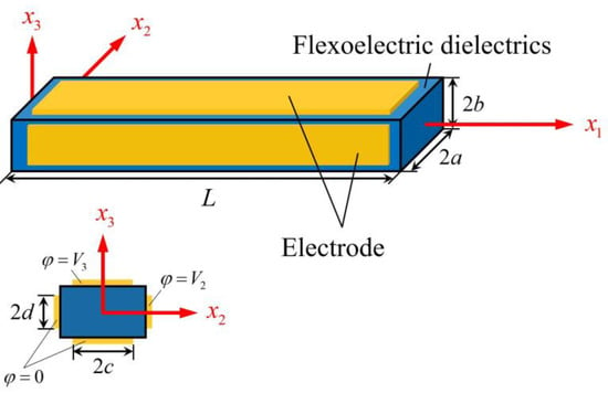
Figure 1.
A thin flexoelectric beam and coordinate system whose origin is at the center of the left face.
1-D equations for bending in the (x1,x3) plane were derived from Equations (1)–(3) in [20]. For the gryroscope application to be studied in the next section, we need to generalize the 1-D equations in [20] to the case of simultaneous bending in both of the the (x1,x2) and (x1,x3) planes. In this case, the displacement components are approximated by
which produce the following axial strain and strain gradients:
Since the lateral surfaces of the beam are electroded and the electric potential are functions of time only on ideal electrodes that we assume, the electric field is approximated by
The equations for bending are obtained by integrating Equation (1a) with i = 2 and 3 over the beam cross section, which results in [20]
where Q2 and Q3 are the transverse shear forces in the x2 and x3 directions, respectively, and A = 4ab is the area of the beam cross section. The integration of the products of Equation (1a) with x2 or x3 over the beam cross section yields the following shear force-bending moment relation [20]:
where M3 and M2 are moments associated with bending in the (x1,x2) and (x1,x3) planes, respectively. For thin beams, the rotatory inertia is neglected. The 1-D constitutive relations are obtained by integrating the relevant equations in Equation (2) and their products with x2 or x3 over a cross section. The results are
where
and are needed to calculate the charge on the electrodes. Substitutions from Equations (8) and (9), we can write Equation (7) as two equations for u1 and u2:
4. Analysis of a Flexoelectric Gyroscope
When the beam in Figure 1 is used as a gyroscope, it is rotating about the x1 axis with an angular rate Ω that is to be measured. We fixed the coordinate system to the rotating beam. In the rotating coordinate system, the effects of the centripetal and Coriolis accelerations can be taken into consideration through the following effective forces:
V2 is the known applied voltage that drives the beam into bending with u2. The effective Coriolis force then drives the beam into bending with u3, which produces V3, which is unknown. The charge on the electrode at x3 = b is given by
where Equation (9d) has been used. The current flowing out of this electrode is given by
Consider time-harmonic motions with the following complex notation
where , , U2, U3, , and are the complex amplitudes of V2, V3, u2, u3, Qe, and I3. i is the imaginary unit. ω is the time-harmonic frequency. The electrodes at x3 = ± b are connected by a circuit whose impedance is Z in harmonic motions, which provides the following circuit equation:
The substitution of Equations (12)–(15) into Equations (11) and (16) results in the following three equations for U2, U3, and :
Specifically, consider a simply supported beam with the following boundary conditions:
Equation (18) represents the simplest and most basic mounting of a beam, which was used in the first piezoelectric vibratory gyroscope [11]. The purpose of the present paper is to show that a vibrating flexoelectric beam can also operate as a gyroscope. Other mountings, such as a cantilever, can also be used, which changes the mathematical analysis but not the mechanism of the device. Therefore, other boundary conditions are not pursued here.
Equation (17a,b) form a system of linear ordinary differential equations. We look for its solution in the following form:
where k is undetermined. The substitution of Equation (19) into Equation (17a,b) gives two linear homogeneous algebraic equations:
For nontrivial solutions, the determinant of the coefficient matrix has to vanish, i.e.,
Equation (21) is a polynomial equation for k. We denote its eight roots by k(N), where N = 1, 2, …, 8. The corresponding nontrivial solutions of U2 and U3 are denoted by
Then, the general solution of Equation (17a,b) can be written as
where are undetermined constants. The substitution of Equation (23) into Equations (17c) and (18) yields nine linear algebraic equations for and . These equations are solved on a computer using MATLAB R2021a (Xi’an, China).
5. Numerical Results and Discussion
As a numerical example, consider a ceramic beam of BaTiO3 that is not poled and hence is nonpiezoelectric. The relevant material constants are C11 = 166 GPa, C12 = 77 GPa, C13 = 78 GPa, C33 = 162 GPa, C44 = 43 GPa, ϵ33 = ϵ22 = 12.6 × 10⁻⁹ C2/(N∙m2), and f3113 = 10−6 N/C. The elastic and dielectric constants are from [25]. The flexoelectric constant is from [18,26]. Examples of other materials that have been used for micro-beams are zinc oxide, barium sodium niobate, barium titanate [27], and strontium titanate [28], which, when unpoled, may be considered for flexoelectric gyroscope applications. In [29], a micro-beam of BaTiO3 with dimensions of 1.5, 3.2, and 11 μm was fabricated for experimental investigation. For our modeling analysis with the goal of demonstrating the basic operation of the gyroscope, the geometric parameters were chosen to be a = b = 5 μm, c = d = a/2, and L = 200 μm. Material damping is described by complex elastic constants Cpq(1 + i/Q) with Q = 102. The amplitude of the driving voltage is V2 = 100 volts. Z = ∞ is used for the open circuit output voltage. Ω = 3.6 × 10⁴ rad/s, which is much smaller than (approximately 1%) the first resonance frequency of the beam, which is 3.6 × 10⁶ rad/s. Some of these parameters may be varied separately below. We introduced Z2 as a unit for Z:
Figure 2a shows versus the driving frequency ω with three resonances. The third one is barely visible. For gyroscope application, we are mainly interested in the first resonance. , and the output voltage |V3| near the first resonance are shown in Figure 2b–d, respectively. u2 is driven by the applied V2 through flexoelectric coupling and is called the primary motion. u3 is due to the Coriolis force associated with Ω and is called the secondary motion. V3 is produced by u3 through flexoelectric coupling. They all assume double-peak resonances because of flexural vibrations in both directions, which is typical for vibratory piezoelectric gyroscopes.
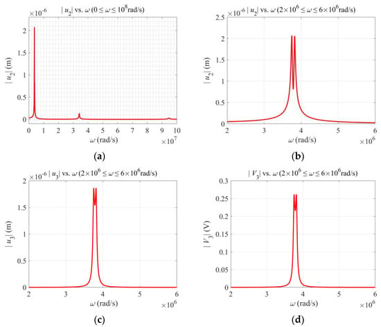
Figure 2.
Behavior near the first resonance. (a) Primary motion showing resonances. (b) Primary motion near the first resonance. (c) Secondary motion near the first resonance. (d) Output voltage near the first resonance.
Figure 3 shows the effects of various parameters on the output voltage near the first resonance. Figure 3a shows that a larger flexoelectric coefficient leads to a higher output, which is as expected. Figure 3b shows that the output voltage drops when the cross section deviates somewhat from a square. This is because, for a beam with a cross section not close to a square, the resonance frequencies of flexural vibrations in the x2 and x3 directions are not close. Hence, the gyroscope is not working in the optimal condition (the so-called double-resonant condition). Figure 3c shows that, when the impedance of the output circuit increases, the output voltage increases too. At the same time, the output current decreases correspondingly. Figure 3d shows that the output voltage is linear in Ω when Ω is small, which is ideal for angular rate sensing. For large values of Ω, the linearity is lost because Ω appears in Equation (17) in a complicated and nonlinear way.
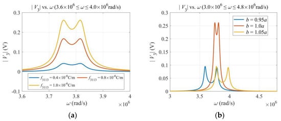
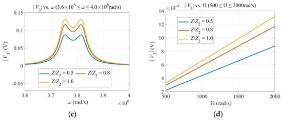
Figure 3.
Effects of various parameters. (a) Flexoelectric coefficient. (b) Dimensions of the cross section. (c) Impedance of the output circuit. (d) Angular rate Ω. ω = 3.7 × 10⁶ rad/s.
The output signal V3 for detecting Ω depends on several physical and geometric parameters; in particular, the driving frequency ω and the impedance Z of the output circuit as shown in Figure 2 and Figure 3, where ω and Z were varied one at a time. For a more comprehensive understanding of the behavior of the gyroscope, we plot V3 versus ω and Ω together in Figure 4a, and V3 versus ω and Z in Figure 4b, respectively. The curves in Figure 2 and Figure 3 are formed by intersections of the surfaces in Figure 4 with different vertical planes. It can be seen from Figure 4a that, when Ω is fixed, there are two peaks as ω varies. The two peak values increase with Ω monotonically when Ω is small and saturate when Ω is large. The distance between the two peaks also increases with Ω. In Figure 4b, when Z is fixed, there are two peaks as ω varies. The two peak values increase with Z monotonically. When Z is small, the output circuit is nearly shorted, with a small V3. When Z is large, the output circuit is nearly open, with a large and saturated V3. These agree with Figure 3c,d.
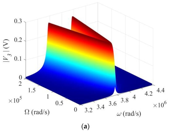
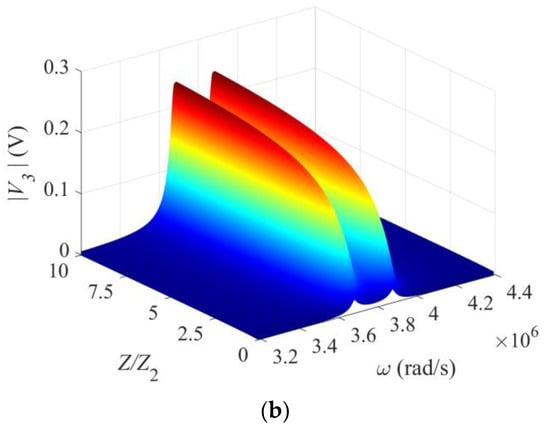
Figure 4.
Three-dimensional views of the output voltage. (a) V3 versus ω and Ω. Z = ∞. (b) V3 versus ω and Z. Ω = 105 rad/s.
6. Conclusions
It is shown theoretically that a micro-beam in flexural vibrations excited and detected flexoelectrically can be used to make a gyroscope to detect an angular rate. Compared to conventional piezoelectric beam gyroscopes, the flexoelectric beam gyroscope proposed has a simpler structure or electrode configuration. The one-dimensional model developed is effective in describing the basic behaviors of the beam flexoelectric gyroscope.
Author Contributions
Conceptualization, J.Y.; methodology, J.Y. and Y.Q.; software, Y.Q.; validation, Y.Q.; formal analysis, Y.Q.; investigation, Y.Q.; resources, F.J. and Y.Q.; data curation, Y.Q.; writing—original draft preparation, J.Y.; writing—review and editing, J.Y.; visualization, Y.Q.; supervision, F.J.; project administration, F.J.; funding acquisition, F.J. and Y.Q. All authors have read and agreed to the published version of the manuscript.
Funding
This research was funded by the National Natural Science Foundation of China (No. 12072253, Feng Jin), 111 Project version 2.0 (Feng Jin), and the Fundamental Research Funds for the Central Universities (xzy022020016, Yilin Qu).
Data Availability Statement
Not applicable.
Conflicts of Interest
The authors declare no conflict of interest. The funders had no role in the design of the study; in the collection, analyses, or interpretation of data; in the writing of the manuscript; or in the decision to publish the results.
References
- Burdess, J.S.; Harris, A.J.; Cruickshank, J.; Wood, D.; Cooper, G. A review of vibratory gyroscopes. Eng. Sci. Edu. J. 1994, 3, 249–254. [Google Scholar] [CrossRef]
- Soderkvist, J. Micromachined gyroscopes. Sens. Actuators A 1994, 43, 65–71. [Google Scholar] [CrossRef]
- Yang, J.S. A review of analyses related to vibrations of rotating piezoelectric bodies and gyroscopes. IEEE Trans. Ultrason. Ferroelect. Freq. Contr. 2005, 52, 698–706. [Google Scholar] [CrossRef] [PubMed]
- Loveday, P.W. Analysis and Compensation of Imperfection Effects in Piezoelectric Vibratory Gyroscopes. Ph.D. Dissertation, Virginia Polytechnic Institute and State University, Blacksburg, VA, USA, 1999. [Google Scholar]
- Fang, H.Y. Vibrations of a Rotating Piezoelectric Body and Applications in Gyroscopes. Ph.D. Dissertation, University of Nebraska–Lincoln, Lincoln, NE, USA, 2000. [Google Scholar]
- Liang, F.; Liang, D.D.; Qian, Y.J. Dynamical analysis of an improved MEMS ring gyroscope encircled by piezoelectric film. Int. J. Mech. Sci. 2020, 187, 105915. [Google Scholar] [CrossRef]
- Hodjat-Shamami, M.; Ayazi, F. Eigenmode operation of piezoelectric resonant gyroscopes. Microsyst. Nanoeng. 2020, 6, 108. [Google Scholar] [CrossRef] [PubMed]
- Obitani, K.; Qian, J.; Tsuchiya, T.; Araya, K.; Yachi, M. Electrode design of single crystal lithium niobate piezoelectric disk gyroscope. In Proceedings of the 2020 IEEE International Symposium on Inertial Sensors and Systems (INERTIAL), Hiroshima, Japan, 23–26 March 2020; pp. 1–2. [Google Scholar]
- Qu, T.; Zhou, G.; Xue, X.; Teng, J. Cylindrical shell vibration gyroscope excited and detected by high-temperature-sintered piezoelectric ceramic electrodes. Sensors 2020, 20, 5972. [Google Scholar] [CrossRef] [PubMed]
- Larkin, K.; Ghommem, M.; Serrano, M.; Abdelkefi, A. A review on vibrating beam-based micro/nano-gyroscopes. Microsyst. Technol. 2021, 27, 4157–4181. [Google Scholar] [CrossRef]
- Gates, W.D. Vibrating angular rate sensor may threaten the gyroscope. Electronics 1968, 41, 130–134. [Google Scholar]
- Soderkvist, J. Piezoelectric beams and vibrating angular rate sensors. IEEE Trans. Ultrason. Ferroelec. Freq. Contr. 1991, 38, 271–280. [Google Scholar] [CrossRef]
- Yang, J.S.; Fang, H.Y. Analysis of a rotating elastic beam with piezoelectric films as an angular rate sensor. IEEE Trans. Ultrason. Ferroelec. Freq. Contr. 2002, 49, 798–804. [Google Scholar] [CrossRef] [PubMed]
- Sahin, E.; Dost, S. A strain-gradients theory of elastic dielectrics with spatial dispersion. Int. J. Engng. Sci. 1988, 26, 1231–1245. [Google Scholar] [CrossRef]
- Tagantsev, A.K. Piezoelectricity and flexoelectricity in crystalline dielectrics. Phys. Rev. B 1986, 32, 5883–5889. [Google Scholar] [CrossRef] [PubMed]
- Shen, S.; Hu, S. A theory of flexoelectricity with surface effect for elastic dielectrics. J. Mech. Phys. Solids 2010, 58, 665–677. [Google Scholar] [CrossRef]
- Zhang, R.; Liang, X.; Shen, S. A Timoshenko dielectric beam model with flexoelectric effect. Meccanica 2015, 51, 1181–1188. [Google Scholar] [CrossRef]
- Zhou, Z.D.; Yang, C.P.; Su, Y.X.; Huang, R.; Lin, X.L. Electromechanical coupling in piezoelectric nanobeams due to the flexoelectric effect. Smart Mater. Struct. 2017, 26, 095025. [Google Scholar] [CrossRef]
- Hu, Y.T.; Wang, J.N.; Yang, F.; Xue, H.; Hu, H.P.; Wang, J. The effect of first-order strain gradient in micro piezoelectric-bimorph power harvester. IEEE Trans. Ultrason. Ferroelec. Freq. Contr. 2011, 58, 849–852. [Google Scholar]
- Qu, Y.L.; Jin, F.; Yang, J.S. Buckling of flexoelectric semiconductor beams. Acta Mech. 2021, 232, 2623–2633. [Google Scholar] [CrossRef]
- Yang, W.J.; Liang, X.; Shen, S.P. Electromechanical responses of piezoelectric nanoplates with flexoelectricity. Acta Mech. 2015, 226, 3097–3110. [Google Scholar] [CrossRef]
- Ray, M.C. Mesh free model of nanobeam integrated with a flexoelectric actuator layer. Compos. Struct. 2017, 159, 63–71. [Google Scholar] [CrossRef]
- Fan, M.; Min, H. Active actuating of a simply supported beam with the flexoelectric effect. Materials 2020, 13, 1735. [Google Scholar] [CrossRef] [Green Version]
- Mase, G.T.; Mase, G.E. Continuum Mechanics for Engineers, 2nd ed.; CRC Press: Boca Raton, FL, USA, 1990. [Google Scholar]
- Auld, B.A. Acoustic Fields and Waves in Solids; Wiley: New York, NY, USA, 1973. [Google Scholar]
- Shu, L.; Wei, X.; Pang, T.; Yao, X.; Wang, C. Symmetry of flexoelectric coefficients in crystalline medium. J. Appl. Phys. 2011, 110, 104106. [Google Scholar] [CrossRef]
- Zaki, N.A.F.; Aziz, A.A.; Khairudin, N.; Burham, N. Simulation of zinc oxide, barium sodium niobate, and barium titanate as lead-free piezoelectric materials. In Proceedings of the 2021 IEEE Regional Symposium on Micro and Nanoelectronics (RSM), Kuala Lumpur, Malaysia, 2–4 August 2021; pp. 38–41. [Google Scholar]
- Bhaskar, U.; Banerjee, N.; Abdollahi, A.; Wang, Z.; Schlom, D.G.; Rijnders, G.; Catalan, G. A flexoelectric microelectromechanical system on silicon. Nat. Nanotech. 2016, 11, 263–266. [Google Scholar] [CrossRef] [PubMed]
- Yamaguchi, H.; Tatami, J.; Iijima, M. Measurement of mechanical properties of BaTiO3 layer in multilayered ceramic capacitor using a microcantilever beam specimen. J. Ceram. Soc. Jpn. 2019, 127, 335–338 2019. [Google Scholar] [CrossRef] [Green Version]
Publisher’s Note: MDPI stays neutral with regard to jurisdictional claims in published maps and institutional affiliations. |
© 2022 by the authors. Licensee MDPI, Basel, Switzerland. This article is an open access article distributed under the terms and conditions of the Creative Commons Attribution (CC BY) license (https://creativecommons.org/licenses/by/4.0/).