
Texturing Technologies for Plastics Injection Molding: A Review


Abstract
1. Introduction
2. Mechanical Machining
2.1. Micro-Milling
2.2. Diamond Tool Micro-Milling
2.3. Ultrasonic-Assisted Machining
2.4. Abrasive Jet Machining
3. Electrochemical Etching
3.1. Chemical Etching
- Workpiece preparation and cleaning with an alkaline solution and water. Chemical cleaning ensures proper adhesion of the maskant layer on the metal surface. The solvent selection for the chemical cleaning depends on the maskant kind, the workpiece material, the workpiece surface finish, and the required texture depth. A proper surface cleaning prevents the debonding of the mask, which will result in stray etching.
- Masking of the workpiece to selectively cover specific areas of the surface. Different masking techniques are available depending on the workpiece’s dimension, the characteristic texture dimension, the required accuracy, and the etching depth. Cut and peel off consists of applying an even coating and peeling off the marked areas. Photochemical masking exploits a photoresist coating that is selectively developed to mask and free certain areas and jet printing techniques, to name a few. As the texture features dimensions shrink down to the microscale, photochemical masking techniques are preferred (Zhang et al., 2016). This process guarantees a high texture shape accuracy without being substantially affected by the pattern complexity. The maskant material has to bond tightly to the workpiece surface and has to be resistant to the etchant.
- Immersion of the workpiece in the etchant bath. Besides the workpiece and maskant materials, the etchant selection is usually driven by process factors, such as surface finish and material removal rate and etchant availability, cost, and sustainability.
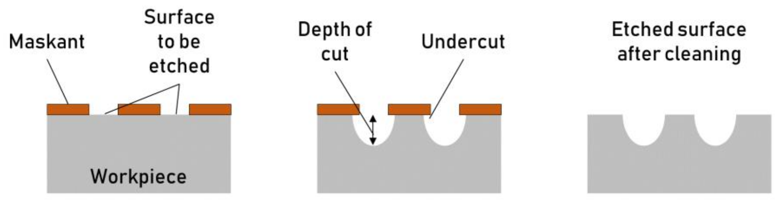
- Etching of the unmasked areas. The etchant bath can be agitated and heated to increase the material removal rate and uniformity. The material removal rate is typically low and develops in two directions, downward—depth of cut—and laterally—undercut—from the exposed surface (Figure 5). The ratio between the undercut and the depth of cut is known as the “etch factor.” The etch parameter’s control is challenging and requires a deep understanding of the process phenomena, especially when etching texture with small features.
- Workpiece chemical rinsing to remove the mask layer and etchant residues. At the end of the process, the etchant is cleaned, and the mask has to be removed.
- Final workpiece rinsing. Finally, as the mask is removed, a final rinsing step with clear water is carried out to remove any chemical used for etching or mask removal.

3.2. Electro-Chemical Machining
3.3. Electric Discharge Machining
4. Thermoelectric Engraving
4.1. Laser Texturing
4.1.1. Laser Writing
4.1.2. Through Mask Laser Texturing
4.1.3. Ultrafast Laser Texturing
4.1.4. Direct Laser Interface Patterning (DLIP)
4.2. High-Energy Beam Machining
4.2.1. Electron Beam Machining
4.2.2. Focused Ion-Beam Machining
5. Additive Manufacturing
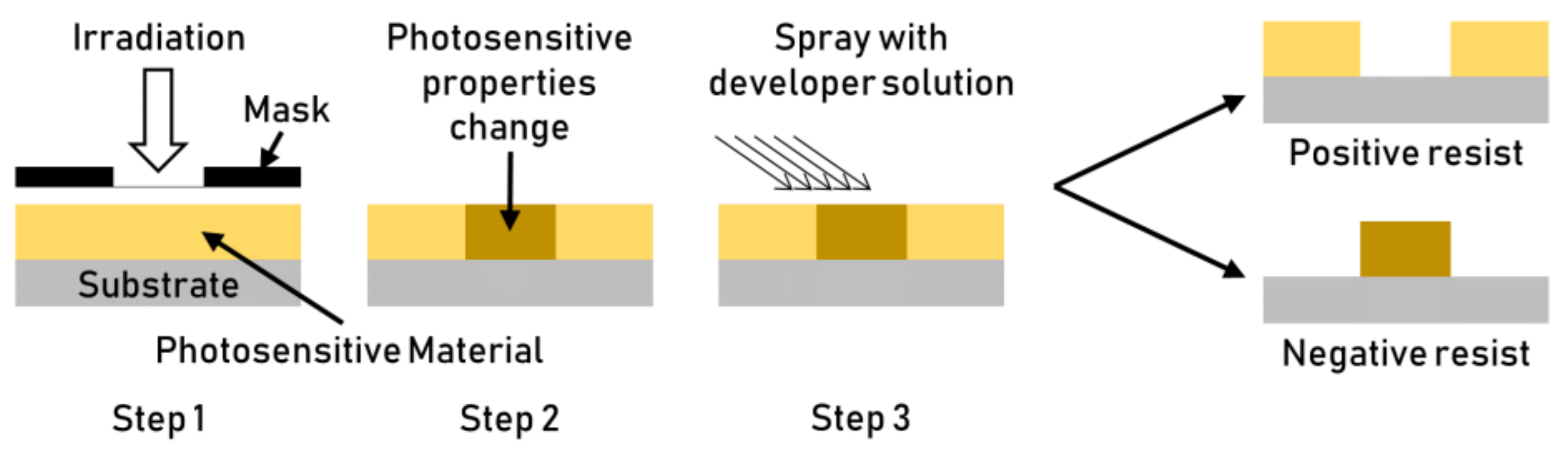
5.1. Lithography
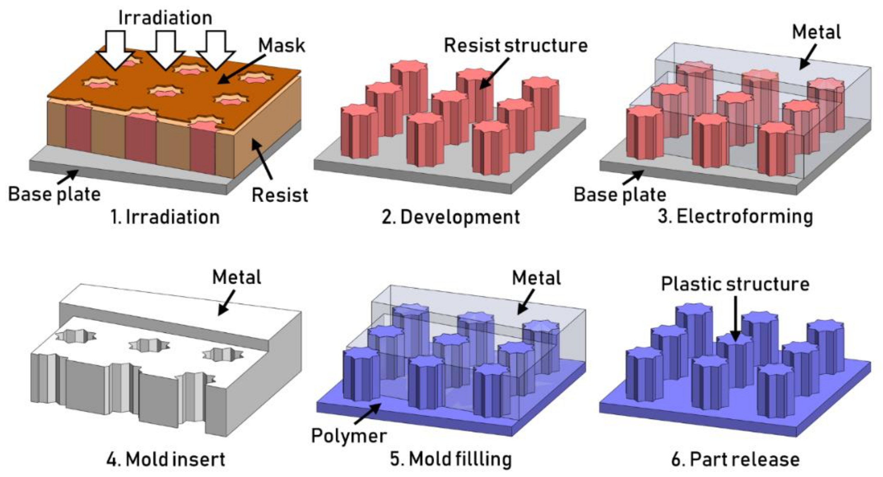
5.2. LIGA
5.3. Maskless Additive Manufacturing
5.4. 3D Printed Soft Tooling
6. Advantages and Limitations
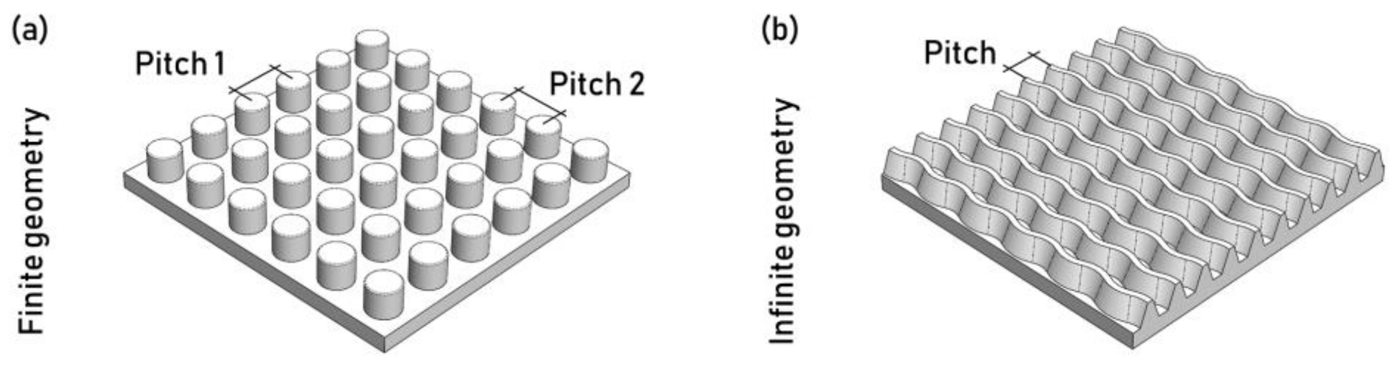
6.1. Geometric Texture Parameters
- The spatial pitch of the pattern, i.e., the distance between consecutive features.
- The features’ cross-section geometry, such as their diameter or width.
- The feature height or depth, i.e., the distance from the substrate to the top or bottom of the features.
- The aspect ratio, i.e., the ratio between the feature height or depth and its width.
6.2. Process Texturing Capabilities
- Texture scale—the overall dimension of the desired features has to be defined in agreement with the different texturing technologies’ capabilities and limitations;
- Geometrical flexibility—the texturing technology property of generating features on surfaces with different complexity, from planar to three-dimensional to free-form needs to be considered;
- Process–property relation—the ability to create specific texture features on the selected material needs to be evaluated. Then, the damage produced during processing should be considered;
- Economics—different texturing technologies are characterized by significantly different costs but they also offer different possibilities.
6.3. Achievable Shapes and Dimensions
- Micro-milling technologies are used to machine three-dimensional textures with features that may be as small as 10 microns with aspect ratio of 3:4 [10]. The CNC control guarantees high shape consistency (i.e., the capability to produce the same shape) across the texture. However, the shape accuracy (i.e., the capability of producing the desired shape) is affected by the material grain size and the presence of burrs. The latter is very difficult to remove at the micro-scale. The machining of smaller grain size steel showed much higher shape accuracies [60]. Process modifications, such as diamond tool micro-milling or ultrasonic-assisted machining, were introduced to limit burrs formation.
- In the AJM process, the mask defines the minimum feature dimension, typically in the order of 100 μm. The mask material has to be tough enough to withstand the erosion of the abrasive jet. Aspect ratios for this process are usually low (around 0.5). The shape accuracy can be enhanced by choosing different abrasive particles. The size, the shape, and the material hardness of the abrasive have a substantial effect on the shape accuracy [21]. Smaller particles with few sharp edges and relatively low hardness can produce better textures.
- A large variety of structure shapes can be obtained using µEDM with dimensions down to tenths of microns. The aspect ratio is mainly constrained by the flushing efficiency [26] and the maximum values are about 2. Indeed, flushing is increasingly challenging for a higher aspect ratio, and the adequate electrical conditions for the spark may not be reached. Flushing can also affect the stability of slender electrodes when the flushing velocity is increased. The feature shape accuracy is mainly linked to the spark crater and tool wear, which can be minimized by reducing the spark energy. Tool wear is avoided in ECMM, resulting in higher texture consistency. The machinable features and aspect ratios are comparable to µEDM for the conventional process, and they depend on process parameters like voltage and electrolyte purity. Ultrasound-assisted ECMM was introduced to push the feature dimensions down to 1 µm and the aspect ratio to 3 [29]. The tool vibration enhances the electrolyte flushing and heat removal.
- Masked processes, such as TMECM or chemical etching, are used to manufacture 2.5-dimensional textures. The achievable aspect ratio is about 1, but textures with lower aspect ratios are usually machined with these processes. The electrolyte or the etchant is flushed over the surface to maintain a homogenous material ablation and obtain better structure consistency throughout the entire surface. In both processes, etching can create undesired undercuts by removing material under the mask. Hence, larger masks are used to consider this effect.
- Laser-based technologies generate different features based on how the beam light is delivered and focused on the surface. In laser writing, a large variety of features as small as 20 µm can be obtained, with an aspect ratio up to 3 [31]. The interference phenomena that characterize ultrafast laser texturing and DLIP result in smaller feature dimensions, down to 100 nanometers. For these technologies, the texture dimensions depend on the light properties (i.e., wavelength) and process conditions (i.e., irradiance and scanning speed). The upper limit on feature size is around 100 µm for LIPSS obtained using ultrafast laser texturing and 500 µm for DLIP [39]. The shapes obtained with these technologies are limited due to the tight correlation with laser light properties, such as polarization and wavelength. Ultrafast laser texturing and DLIP can be used to generate hierarchical textures. The primary shape defects of laser-based texturing technologies are recasts around the engraved area and thermal micro-cracks. As a consequence, texture consistency and shape accuracy are the main challenges.
- When a mask is used for laser texturing, the minimum feature dimension is constrained by the diffraction effects when the laser light crosses the mask. Features dimensions as small as 5 µm can be engraved with aspect ratios smaller than 0.5. The texture consistency along the surface is typically high but the shape accuracy is limited by recast and thermal micro-cracks. High-energy beam techniques are used to generate three-dimensional structures with small dimensions (i.e., down to 100 nm for FIBM) with aspect ratio not bigger than 1. The machined features are typically accurate and precise.
- A wide range of three-dimensional surface features with dimensions as small as 100 µm can be manufactured using additive manufacturing technologies. DED’s working principle makes the achievable features bigger and less accurate than those obtained using SLM. SLM offers the possibility of achieving higher aspect ratios (i.e., up to 4 for SLM and up to 2 for DED). The minimum feature dimensions and the shape accuracy are affected by the powder particle dimensions, which are typically not smaller than a few tens of microns [49]. Typical defects are the bridging between different surface features, balling, non-evacuated powders, or internal voids.
- Lithographic techniques manufacture 2.5-dimensional features with high aspect ratios, with dimensions as small as few nanometres. Simple three-dimensional features can be manufactured using the LIGA technique. However, features cannot be smaller than 500 nm. These techniques result in textures characterized by high consistency and accuracy.
6.4. Geometrical Flexibility
- In mechanical machining technologies, tool movements are CNC controlled along multiple axes. Thus, the equipment is highly flexible and can be used to texture complex surfaces. However, milling-based technologies are limited by the length-to-diameter ratio of the cutting tool [10,15]. Abrasive jet machining is more flexible when texturing hard-to-approach areas, as the jet can be optimized to travel a longer distance on the workpiece [21]. However, the generation of regular patterns requires a mask, limiting the ability to work on complex free-form surfaces. In comparison, abrasive jet machining can be used to obtain random textures on complex products.
- The use of a mask introduces geometrical limitations for electrochemical etching processes, such as chemical etching and through mask electro-chemical machining. Maskless technologies can be used for more complex geometries, such as micro electro-discharge machining and electrochemical micromachining. These processes can exploit simple shape tools or pre-patterned ones to texture different workpiece geometries [8]. In this case, the effective flush of the debris from the working area is crucial, which defines the limits for geometrical complexity.
- Laser-based thermo-electric engraving technologies allow good geometrical flexibility. Laser writing is the most flexible technology among the four laser-related technologies considered since the optical head is mounted on a five-axis CNC machine. When using an ultrafast pulsed laser, issues related to beam handling reduce the flexibility for ULT and DLIP. These technologies cannot exploit CNC machines because of the high pulse power. Hence, they use mirror systems to redirect the laser beam to specific surface locations. However, the need to deliver an unchanged laser beam to the workpiece surface makes this approach complex and limited. Indeed, ultrafast pulsed laser technologies exploit the laser beam’s light wave characteristics not just thermal energy. Similarly, high-energy beam machining techniques (i.e., EBM and FIBM) require advanced equipment to handle the beam, limiting the workpiece dimension and allowing the texturing of 2D surfaces only.
- Lithography and LIGA technologies allow texturing of planar surfaces only. Additive manufacturing texturing technologies have higher flexibility. For example, DED nozzles are often mounted on multi-axis CNC machines. However, substantial limitations should be considered for concave geometries’ texturing, due to the dimensions of the nozzle and the short powder jet length. The SLM process allows texturing free-form surfaces only when the product and the texture are realized in the same process. However, the processing times can be very long. Conversely, if SLM is used to texture an existing product, only planar surfaces are allowed but the texturing time is significantly shorter.
6.5. Material–Process Relationship
- Textures obtained with mechanical machining processes are characterized by residual stresses, affecting the texture strength and wear resistance. The tool contact creates these defects as a result of the ablation and material removal. Textures can be micro-milled on a wide range of materials, and the quality is mainly affected by the grain size. The edge radius of cutting tools can be as small as the grain size, and machining instabilities can occur. Hence, for high-accuracy applications, materials with finer grain size are preferred. Similar phenomena are also crucial in abrasive jet machining, in which the particle size, shape, and hardness, are selected to avoid the inclusion of particles inside the workpiece.
- Electro-chemical etching techniques result in stress-free textures. However, selecting the appropriate etchant for a specific substrate material is crucial to avoid chemical damage to the workpiece surface. The chemical modifications of the exposed surface are evident even after rinsing, but they are a concern only for a specific application (e.g., clean room tools). The chemical modifications of the surface are minor with ECMM. However, if inclusions characterize the metal substrate, those can affect the resulting properties.
- In the EDM process, the texture is generated by thermal phenomena, such as localized melting and vaporization. Thermal stresses on a superficial layer characterize textures obtained with this technology. However, structure and crystallinity can be modified further down in the workpiece, thus defining the Heat-Affected Zone (HAZ). Thermo-electric processes are always characterized by the presence of a HAZ on the textured surface.
- Laser-based texturing technologies typically show thermal micro-cracks and recasts. The fast cooling of the melted material over the surface that is not ablated produces micro-cracks. The condensation of vaporized material over the surface produces the recasts. Pulsed lasers were introduced to reduce the HAZ and enhance machining accuracy. Ultrafast pulsed laser processing is defined as a “cold process” because the HAZ can be neglected. However, surface oxidation can be a problem with these technologies. The HAZ is also minimal for high-energy beam machining, but EBM and FIBM are executed in a vacuum environment to avoid oxidation.
- Additive manufacturing texturing can only be carried out with materials that are not prone to oxidation, such as stainless steel. The oxidizing of the powders ultimately compromises the texturing process. Residual thermal stresses, micro-cracks, and internal porosities are the most common defects of this process. Porosities, inclusions, and residual stresses are common in the LIGA process because of the electroplating with nickel.
6.6. Economics
- Cost of the materials needed to generate the texture (e.g., metal powder for an SLS process or nickel for LIGA);
- Cost of the equipment and auxiliary needed for a specific texturing technology;
- Cost associated with the texture generation (e.g., required to operate an EDM machine or consumable used in a chemical-etching process);
- Quality control and characterization costs (e.g., access to advanced microscopy equipment to characterize a directly laser-written texture).
- Mechanical machining texturing uses specific multi-axis CNC machines with high-spindle speeds, a rigid structure, and a temperature-controlled environment. Machining tools typically have a short life due to high machining speeds and small tool dimensions. Harder tools (e.g., coated or diamond tools) are often exploited to decrease the tool wear despite the higher cost. Moreover, micro-milling tools are significantly more expensive (i.e., up to 10 times higher) than conventional ones. The machining process is characterized by low MMR and so low texturing speed. The latter depends on the material hardness, texture complexity, and workpiece geometry. Overall, the costs are mitigated by the short setup time and the near-net-shape that are typically manufactured. These processes are characterized by high energy efficiency and a low environmental footprint. The primary ecologic concern is the lubricant, typically filtered and recirculated by the machine, but it must be correctly disposed of at the end of life.
- Multiple steps and low MMR characterize electrochemical etching. However, the economics are mitigated by the ability to create textures on large areas. The need for chemical solvents makes the operation costs higher, as specific health and safety procedures need to be implemented. In ECMM, multiple-axis CNC machines are used, resulting in higher MMR. Moreover, the lack of contact between the tool and the workpiece reduces the tooling wear and costs. During processing, handling, and disposal of electrolytes has to be considered. However, it is less hazardous for operators and the environment compared to chemical etchants. µEDM is a net-shape texturing technology, but the manufacturing of small and low surface finish textures requires small spark energy that leads to low MMR. Increased throughput is achieved with multiple roughing passes before finishing. With this strategy, the depth of the craters obtained with roughing might limit the achievable surface finish.
- Laser-based texturing is controlled using multiple-axis CNC machines. The equipment cost is high for ultrafast lasers, especially for femtosecond laser sources which require moving lenses to create complex optical paths. Texturing speed varies significantly with specific laser technologies. Masked-laser texturing has higher throughput than laser writing due to its ability to manufacture larger areas. Ultrafast laser texturing and DLIP exhibit excellent texturing speed, considering the achievable texture dimensions (from 10−2 to 102 μm). Laser texturing is an environmentally sound technology that does not require handling any hazardous substance.
- EBM and FIBM require advanced and costly equipment. High-vacuum chambers are used to focus high-energy beams on the surface. The expensive setup is also limited when considering the size of the workpiece. Moreover, texturing speed is extremely low, and energy efficiency is poor. The economics of this technology are justified for high-end products that require unique three-dimensional structures with high accuracy.
- Lithography techniques are costly because of the multiple steps required for texturing. Moreover, the equipment and consumables (such as masks) are expensive and handled by specialty workers. The technology owes its large diffusion to the ease of scale-up and high throughput. Manufacturing facilities for photolithography require high investments (about USD 30 million) but allow large-scale manufacturing.
- Powder-based additive manufacturing processes are characterized by high setup, processing, and material costs. A protective atmosphere must be created within a CNC machine to avoid oxidation of the powder. Powder handling involves health safety concerns, thus requiring specific handling tools and storage. In texturing tends that are slow, however, the design flexibility makes the technology attractive for a few specific applications.
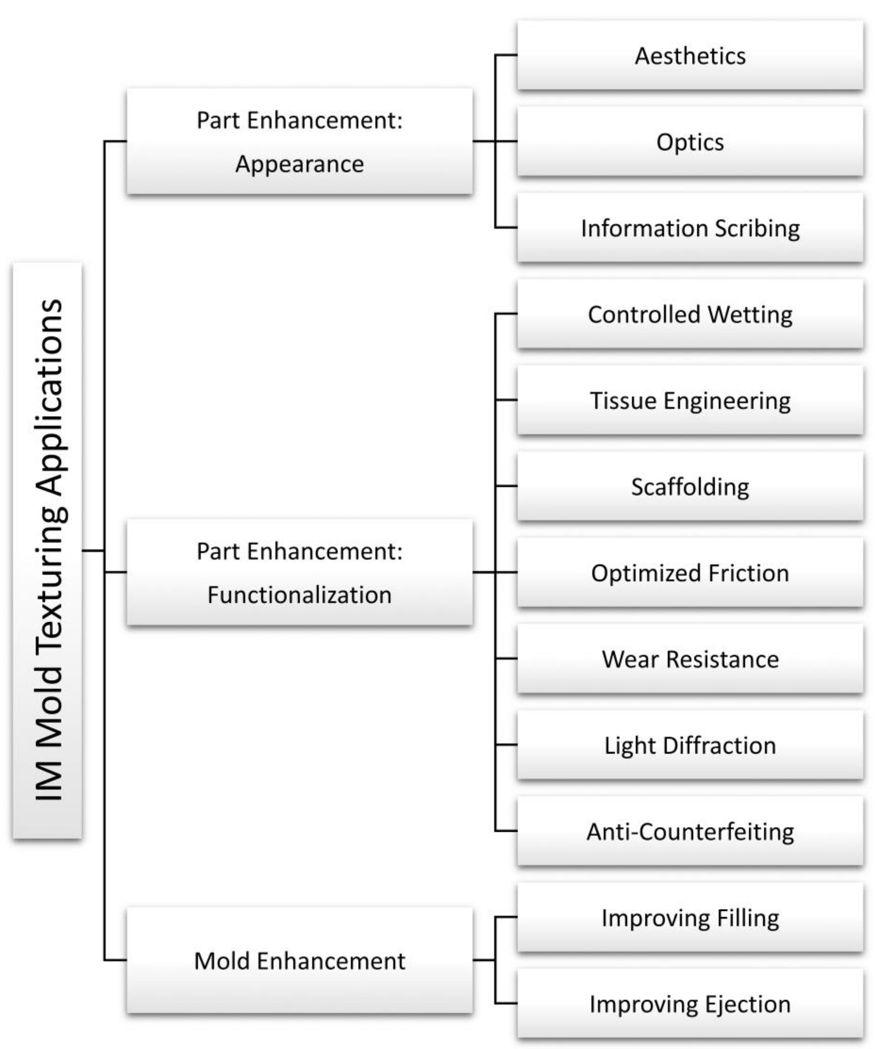
7. Applications of Texturing in Injection Molding
7.1. Aesthetic Texturing
7.2. Optics Functionalization
7.3. Information Scribing
7.4. Structural Colors
7.5. Controlled Wetting
7.6. Biomedical Functionalization
7.7. Controlled Friction
7.8. Tool Surface Functionalization
7.8.1. Filling
7.8.2. Ejection
8. Conclusions
- Chemical etching is the fastest technology and allows texturing of large surfaces. However, the structures that can be obtained are not very small and not very accurate. The most significant applications are for the automotive industry, which uses the technology for interior parts’ aesthetic texturing.
- The smallest texture can be manufactured using either EBM or FIBM. Both technologies are very accurate but extremely slow, limiting their diffusion to niece applications and small surfaces. The main applications, still limited to research labs and clean room environments, are high-end biomedical and electronics.
- Micro-milling is sensitive to the dimensions of the feature. The smaller is the texture, the slower is the process. Conventional micro-milling allows texturing down to 100 μm, while smaller textures (i.e., down to 20 μm) can be achieved using the ultrasound-assisted process. The most significant applications are headlight diffractors, for which sub-millimeter scale prisms are textured on injection mold surfaces.
- The μEDM texturing technology is susceptible to the required surface finish. Relatively smooth surfaces can be manufactured using low-spark energy while significantly decreasing the texturing speed. Texturing injection molds using this technology allows for overcoming the size limitations of micro-milling.
- The ECMM is faster than μEDM as it exploits the chemical energy to remove the material. Moreover, the more homogeneous material removal results in a better surface finish.
- When considering additive manufacturing technologies, DED is faster than SLM because the powder is deposited by the nozzle and sintered by the co-axial beam. However, SLM can manufacture smaller and more accurate texture features.
- DLIP is the fastest laser technology because it exploits the pattern interference to create features at specific locations on the surface. The functioning principles limit the type of textures that can be manufactured. However, the Through Mask Laser Texturing overcomes this limitation when considering textures with bigger feature sizes.
- Direct laser writing is a slow technology because of the direct material ablation, and the spot size dimension limits the feature size. Smaller textures, with limited geometries, can be realized using a femtosecond laser.
- The AJM texturing process is used for its high velocity and its cleanliness. However, it is not very accurate, and the feature definition is typically not high.
- The successful utilization of a texture for injection molding requires the evaluation of polymer processing aspects that are not discussed in this work; they are, however, well-established in the literature.

Author Contributions
Funding
Institutional Review Board Statement
Informed Consent Statement
Data Availability Statement
Conflicts of Interest
References
- Hansen, H.N.; Hocken, R.J.; Tosello, G. Replication of micro and nano surface geometries. CIRP Ann. Manuf. Technol. 2011, 60, 695–714. [Google Scholar] [CrossRef]
- Masato, D.; Sorgato, M.; Lucchetta, G. Analysis of the influence of part thickness on the replication of micro-structured surfaces by injection molding. Mater. Des. 2016, 95, 219–224. [Google Scholar] [CrossRef]
- Hernández, P.; Murawko, A.; Martínez, J.; Peláez, G.; Ares, E. Replication of micro laser textures by injection molding. Procedia Eng. 2013, 63, 885–894. [Google Scholar] [CrossRef][Green Version]
- Masato, D.; Sorgato, M.; Lucchetta, G. Characterization of the micro injection-compression molding process for the replication of high aspect ratio micro-structured surfaces. Microsyst. Technol. 2017, 23, 3661–3670. [Google Scholar] [CrossRef]
- Kolew, A.; Münch, D.; Sikora, K.; Worgull, M. Hot embossing of micro and sub-micro structured inserts for polymer replication. Microsyst. Technol. 2011, 17, 609–618. [Google Scholar] [CrossRef]
- Jucius, D.; Guobiene, A.; Grigaliunas, V. Surface texturing of polytetrafluoroethylene by hot embossing. Appl. Surf. Sci. 2010, 256, 2164–2169. [Google Scholar] [CrossRef]
- Shivaprakash, N.K.; Zhang, J.; Panwar, A.; Barry, C.; Truong, Q.; Mead, J. Continuous manufacturing of reentrant structures via roll-to-roll process. J. Appl. Polym. Sci. 2019, 136, 46980. [Google Scholar] [CrossRef]
- Gachot, C.; Rosenkranz, A.; Hsu, S.M.; Costa, H.L. A critical assessment of surface texturing for friction and wear improvement. Wear 2017, 372–373, 21–41. [Google Scholar] [CrossRef]
- Pratap, T.; Patra, K. Micro ball-end milling—An emerging manufacturing technology for micro-feature patterns. Int. J. Adv. Manuf. Technol. 2018, 94, 2821–2845. [Google Scholar] [CrossRef]
- Câmara, M.A.; Rubio, J.C.C.; Abrão, A.M.; Davim, J.P. State of the Art on Micromilling of Materials, a Review. J. Mater. Sci. Technol. 2012, 28, 673–685. [Google Scholar] [CrossRef]
- Parenti, P.; Masato, D.; Sorgato, M.; Lucchetta, G.; Annoni, M. Surface footprint in molds micromilling and effect on part demoldability in micro injection molding. J. Manuf. Processes 2017, 29, 160–174. [Google Scholar] [CrossRef]
- Davim, J.P.; Jackson, M.J. (Eds.) Nano and Micromachining; ISTE-Wiley: London, UK, 2009. [Google Scholar]
- McCormick, M.; Deboer, C.M. Micromachining techniques, fixturing and end mill selection in high-precision VMC parts. Mach. Technol. 2006, 3. Available online: https://jglobal.jst.go.jp/en/detail?JGLOBAL_ID=200902251048224045 (accessed on 1 June 2022).
- Oliaei, S.N.B.; Karpat, Y. Influence of tool wear on machining forces and tool deflections during micro milling. Int. J. Adv. Manuf. Technol. 2016, 84, 1963–1980. [Google Scholar] [CrossRef]
- Wu, T.; Cheng, K. Micro milling: The state-of-the-art approach towards applications. In Micro-Cutting: Fundamentals and Applications, 1st ed.; Cheng, K., Huo, D., Eds.; Wiley: Chichester, UK, 2013; pp. 185–226. [Google Scholar] [CrossRef]
- Brinksmeier, E.; Gläbe, R.; Schönemann, L. Review on diamond-machining processes for the generation of functional surface structures. CIRP J. Manuf. Sci. Technol. 2012, 5, 1–7. [Google Scholar] [CrossRef]
- Kalpakjian Serope, S.S.R. Manufacturing Engineering and Technology: Machining, 8th ed.; Pearson: Hoboken, NJ, USA, 1991. [Google Scholar]
- Yang, Z.; Zhu, L.; Zhang, G.; Ni, C.; Lin, B. Review of ultrasonic vibration-assisted machining in advanced materials. Int. J. Mach. Tools Manuf. 2020, 156, 103594. [Google Scholar] [CrossRef]
- Jain, V.K. Advanced Machining Processes; Allied Publisher: Johannesburg, South Africa, 2009. [Google Scholar]
- Xu, S.; Kuriyagawa, T.; Shimada, K.; Mizutani, M. Recent advances in ultrasonic-assisted machining for the fabrication of micro/nano-textured surfaces. Front. Mech. Eng. 2017, 12, 33–45. [Google Scholar] [CrossRef]
- Melentiev, R.; Fang, F. Recent advances and challenges of abrasive jet machining. CIRP J. Manuf. Sci. Technol. 2018, 22, 1–20. [Google Scholar] [CrossRef]
- Wensink, H. Fabrication of Microstructures by Powder Blasting; University of Twente: Enshede, The Netherlands, 2002. [Google Scholar]
- Park, D.S.; Seo, T.I.; Cho, M.W. Mechanical etching of micro pockets by powder blasting. Int. J. Adv. Manuf. Technol. 2005, 25, 1098–1104. [Google Scholar] [CrossRef]
- Bruzzone, A.A.G.; Costa, H.L.; Lonardo, P.M.; Lucca, D.A. Advances in engineered surfaces for functional performance. CIRP Ann. Manuf. Technol. 2008, 57, 750–769. [Google Scholar] [CrossRef]
- Patel, D.; Jain, V.K.; Ramkumar, J. Micro texturing on metallic surfaces: State of the art. Proc. Inst. Mech. Eng. Part B J. Eng. Manuf. 2016, 232, 941–964. [Google Scholar] [CrossRef]
- Ho, K.H.; Newman, S.T. State of the art electrical discharge machining (EDM). Int. J. Mach. Tools Manuf. 2003, 43, 1287–1300. [Google Scholar] [CrossRef]
- Maradia, U.; Filisetti, E.; Boccadoro, M.; Roten, M.; Dutoit, J.M.; Hengsberger, S. Increasing the Injection Moulding Productivity through EDM Surface Modulation. Procedia CIRP 2018, 68, 58–63. [Google Scholar] [CrossRef]
- Peng, Z.; Wang, Z.; Dong, Y.; Chen, H. Development of a reversible machining method for fabrication of microstructures by using micro-EDM. J. Mater. Processing Technol. 2010, 210, 129–136. [Google Scholar] [CrossRef]
- Rajurkar, K.P.; Levy, G.; Malshe, A.; Sundaram, M.M.; McGeough, J.; Hu, X.; Resnick, R.; DeSilva, A. Micro and nano machining by electro-physical and chemical processes. CIRP Ann. Manuf. Technol. 2006, 55, 643–666. [Google Scholar] [CrossRef]
- Etsion, I. State of the art in laser surface texturing. J. Tribol. 2005, 127, 248–253. [Google Scholar] [CrossRef]
- Gregorčič, P.; Šetina-Batič, B.; Hočevar, M. Controlling the stainless steel surface wettability by nanosecond direct laser texturing at high fluences. Appl. Phys. A Mater. Sci. Processing 2017, 123, 766. [Google Scholar] [CrossRef]
- Geiger, M.; Poppl, U.; Engel, U. Excimer Laser Micro Texturing of Cold Forging Tool Surfaces. CIRP Ann. 2002, 51, 231–234. [Google Scholar] [CrossRef]
- Bonse, J.; Höhm, S.; Kirner, S.; Rosenfeld, A.; Krüger, J. Laser-induced Periodic Surface Structures (LIPSS)—A Scientific Evergreen. Conf. Lasers Electro-Opt. 2016, 23, 9000615. [Google Scholar] [CrossRef]
- Wang, X.; Zheng, H.; Wan, Y.; Feng, W.; Lam, Y.C. Picosecond Laser Surface Texturing of a Stavax Steel Substrate for Wettability Control. Engineering 2018, 4, 816–821. [Google Scholar] [CrossRef]
- Orazi, L.; Sorgato, M.; Piccolo, L.; Masato, D.; Lucchetta, G. Generation and Characterization of Laser Induced Periodic Surface Structures on Plastic Injection Molds. Lasers Manuf. Mater. Processing 2020, 7, 207–221. [Google Scholar] [CrossRef]
- Piccolo, D.M.L.; Wang, Z.; Lucchetta, G.; Shen, M. Ultrafast laser texturing of stainless steel in water and air environment. Lasers Manuf. Mater. Processing, 2022; accepted. [Google Scholar] [CrossRef]
- Piccolo, L.; Sorgato, M.; Batal, A.; Dimov, S.; Lucchetta, G.; Masato, D. Functionalization of plastic parts by replication of variable pitch laser-induced periodic surface structures. Micromachines 2020, 11, 429. [Google Scholar] [CrossRef] [PubMed]
- Gnilitskyi, I.; Derrien, T.J.Y.; Levy, Y.; Bulgakova, N.M.; Mocek, T.; Orazi, L. High-speed manufacturing of highly regular femtosecond laser-induced periodic surface structures: Physical origin of regularity. Sci. Rep. 2017, 7, 8485. [Google Scholar] [CrossRef] [PubMed]
- Lasagni, A.; Benke, D.; Kunze, T.; Bieda, M.; Eckhardt, S.; Roch, T.; Langheinrich, D.; Berger, J. Bringing the direct laser interference patterning method to industry: A one tool-complete solution for surface functionalization. J. Laser Micro Nanoeng. 2015, 10, 340–344. [Google Scholar] [CrossRef]
- Morimoto, H.; Sasaki, Y.; Watakabe, Y.; Kato, T. Characteristics of submicron patterns fabricated by gallium focused-ion-beam sputtering. J. Appl. Phys. 1985, 57, 159–160. [Google Scholar] [CrossRef]
- Bhavsar, S.N.; Aravindan, S.; Rao, P.V. Machinability study of high speed steel for focused ion beam (FIB) milling process—An experimental investigation at micron/nano scale. Precis. Eng. 2014, 38, 168–173. [Google Scholar] [CrossRef]
- Kannegulla, A.; Cheng, L.J. Metal assisted focused-ion beam nanopatterning. Nanotechnology 2016, 27, 36LT01. [Google Scholar] [CrossRef]
- Santos, A.; Deen, M.J.; Marsal, L.F. Low-cost fabrication technologies for nanostructures: State-of-the-art and potential. Nanotechnology 2015, 26, 042001. [Google Scholar] [CrossRef]
- Wang, C.; Zhang, W.; Zhao, Z.; Wang, Y.; Gao, P.; Luo, Y.; Luo, X. Plasmonic structures, materials and lenses for optical lithography beyond the diffraction limit: A review. Micromachines 2016, 7, 118. [Google Scholar] [CrossRef]
- Unno, N.; Taniguchi, J. 3D nanofabrication using controlled-acceleration-voltage electron beam lithography with nanoimprinting technology. Adv. Opt. Technol. 2019, 8, 253–266. [Google Scholar] [CrossRef]
- Brand, O.; Fedder, G.K.; Hierold, C. LIGA and Its Applications; John Wiley & Sons: New York, NY, USA, 2009. [Google Scholar]
- Turner, R.; Desta, Y.; Kelly, K.; Zhang, J.; Geiger, E.; Cortez, S.; Mancini, D.C. Tapered LIGA HARMs. J. Micromech. Microeng. 2003, 13, 367–372. [Google Scholar] [CrossRef]
- Zhang, S.; Zeng, X.; Matthews, D.T.A.; Igartua, A.; Rodriguez-Vidal, E.; Contreras Fortes, J.; Saenz de Viteri, V.; Pagano, F.; Wadman, B.; Wiklund, E.D.; et al. Selection of micro-fabrication techniques on stainless steel sheet for skin friction. Friction 2016, 4, 89–104. [Google Scholar] [CrossRef]
- Holovenko, Y.; Antonov, M.; Kollo, L.; Hussainova, I. Friction studies of metal surfaces with various 3D printed patterns tested in dry sliding conditions. Proc. Inst. Mech. Eng. Part J J. Eng. Tribol. 2018, 232, 43–53. [Google Scholar] [CrossRef]
- Kovacı, H.; Seçer, Y. Improved tribological performance of AISI 316L stainless steel by a combined surface treatment: Surface texturing by selective laser melting and plasma nitriding. Surf. Coat. Technol. 2020, 400, 126178. [Google Scholar] [CrossRef]
- Lim, C.W.J.; Wong, C.H. Investigation of effects of printing patterns on geometry and densification of stainless steel 316L through directed energy deposition. In Proceedings of the 3rd International Conference on Progress in Additive Manufacturing (Pro-AM 2018), Singapore, 14–17 May 2018; Volume 2018, pp. 268–273. [Google Scholar] [CrossRef]
- Dempsey, D.; Mcdonald, S.; Masato, D.; Barry, C. Characterization of stereolithography printed soft tooling for micro injection molding. Micromachines 2020, 11, 819. [Google Scholar] [CrossRef]
- Sutton, A.T.; Kriewall, C.S.; Leu, M.C.; Newkirk, J.W. Powders for Additive Manufacturing Processes: Characterization Techniques and Effects on Part Properties. In Proceedings of the 27th Annual International Solid Freeform Symposium, Austin, TX, USA, 8–10 August 2016; pp. 1004–1030. [Google Scholar]
- Turner, B.N.; Gold, S.A. A review of melt extrusion additive manufacturing processes : II. Materials, dimensional accuracy, and surface roughness. Rapid Prototyp. J. 2015, 21, 250–261. [Google Scholar] [CrossRef]
- 3DSystems. ProJet 6000HD. 2022. Available online: https://www.3dsystems.com/3d-printers/projet-6000-hd (accessed on 1 June 2022).
- EnvisionTec. P4K. 2022. Available online: https://envisiontec.com/product/p4k/ (accessed on 1 June 2022).
- Zhang, Y.; Pedersen, D.B.; Gøtje, A.S.; Mischkot, M.; Tosello, G. A Soft Tooling process chain employing Additive Manufacturing for injection molding of a 3D component with micro pillars. J. Manuf. Processes 2017, 27, 138–144. [Google Scholar] [CrossRef]
- Martínez-calderon, M.; Rodríguez, A.; Dias, A.; Gómez-aranzadi, M. Femtosecond laser manufacturing of highly hydrophobic hierarchical structures fabricated by combining surface microstructures and LIPSS. In Proceedings of the Austin, TexLasers in Manufacturing—World of Photonics Congress 2015, Munich, Germany, 22–25 June 2015. [Google Scholar]
- Vera, J.; Brulez, A.C.; Contraires, E.; Larochette, M.; Valette, S.; Benayoun, S. Influence of the polypropylene structure on the replication of nanostructures by injection molding. J. Micromech. Microeng. 2015, 25, 115027. [Google Scholar] [CrossRef]
- Elkaseer, A.M.A.; Dimov, S.S.; Popov, K.B.; Minev, R.M. Tool wear in micro-endmilling: Material microstructure effects, modeling, and experimental validation. J. Micro Nano-Manuf. 2014, 2, 044502. [Google Scholar] [CrossRef]
- Barr, C.J.; Wang, L.; Coffey, J.K.; Daver, F. Influence of surface texturing on scratch/mar visibility for polymeric materials: A review. J. Mater. Sci. 2017, 52, 1221–1234. [Google Scholar] [CrossRef]
- Brenner, A.; Zecherle, M.; Verpoort, S.; Schuster, K.; Schnitzler, C.; Kogel-Hollacher, M.; Reisacher, M.; Nohn, B. Efficient production of design textures on large-format 3D mold tools. J. Laser Appl. 2020, 32, 012018. [Google Scholar] [CrossRef]
- Piccolo, L.; Puleo, K.; Sorgato, M.; Lucchetta, G.; Masato, D. Modeling the replication of submicron-structured surfaces by micro injection molding. Mater. Des. 2021, 198, 109272. [Google Scholar] [CrossRef]
- Fritz, B.; Guttmann, M.; Soler, P.C.; Roslizar, A.; Langenhorst, M.; Schneider, M.; Paetzold, U.W.; Richards, B.S.; Lemmer, U.; Huenig, R.; et al. Towards mass fabrication of hot embossed plant surface texture replicas as photovoltaic cover layers. In Nanoengineering: Fabrication, Properties, Optics, and Devices XV; SPIE: Bellingham, DC, USA, 2018; p. 17. [Google Scholar] [CrossRef]
- Sorgato, M.; Masato, D.; Lucchetta, G. Effects of machined cavity texture on ejection force in micro injection molding. Precis. Eng. 2017, 50, 440–448. [Google Scholar] [CrossRef]
- Yao, J.; Zhang, C.; Liu, H.; Dai, Q.; Wu, L.; Lan, S.; Gopal, A.V.; Trofimov, V.A.; Lysak, T.M. Selective appearance of several laser-induced periodic surface structure patterns on a metal surface using structural colors produced by femtosecond laser pulses. Appl. Surf. Sci. 2012, 258, 7625–7632. [Google Scholar] [CrossRef]
- Jwad, T.; Penchev, P.; Nasrollahi, V.; Dimov, S. Laser induced ripples’ gratings with angular periodicity for fabrication of diffraction holograms. Appl. Surf. Sci. 2018, 453, 449–456. [Google Scholar] [CrossRef]
- Dusser, B.; Sagan, Z.; Soder, H.; Faure, N.; Colombier, J.P.; Jourlin, M.; Audouard, E. Controlled nanostructrures formation by ultra fast laser pulses for color marking. Opt. Express 2010, 18, 2913. [Google Scholar] [CrossRef]
- Krantz, J.; Caiado, A.; Piccolo, L.; Gao, P.; Sorgato, M.; Lucchetta, G.; Masato, D. Dynamic wetting characteristics of submicron-structured injection molded parts. Polym. Eng. Sci. 2022, 62, 2093–2101. [Google Scholar] [CrossRef]
- Romano, J.M.; Fantova Sarasa, J.; Concheso, C.; Gulcur, M.; Dashtbozorg, B.; Garcia-Giron, A.; Penchev, P.; Dong, H.; Whiteside, B.R.; Dimov, S. Effects of mould wear on hydrophobic polymer surfaces replicated using plasma-treated and laser-textured stainless steel inserts. Tribol. Mater. Surf. Interfaces 2020, 14, 240–252. [Google Scholar] [CrossRef]
- Gaddam, A.; Sharma, H.; Karkantonis, T.; Dimov, S. Anti-icing properties of femtosecond laser-induced nano and multiscale topographies. Appl. Surf. Sci. 2021, 552, 149443. [Google Scholar] [CrossRef]
- Khan, S.A.; Boltaev, G.S.; Iqbal, M.; Kim, V.; Ganeev, R.A.; Alnaser, S. Ultrafast fiber laser-induced fabrication of superhydrophobic and self-cleaning metal surfaces. Appl. Surf. Sci. 2020, 542, 148560. [Google Scholar] [CrossRef]
- Sorgato, M.; Zanini, F.; Masato, D.; Lucchetta, G. Effect of laser-induced periodic surface structures on the self-cleaning properties of venting in injection molding. In Proceedings of the Annual Technical Conference—ANTEC, Detroit, MI, USA, 18–21 March 2019; Volume 2019. [Google Scholar]
- Siddiquie, R.Y.; Gaddam, A.; Agrawal, A.; Dimov, S.S.; Joshi, S.S. Anti-Biofouling Properties of Femtosecond Laser-Induced Submicron Topographies on Elastomeric Surfaces. Langmuir 2020, 36, 5349–5358. [Google Scholar] [CrossRef] [PubMed]
- Liu, H.; Wang, Y.; Huang, J.; Chen, Z.; Chen, G.; Lai, Y. Bioinspired Surfaces with Superamphiphobic Properties: Concepts, Synthesis, and Applications. Adv. Funct. Mater. 2018, 28, 1707415. [Google Scholar] [CrossRef]
- Romano, J.M.; Garcia-Giron, A.; Penchev, P.; Gulcur, M.; Whiteside, B.R.; Dimov, S. Lotus-leaf inspired surfaces: Hydrophobicity evolution of replicas due to mechanical cleaning and mold wear Item Type Article. J. Micro Nano-Manuf. 2020, 8, 010913. [Google Scholar] [CrossRef]
- Lu, Y.; Chen, F.; Wu, X.; Zhou, C.; Zhao, H.; Li, L.; Tang, Y. Precise WEDM of micro-textured mould for micro-injection molding of hydrophobic polymer surface. Mater. Manuf. Processes 2019, 34, 1342–1351. [Google Scholar] [CrossRef]
- Orazi, L.; Gnilitskyi, I.; Serro, A.P. Laser nanopatterning for wettability applications. J. Micro Nano-Manuf. 2017, 5, 021008. [Google Scholar] [CrossRef]
- Rahman, M.M.; Biswas, M.A.S.; Hoque, K.N. Recent development on micro-texturing of UHMWPE surfaces for orthopedic bearings: A review. Biotribology 2022, 31, 100216. [Google Scholar] [CrossRef]
- Basile, V.; Modica, F.; Surace, R.; Fassi, I. Micro-texturing of molds via Stereolithography for the fabrication of medical components. Procedia CIRP 2022, 110, 93–98. [Google Scholar] [CrossRef]
- Lantada, A.D.; Piotter, V.; Plewa, K.; Barié, N.; Guttmann, M.; Wissmann, M. Toward mass production of microtextured microdevices: Linking rapid prototyping with microinjection molding. Int. J. Adv. Manuf. Technol. 2015, 76, 1011–1020. [Google Scholar] [CrossRef]
- Wilson, C.E.; de Bruijn, J.D.; van Blitterswijk, C.A.; Verbout, A.J.; Dhert, W.J.A. Design and fabrication of standardized hydroxyapatite scaffolds with a defined macro-architecture by rapid prototyping for bone-tissue-engineering research. J. Biomed. Mater. Res. Part A 2003, 68, 123–132. [Google Scholar] [CrossRef]
- Chang, T.L.; Tsai, T.K.; Yang, H.P.; Huang, J.Z. Effect of ultra-fast laser texturing on surface wettability of microfluidic channels. Microelectron. Eng. 2012, 98, 684–688. [Google Scholar] [CrossRef]
- Díaz Lantada, A.; Pfleging, W.; Besser, H.; Guttmann, M.; Wissmann, M.; Plewa, K.; Smyrek, P.; Piotter, V.; García-Ruíz, J.P. Research on the methods for the mass production of multi-scale organs-on-chips. Polymers 2018, 10, 1238. [Google Scholar] [CrossRef]
- Aldawood, F.K.; Andar, A.; Desai, S. A comprehensive review of microneedles: Types, materials, processes, characterizations and applications. Polymers 2021, 13, 2815. [Google Scholar] [CrossRef]
- Gülçür, M.; Romano, J.M.; Penchev, P.; Gough, T.; Brown, E.; Dimov, S.; Whiteside, B. A cost-effective process chain for thermoplastic microneedle manufacture combining laser micro-machining and micro-injection moulding. CIRP J. Manuf. Sci. Technol. 2021, 32, 311–321. [Google Scholar] [CrossRef]
- Voyer, J.; Ausserer, F.; Klien, S.; Velkavrh, I.; Diem, A. Reduction of the Adhesive Friction of Elastomers through Laser Texturing of Injection Molds. Lubricants 2017, 5, 45. [Google Scholar] [CrossRef]
- Voyer, J.; Jiang, Y.; Pakkanen, T.A.; Diem, A. Adhesive friction and wear of micro-pillared polymers in dry contact. Polym. Test. 2019, 73, 258–267. [Google Scholar] [CrossRef]
- Quazi, M.M.; Fazal, M.A.; Haseeb, A.S.M.A.; Yusof, F.; Masjuki, H.H.; Arslan, A. Laser-based Surface Modifications of Aluminum and its Alloys. Crit. Rev. Solid State Mater. Sci. 2016, 41, 106–131. [Google Scholar] [CrossRef]
- Byun, J.W.; Shin, H.S.; Kwon, M.H.; Kim, B.H.; Chu, C.N. Surface texturing by micro ECM for friction reduction. Int. J. Precis. Eng. Manuf. 2010, 11, 747–753. [Google Scholar] [CrossRef]
- Sugihara, T.; Enomoto, T. Improving anti-adhesion in aluminum alloy cutting by micro stripe texture. Precis. Eng. 2012, 36, 229–237. [Google Scholar] [CrossRef]
- Shinkarenko, A.; Kligerman, Y.; Etsion, I. The effect of surface texturing in soft elasto-hydrodynamic lubrication. Tribol. Int. 2009, 42, 284–292. [Google Scholar] [CrossRef]
- Aziz, R.; Haq, M.I.U.; Raina, A. Effect of surface texturing on friction behaviour of 3D printed polylactic acid (PLA). Polym. Test. 2020, 85, 106434. [Google Scholar] [CrossRef]
- Sorgato, M.; Zanini, F.; Masato, D.; Lucchetta, G. Submicron laser-textured vents for self-cleaning injection molds. J. Appl. Polym. Sci. 2020, 137, 49280. [Google Scholar] [CrossRef]
- Sorgato, M.; Masato, D.; Piccolo, L.; Lucchetta, G. Plastic intensity reduction using thermally insulating coatings for injection molds. CIRP J. Manuf. Sci. Technol. 2020, 30, 79–86. [Google Scholar] [CrossRef]
- Masato, D.; Sorgato, M.; Batal, A.; Dimov, S.; Lucchetta, G. Thin-wall injection molding of polypropylene using molds with different laser-induced periodic surface structures. Polym. Eng. Sci. 2019, 59, 1889–1896. [Google Scholar] [CrossRef]
- Sorgato, M.; Masato, D.; Lucchetta, G. Tribological effects of mold surface coatings during ejection in micro injection molding. J. Manuf. Processes 2018, 36, 51–59. [Google Scholar] [CrossRef]
- Sorgato, M.; Masato, D.; Lucchetta, G.; Orazi, L. Effect of different laser-induced periodic surface structures on polymer slip in PET injection moulding. CIRP Ann. 2018, 67, 575–578. [Google Scholar] [CrossRef]
- Ebrahimi, M.; Konaganti, K.; Moradi, S.; Doufas, K. Slip of polymer melts over micro/nano-patterned metallic surfaces. Soft Matter 2016, 12, 9759–9768. [Google Scholar] [CrossRef]
- Sorgato, M.; Masato, D.; Lucchetta, G. Effect of vacuum venting and mold wettability on the replication of micro-structured surfaces. Microsyst. Technol. 2017, 23, 2543–2552. [Google Scholar] [CrossRef]
- Ong, N.S.; Zhang, H.L.; Lam, Y.C. Three-dimensional modeling of roughness effects on microthickness filling in injection mold cavity. Int. J. Adv. Manuf. Technol. 2009, 45, 481–489. [Google Scholar] [CrossRef]
- Ong, N.S.; Zhang, H.L.; Lam, Y.C. Numerical Simulation of Cavity Roughness Effects on Melt Filling in Microinjection Molding. Adv. Polym. Technol. J. Polym. Processing Inst. 2009, 27, 89–97. [Google Scholar] [CrossRef]
- Sasaki, T.; Koga, N.; Shirai, K.; Kobayashi, Y.; Toyoshima, A. An experimental study on ejection forces of injection molding. Precis. Eng. 2000, 24, 270–273. [Google Scholar] [CrossRef]
- Delaney, K.D.; Bissacco, G.; Kennedy, D. A structured review and classification of demolding issues and proven solutions. Int. Polym. Processing 2012, 27, 77–90. [Google Scholar] [CrossRef]
- Masato, D.; Sorgato, M.; Lucchetta, G. Effect of ultrasound vibration on the ejection friction in microinjection molding. Int. J. Adv. Manuf. Technol. 2018, 96, 345–358. [Google Scholar] [CrossRef]
- Masato, D.; Sorgato, M.; Parenti, P.; Annoni, M.; Lucchetta, G. Impact of deep cores surface topography generated by micro milling on the demolding force in micro injection molding. J. Mater. Processing Technol. 2017, 246, 211–223. [Google Scholar] [CrossRef]


Publisher’s Note: MDPI stays neutral with regard to jurisdictional claims in published maps and institutional affiliations. |
© 2022 by the authors. Licensee MDPI, Basel, Switzerland. This article is an open access article distributed under the terms and conditions of the Creative Commons Attribution (CC BY) license (https://creativecommons.org/licenses/by/4.0/).
Share and Cite
Masato, D.; Piccolo, L.; Lucchetta, G.; Sorgato, M. Texturing Technologies for Plastics Injection Molding: A Review. Micromachines 2022, 13, 1211. https://doi.org/10.3390/mi13081211
Masato D, Piccolo L, Lucchetta G, Sorgato M. Texturing Technologies for Plastics Injection Molding: A Review. Micromachines. 2022; 13(8):1211. https://doi.org/10.3390/mi13081211
Chicago/Turabian StyleMasato, Davide, Leonardo Piccolo, Giovanni Lucchetta, and Marco Sorgato. 2022. "Texturing Technologies for Plastics Injection Molding: A Review" Micromachines 13, no. 8: 1211. https://doi.org/10.3390/mi13081211
APA StyleMasato, D., Piccolo, L., Lucchetta, G., & Sorgato, M. (2022). Texturing Technologies for Plastics Injection Molding: A Review. Micromachines, 13(8), 1211. https://doi.org/10.3390/mi13081211