
Broadband Circular Polarised Printed Antennas for Indoor Wireless Communication Systems: A Comprehensive Review

 ,
,  ,
, 
 ,
,  ,
,  ,
,  and
and 
Abstract
1. Introduction

| Type of Wireless Communication | Frequency Band (MHz) | Reference | |
|---|---|---|---|
| Second-generation systems (2G) | GSM 1800 DCS (1710–1880) GSM 1900 PCS (1850–1990) | [29,30,31] | |
| Third-generation systems (3G) | WCDMA, TD-SCDMA and CDMA 2000 (1880–2170) | [32,33] | |
| Long-term evolution (LTE) systems (4G) | Middle band | LTE 2300 (2300–2400) LTE 2500 (2500–2690) | [33,34] |
| Higher band | LTE 3600 (3400–3800) | [35,36] | |
| 5G sub-6 GHz | N78 (3300–3800) N79 (4400–5000) | [37,38,39,40] | |
| Wireless local area network (WLAN) | 2400 (2400–2500) 5000 (5100–5900) | [41,42] | |
| Worldwide interoperability for microwave access (WiMax) | 2300, 2500 and 3500 | [35,42,43] | |
2. Overview of Indoor Antennas
2.1. Linearly Polarised Nonplanar Indoor Antennas
2.2. Circularly Polarised Nonplanar Indoor Antennas
3. Microstrip Patch Antenna
4. Broadband CP Printed Antenna (BCPPA)
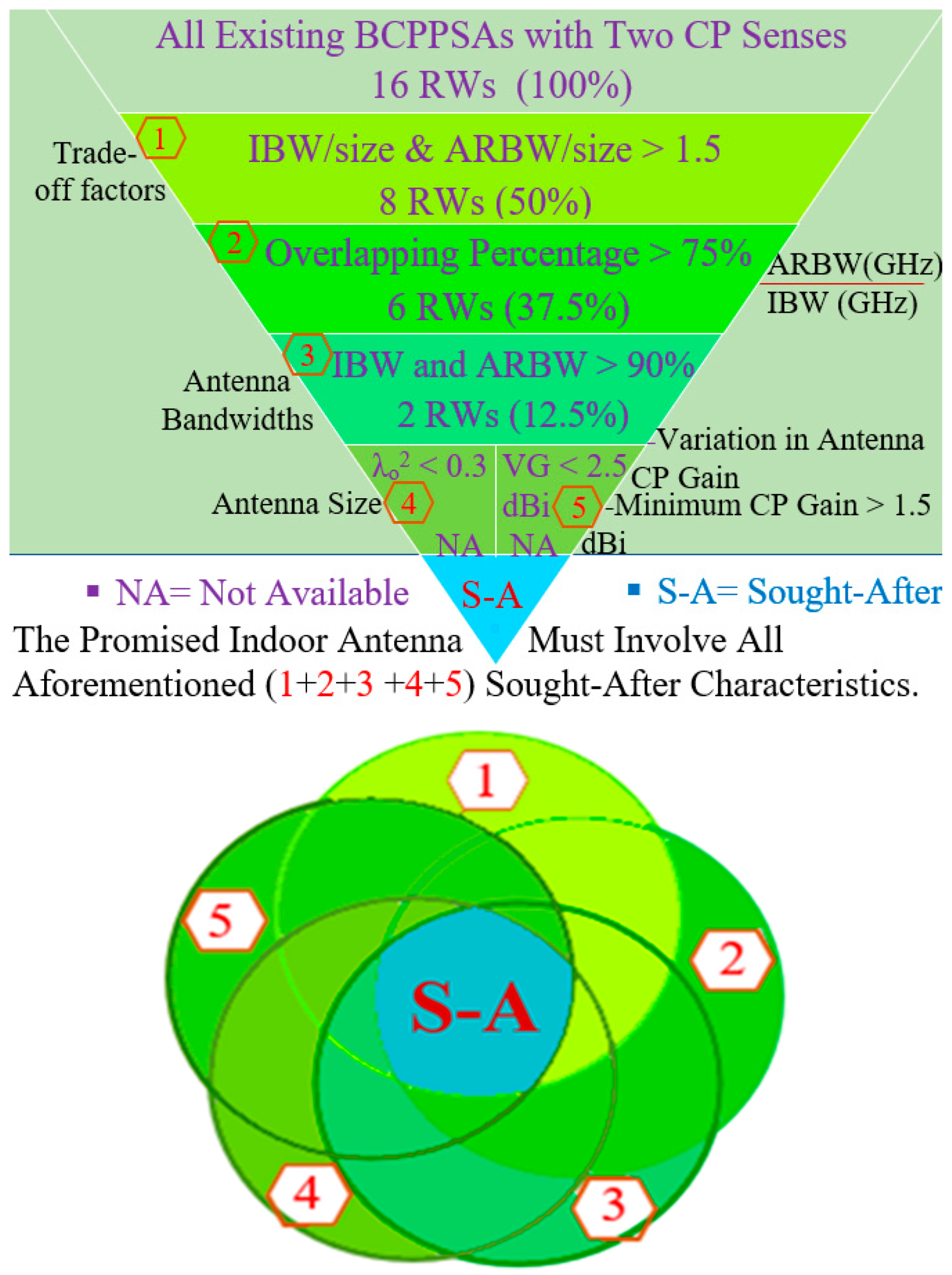
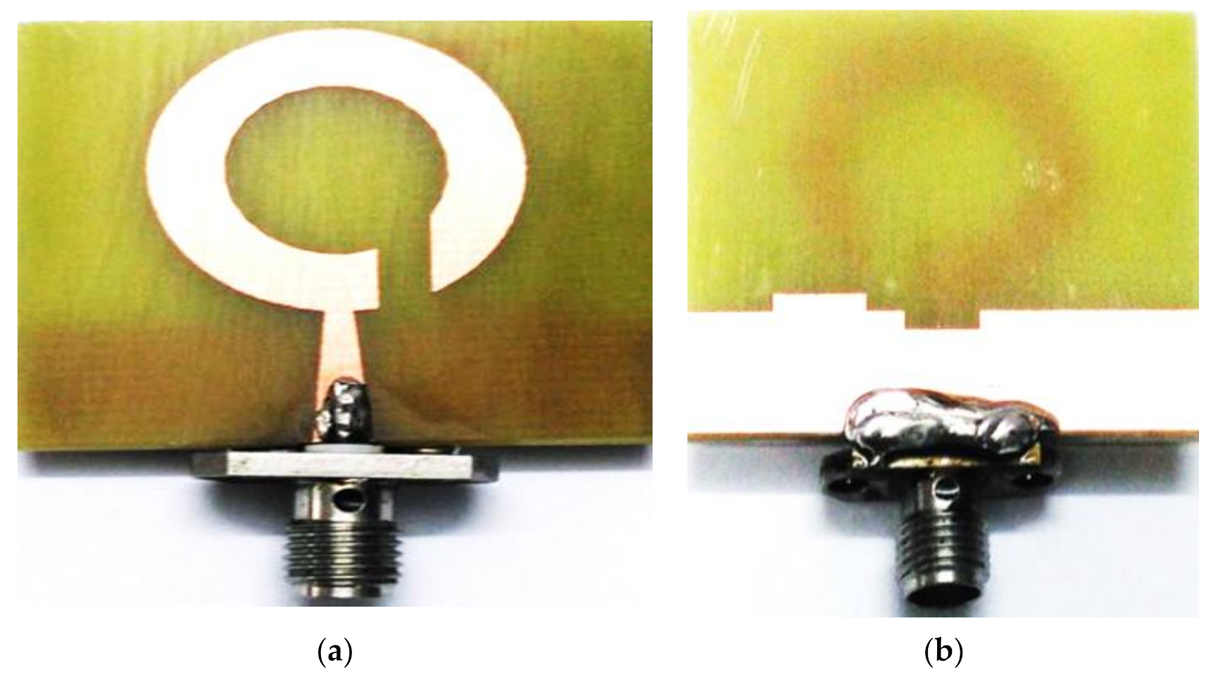
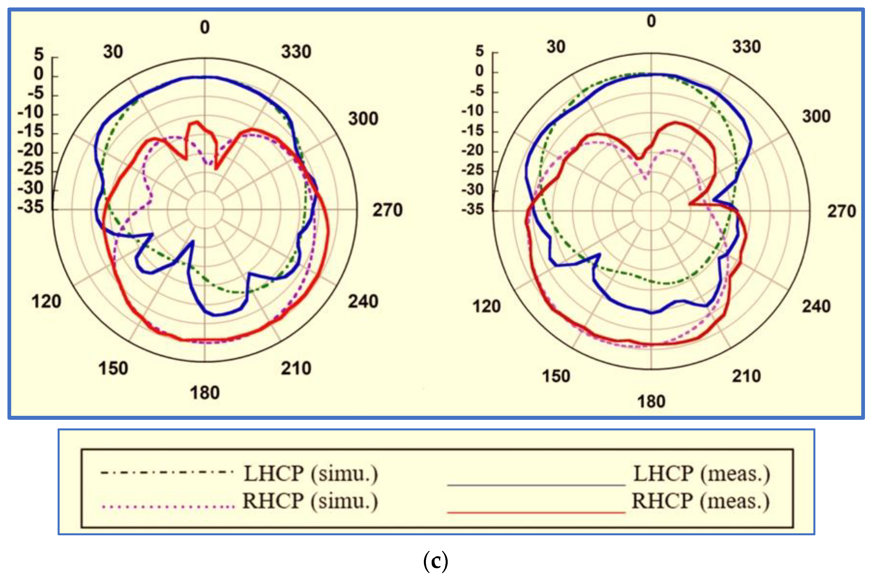
4.1. Broadband CP Printed Slot Antennas (BCPPSAs)
| # | Ref | fc (GHz) | IB-W (%) | AR-BW (%) | Gain (dB), (dBi), (dBic) | Size (mm2), λo2 | IBW/Size | ARBW/Size | OL% |
|---|---|---|---|---|---|---|---|---|---|
| 1 | [74] | 2.84 | 64 | 48.3 | 2.5–3.9 dB | 60 × 50, 0.27 | 2.37 | 1.79 | 77 |
| 2 | [85] | 5.82 | 84 | 41 | 3–3.5 dBi | 28 × 28, 0.3 | 2.8 | 1.37 | 48 |
| 3 | [86] | 6.375 | 90.2 | 40 | 0.8–4.5 dBi | 25 × 25, 0.28 | 3.2 | 1.43 | 40 |
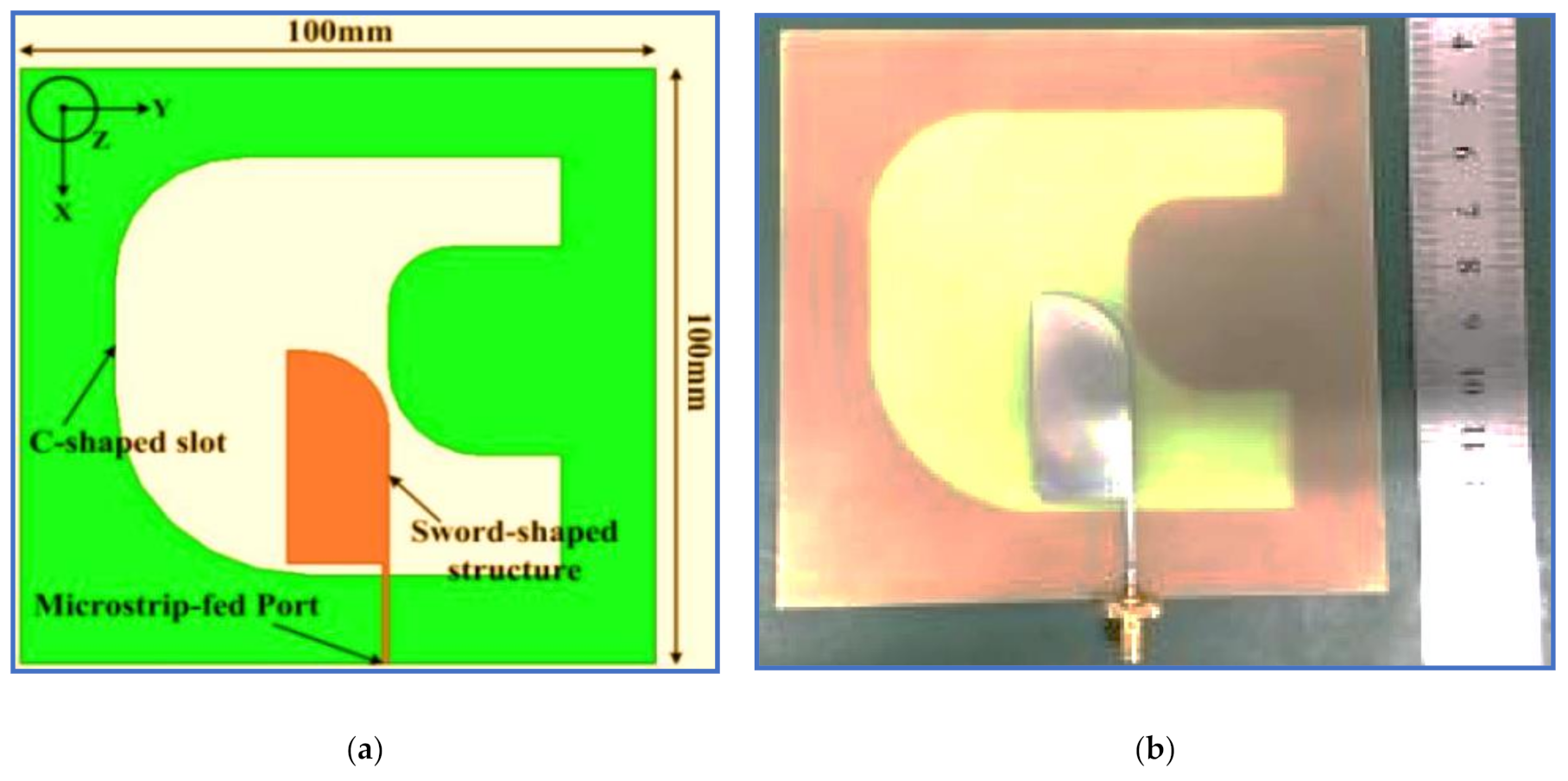
| 4 | [87] | 2.5 | 132 | 95.7 | 3–4.7 dBi | 100 × 100, 0.69 | 1.9 | 1.38 | 67 |
| 5 | [89] | 5.1 | 70.7 | 37.1 | 1.7–3.8 dBi | 30 × 30, 0.26 | 2.72 | 1.43 | 56 |
| 6 | [90] | 5.2 | 62 | 49 | 2–3.7 dB | 27 × 28.8, 0.23 | 2.63 | 2.13 | 72 |
| 7 | [91] | 5.15 | 92.6 | 83.5 | 2–5 dBi | 30 × 30, 0.27 | 3.43 | 3.09 | 84 |
| 8 | [96] | 4.5 | 104 | 91 | 1–3.2 dBi | 42 × 42, 0.4 | 2.62 | 2.27 | 76 |
| 9 | [97] | 8.6 | 125 | 61 | 4–4.3 dBi | 25 × 25, 0.51 | 2.45 | 1.2 | 26 |
| 10 | [99] | 9.6 | 92.7 | 54.2 | 2–4.5 dBi | 40 × 40, 1.6 | 0.56 | 0.34 | 48 |
| 11 | [18] | 4.3 | 100 | 108 | 2.3–5.5 dB | 45 × 43.6, 0.4 | 2.5 | 2.7 | 86 |
| 12 | [102] | 3.52 | 72 | 65 | 2–6.3 dBic | 37 × 39, 0.2 | 3.6 | 3.25 | 93 |
| 13 | [103] | 4.5 | 84.1 | 68.7 | 1.8–4 dBi | 30 × 30, 0.2 | 4.2 | 3.4 | 85 |
| 14 | [104] | 1.71 | 63.2 | 36.8 | 0.3–3.2 dBi | 60 × 60, 0.34 | 1.86 | 1.1 | 65 |
| 15 | [105] | 4.91 | 106 | 89 | 1.9–5.2 dBi | 40 × 45, 0.48 | 2.2 | 1.85 | 70 |
| 16 | [106] | 5.7 | 117 | 59 | 1– 3.2 dB | 38 × 38, 0.52 | 2.25 | 1.13 | 41 |
| Ref | Material | Radiator Shape | Technique to Broaden IBW | Technique to Generate the CP Property |
|---|---|---|---|---|
| [74] | FR4 | Asymmetric L-shaped | Decreasing and increasing the vertical and horizontal arms of the L-shaped radiator, respectively | Placing a rectangular parasitic patch above the L-shaped radiator and surrounding the exterior borders of the patch with a rectangular strip |
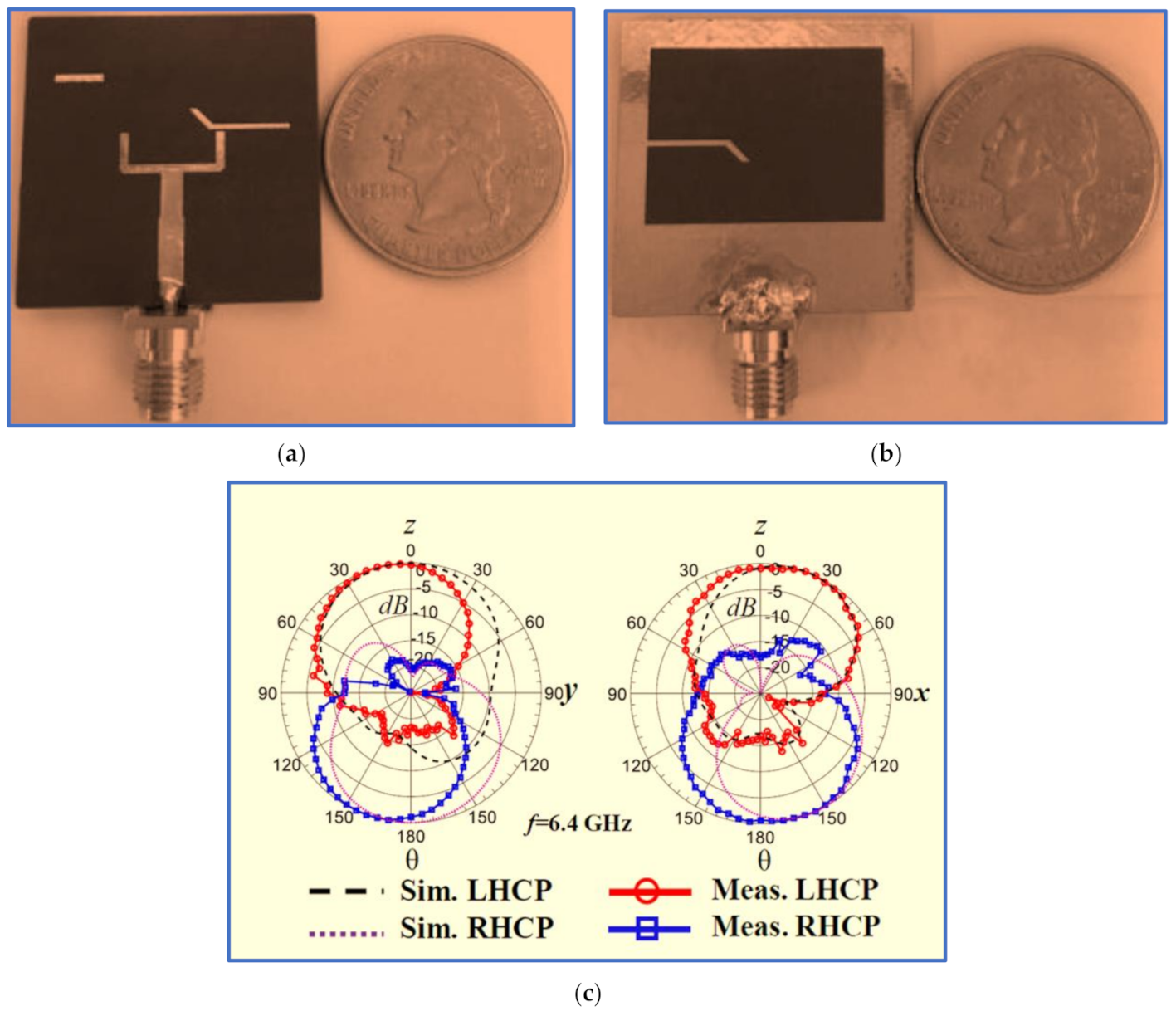
| [85] | Roger RT/5880 | U-shaped | Connecting the Y-shaped strip to the square slot ground | Employing half of the Y-shaped radiator and small strips as a parasitic strip |
| [86] | FR4 | Sword-shaped patch | Chamfering the two left corners of the radiator patch | Placing two arc-shaped stubs on the left corners of the ground plane slot |
| [87] | FR4 | Straight with vertical stub | Shifting the feed line to the right of the rectangular slot | Connecting the horizontal stub to the rectangular slot and shifting the feed line |
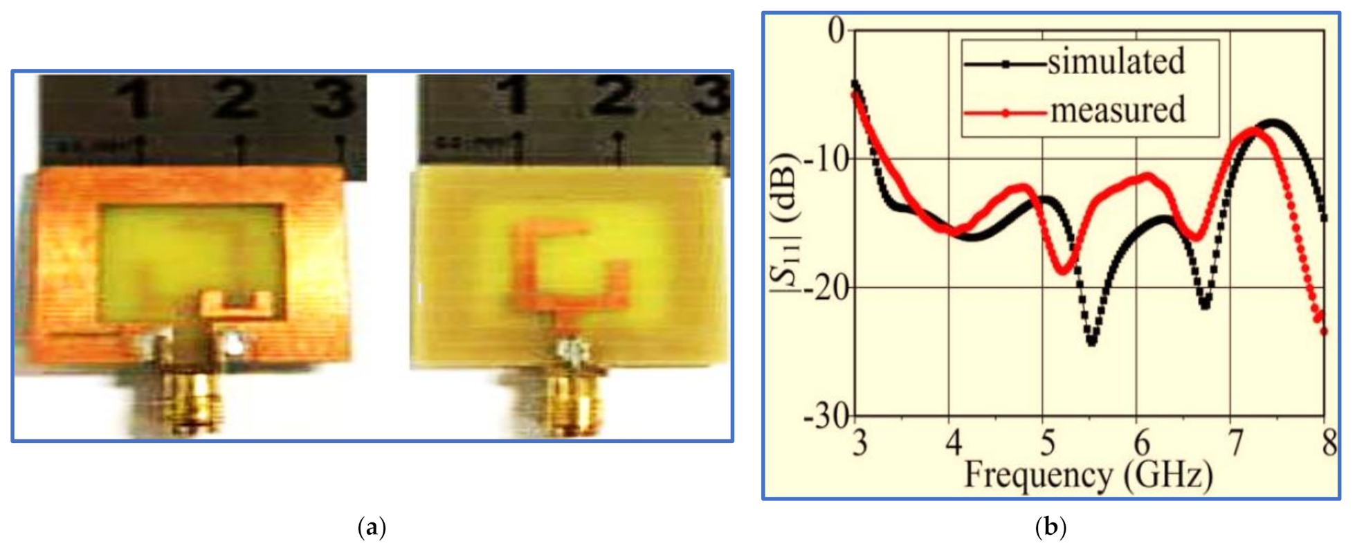
| [89] | FR4 | G-shaped patch | Inserting an L-shaped slot in the lower part of the ground plane slot | Introducing a U-shaped parasitic strip into the square slot |
| [90] | Arlon AD250C | Straight | Introducing a simple horizontal strip into the slot ground plane |
|
| [91] | FR4 | F-shaped | Inserting an inverted L-shaped slot in the lower border of the ground plane slot | Attaching two horizontal stubs to the feed line |
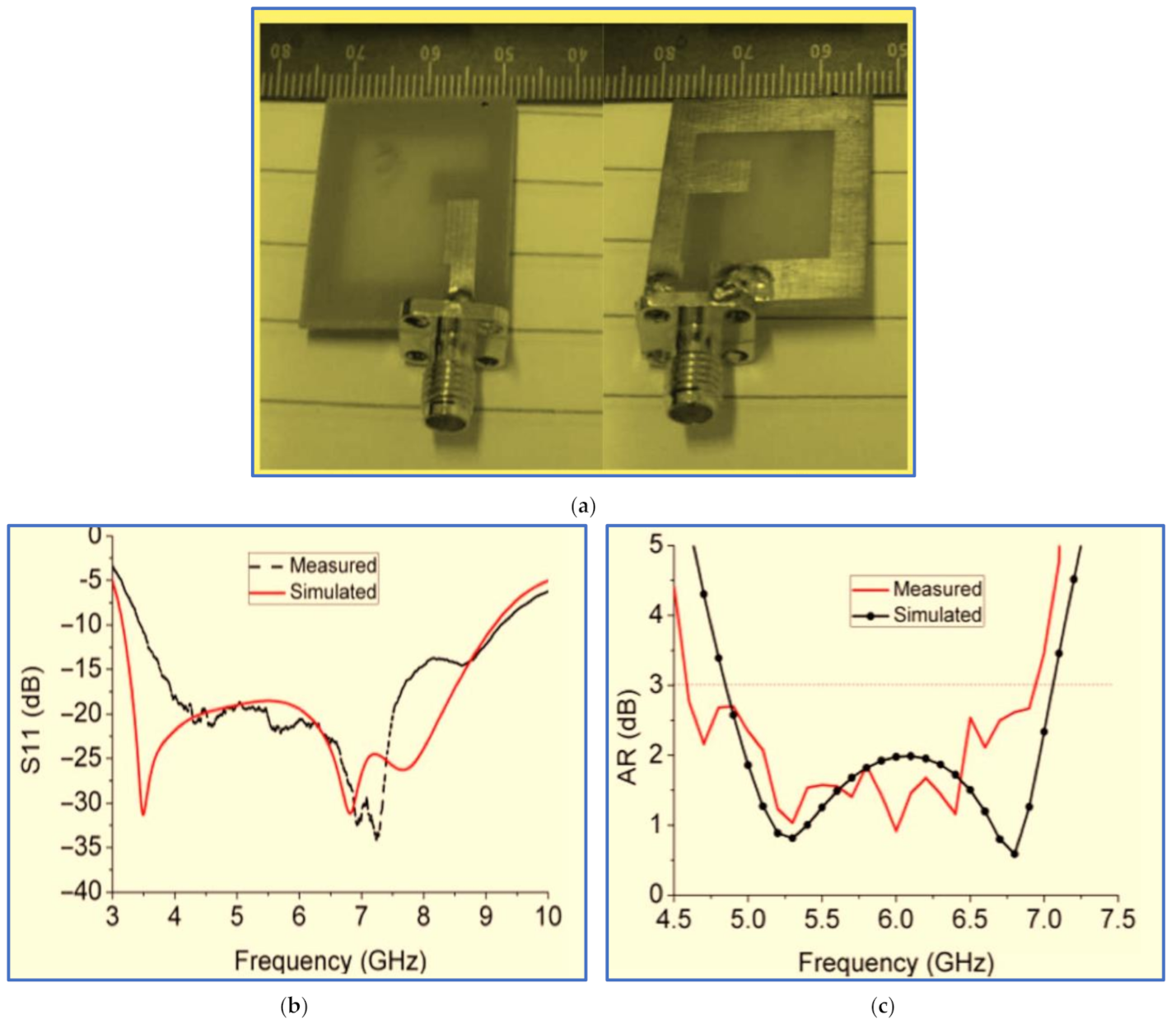
| [96] | Taconic RF-35 | C-shaped | Using an optimised C-shaped radiator | Etching a C-shaped slot in the ground plane |
| [97] | FR4 | Inverted L-shaped |
|
|
| [24] | Arlon AD250C | Straight feed line |
|
|
| [18] | FR4 | Straight feed line | Etching three linked slots in the ground plane patch |
|
| [103] | FR4 | Modified straight feed line | Modifying the feed line by attaching an L-shaped strip and a rectangular slot in the lower part of the feed line | Adding a cross-shaped parasitic strip in the middle of the ground slot |
| [104] | FR4-epoxy | Asymmetric Y-shaped | Attaching a vertical rectangular stub to the right side of the feed line | Connecting two inverted L-shaped strips to the two corners of a ground plane slot in diagonal directions and modifying the borders of the ground plane slot |
| [105] | FR4 | Modified L-shaped patch | Embedding a meandered arc-shaped slot into the radiator patch |
|
| [106] | Taconic RF-35 | Semi-circular patch | Using a conventional semi-circular radiator | Etching a full circular slot in the ground plane |
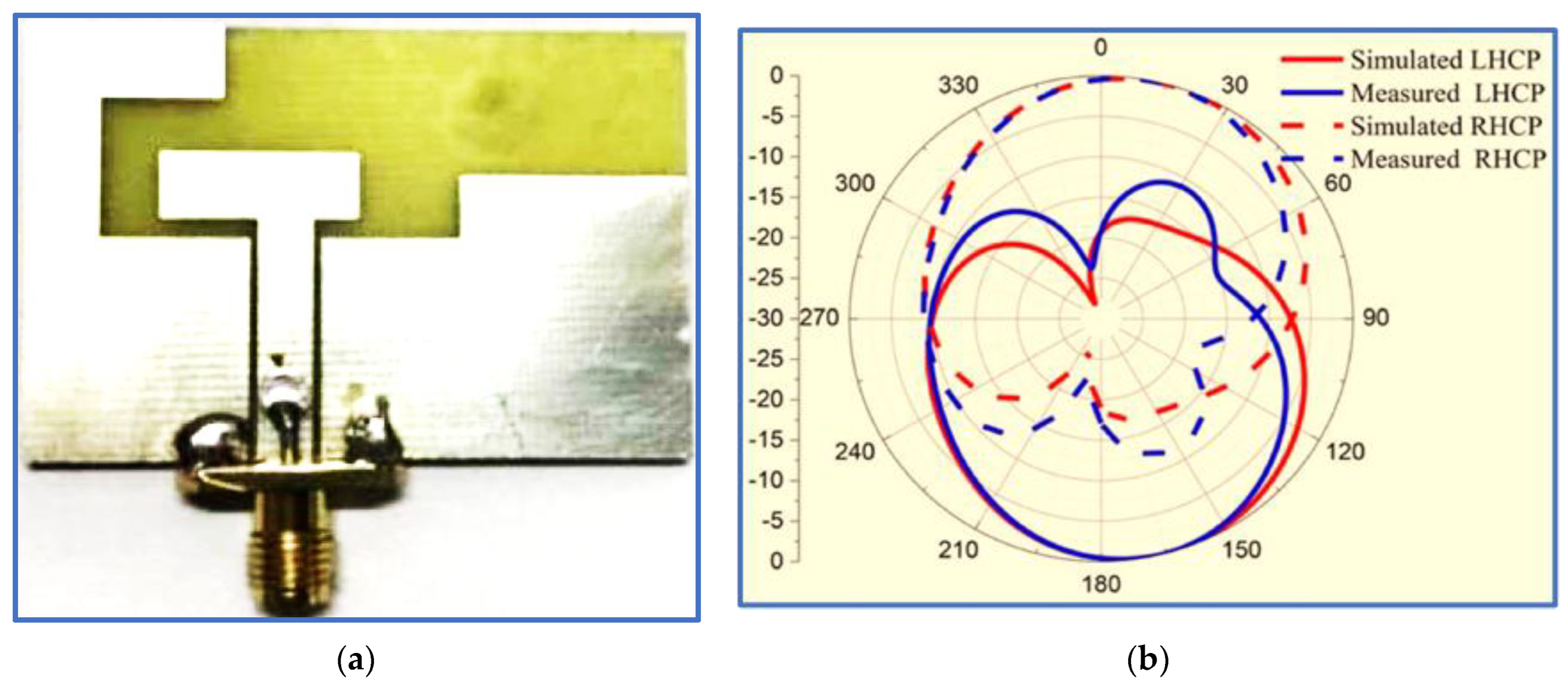
4.2. Broadband CP Printed Monopole Antennas (BCPPMAs)
| # | Material | Radiator Shape | Technique to Broaden IBW | Technique to Generate the CP Property |
|---|---|---|---|---|
| [96] | FR4 | Modified C-shaped | Adding two asymmetric triangular stubs above the ground plane | Extending the lower and upper edges of the C-shaped radiator and inserting a small slit in the radiator |
| [127] | FR4 | Rectangular | Coupling the radiator with the square ring-shaped patch using a parasitic strip | Applying asymmetric CPW ground plans |
| [128] | FR4 | Straight monopole | Placing an inverted L-shaped strip on the ground plane | Embedding a horizontal slit into the right CPW ground |
| [134] | FR4 | Modified rectangular | Embedding a vertical slot into the ground plane located under the feed line | Using the microstrip via method to achieve equilibrium between the vertical and horizontal components |
| [137] | FR4 | Monopole patch with perpendicular arms | Using an optimised meandering shaped Embedding a linked X-shaped slot and rectangular slot in the ground plane |
|
| [138] | FR4 epoxy | Asymmetric inverted L-shaped feed line | Keeping an optimised gap between the feed line and the upper edge of the ground plane | Hook-shaped branch connected to the partial ground plane corner for the purpose of coupling capacitance |
| [139] | FR4 | Inverted rectangular C-shaped |
|
|
| [141] | FR4 | Modified inverted C-shaped | Forming the monopole radiator by combining circular and rectangular rings | Modifying the ground plane by placing a triangular stub on the left side of the ground plane |
| [142] | FR4 | Asymmetric-fed rectangular shaped | Employing an asymmetric-fed rectangular patch as the radiator patch and an edge-fed rectangular monopole |
|
| [143] | FR4 | Chifre-shaped | Using a quarter circular patch as the radiator | Transferring the feed line and radiator towards the right |
| [144] | FR4 | Straight monopole |
| Coupling the feed line by using two spiral parasitic strips |
| [145] | FR4 | Cross-shaped monopole |
| Extending the right side of the ground plane to support EVer and EHor. The vertical slot in this extension yields a 90° PD between EVer and EHor |
| [146] | FR4 | Coin-shaped | Inserting two linked slots in the radiator patch |
|
| [147] | FR4 | Straight monopole |
|
|
| [148] | FR4 | Quasi C-shaped | Employing impedance transformation and a quasi C-shaped patch |
|
| # | Ref | fc (GHz) | IB-W (%) | AR-BW (%) | Gain (dB), (dBi), (dBic) | Size (mm2), λo2 | IBW/Size | ARBW/Size | OL% |
|---|---|---|---|---|---|---|---|---|---|
| 1 | [123] | 4.3 | 106 | 104 | 2–6 dBic | 49 × 55, 0.55 | 1.9 | 1.9 | 88 |
| 2 | [127] | 2.9 | 96.5 | 93 | 0.5–3.5 dBi | 50 × 55, 0.25 | 3.86 | 2.5 | 69 |
| 3 | [128] | 4.1 | 94 | 77 | 0.5–4 dB | 50 × 48, 0.44 | 2.13 | 1.75 | 72 |
| 4 | [134] | 6.8 | 59 | 48 | 1.8–3.4 dB | 25 × 24, 0.31 | 1.9 | 1.55 | 85 |
| 5 | [137] | 4.9 | 102 | 37.5 | 2–2.5 dB | 32 × 39, 0.33 | 3 | 1.14 | 40 |
| 6 | [138] | 3.48 | 56 | 63.6 | 2–3.7 dBic | 44 × 44, 0.26 | 2.15 | 2.4 | 79 |
| 7 | [139] | 5.72 | 62.9 | 53.9 | 2.5–3.5 dB | 32 × 30, 0.35 | 1.8 | 1.54 | 87 |
| 8 | [141] | 8.4 | 95.2 | 96.8 | 3–6.3 dBi | 25 × 25, 0.49 | 1.94 | 1.97 | 96 |
| 9 | [142] | 4.65 | 88.9 | 66.7 | 3–4 dBic | 19.5 × 36, 0.19 | 4.71 | 3.51 | 77.5 |
| 10 | [149] | 2.9 | 50 | 49 | 2–2.5 dBic | 46.6 × 70, 0.32 | 1.56 | 1.53 | 89 |
| 11 | [143] | 2.4 | 72 | 41.6 | 2.5–3.6 dBi | 58.4 × 63, 0.48 | 1.48 | 0.87 | 58 |
| 12 | [144] | 3.4 | 88 | 64.7 | 0.5–2.5 dBic | 55 × 50, 0.35 | 2.51 | 1.8 | 80 |
| 13 | [145] | 6 | 55.5 | 42.6 | 0.4–2.7 dBi | 16 × 22, 0.14 | 3.96 | 3 | 77 |
| 14 | [146] | 5.8 | 89.2 | 71 | 3.5–4 dBi | 50 × 50, 0.93 | 0.96 | 0.76 | 78 |
| 15 | [147] | 4.65 | 87.2 | 83.9 | 1–2.3 dBi | 55 × 55, 0.72 | 1.21 | 1.16 | 92 |
5. Conclusions
Author Contributions
Funding
Data Availability Statement
Conflicts of Interest
References
- Alejandro, A.Z. Indoor Wireless Communications: From Theory to Implementation, 1st ed.; Wiley: New York, NY, USA, 2017. [Google Scholar]
- Liu, C.-K.; Chiang, W.-Y.; Rao, P.-Z.; Hung, P.-H.; Chen, S.-H.; Chen, C.-A.; Wang, L.-H.; Abu, P.A.R.; Chen, S.-L. The Uses of a Dual-Band Corrugated Circularly Polarized Horn Antenna for 5G Systems. Micromachines 2022, 13, 289. [Google Scholar] [CrossRef] [PubMed]
- Al-Gburi, A.J.A.; Zakaria, Z.; Palandoken, M.; Ibrahim, I.M.; Althuwayb, A.A.; Ahmad, S.; Al-Bawri, S.S. Super Compact UWB Monopole Antenna for Small IoT Devices. Comput. Mater. Contin. 2022, 73, 2785–2799. [Google Scholar]
- Golmohamadi, M.; Narbudowicz, A.; Frolik, J. Mitigating Indoor Channels with Quad-Polarization Diversity. IEEE Antennas Wirel. Propag. Lett. 2019, 18, 1199–1202. [Google Scholar] [CrossRef]
- Stutzman, W.L. Polarization in Electromagnetic Systems, 2nd ed.; Artech House: London, UK, 2018. [Google Scholar]
- Banerjee, U.; Karmakar, A.; Saha, A. A review on circularly polarized antennas, trends and advances. Int. J. Microw. Wirel. Technol. 2020, 12, 922–943. [Google Scholar] [CrossRef]
- Ta, S.X.; Choo, H.; Park, I.; Ziolkowski, R.W. Multi-band, Wide-beam, Circularly Polarized, Crossed, Asymmetrically Barbed Dipole Antennas for GPS Applications. IEEE Trans. Antennas Propag. 2013, 61, 5771–5775. [Google Scholar] [CrossRef]
- Ullah, U.; Al-Hasan, M.; Koziel, S.; Mabrouk, I. Ben; Circular Polarization Diversity Implementation for Correlation Reduction in Wideband Low-Cost Multiple-Input-Multiple-Output Antenna. IEEE Access 2020, 8, 95585–95593. [Google Scholar] [CrossRef]
- Elbert, B.R. Introduction to Satellite Communications, 3rd ed.; Artech House: London, UK, 2009. [Google Scholar]
- Panahi, A.; Bao, X.L.; Ruvio, G.; Ammann, M.J. A Printed Triangular Monopole with Wideband Circular Polarization. IEEE Trans. Antennas Propag. 2015, 63, 415–418. [Google Scholar] [CrossRef]
- Xu, R.; Li, J.Y.; Liu, J. A Design of Broadband Circularly Polarized C-Shaped Slot Antenna with Sword-Shaped Radiator and Its Array for L/S-Band Applications. IEEE Access 2017, 6, 5891–5896. [Google Scholar] [CrossRef]
- Soliman, E.A.; De Raedt, W.; Vandenbosch, G.A.E. Reconfigurable slot antenna for polarization diversity. J. Electromagn. Waves Appl. 2009, 23, 905–916. [Google Scholar] [CrossRef]
- Wu, Q.; Ding, X.; Chen, A. A Broadband Dipole Antenna for Multiservice Indoor Distributed Antenna System (MS-IDAS). IEEE Antennas Wirel. Propag. Lett. 2015, 14, 839–842. [Google Scholar] [CrossRef]
- Huang, H.; Liu, Y.; Gong, S. Broadband Dual-Polarized Omnidirectional Antenna for 2G/3G/LTE/WiFi Applications. IEEE Antennas Wirel. Propag. Lett. 2016, 15, 576–579. [Google Scholar] [CrossRef]
- Hu, W.; Wu, J.J.; Tang, Z.Y.; Fei, P.; Yin, Y.Z. Single-Feed Wideband Circularly Polarized Crossed Dipole Antenna with Bent-Slot Loading. Electromagnetics 2017, 37, 162–170. [Google Scholar] [CrossRef]
- Zhai, H.; Yang, D.; Xi, L.; Feng, D. A New CPW-Fed Broadband Circularly Polarized Printed Monopole Antenna for UWB Application. Microw. Opt. Technol. Lett. 2018, 60, 364–369. [Google Scholar] [CrossRef]
- Jhajharia, T.; Tiwari, V.; Bhatnagar, D.; Yadav, D.; Rawat, S. A Dual-band CP Dual-orthogonal Arms Monopole Antenna with Slanting Edge DGS for C-band Wireless Applications. AEU–Int. J. Electron. Commun. 2018, 84, 251–257. [Google Scholar] [CrossRef]
- Huang, H.F.; Zhang, Z.P. A Small Single Fed Broadband Circularly Polarized Slot Antenna. Int. J. RF Microw. Comput.-Aided Eng. 2020, 30, e22122. [Google Scholar] [CrossRef]
- Saini, R.K.; Dwari, S.; Mandal, M.K.; Member, S. CPW-Fed Dual-Band Dual-Sense Circularly Polarized Monopole Antenna. IEEE Antennas Wirel. Propag. Lett. 2017, 16, 2497–2500. [Google Scholar] [CrossRef]
- Chaudhary, P.; Kumar, A. Compact Ultra-wideband Circularly Polarized CPW-fed Monopole Antenna. AEU–Int. J. Electron. Commun. 2019, 107, 137–145. [Google Scholar] [CrossRef]
- Yu, Q.; Liu, S.; Kong, X.; Qin, J.; Wen, Y.; Wang, L.; Xu, Y. Bandwidth Enhancement of a Circularly Polarized Tapered Crossed Slot Antenna with Corner Parasitic Directors. Int. J. RF Microw. Comput.-Aided Eng. 2020, 30, e22173. [Google Scholar] [CrossRef]
- Han, M.; Dou, W. Compact Clock-Shaped Broadband Circularly Polarized Antenna Based on Characteristic Mode Analysis. IEEE Access 2019, 7, 159952–159959. [Google Scholar] [CrossRef]
- Lu, Z.; Yang, L.; Yang, L. Design of a Broadband Circularly Polarized Antenna Array. Prog. Electromagn. Res. M 2019, 82, 195–203. [Google Scholar] [CrossRef]
- Ullah, U.; Koziel, S. A Novel Coplanar-Strip-Based Excitation Technique for Design of Broadband Circularly Polarization Antennas with Wide 3 dB Axial Ratio Beamwidth. IEEE Trans. Antennas Propag. 2019, 67, 4224–4229. [Google Scholar] [CrossRef]
- Rashmi; Kumar, A.; Saraswat, K.; Kumar, A. Wideband Circularly Polarized Parasitic Patches Loaded Coplanar Waveguide-fed Square Slot Antenna with Grounded Strips and Slots for Wireless Communication Systems. AEU–Int. J. Electron. Commun. 2020, 114, 3011–3019. [Google Scholar] [CrossRef]
- Cui, Y.; Li, R.L.; Wang, P. A Novel Broadband Planar Antenna for 2G/3G/LTE Base Stations. IEEE Trans. Antennas Propag. 2013, 61, 2767–2774. [Google Scholar] [CrossRef]
- Deng, C.; Li, Y.; Zhang, Z.; Feng, Z. Planar Printed Multi-Resonant Antenna for Octa-Band WWAN/LTE Mobile Handset. IEEE Antennas Wirel. Propag. Lett. 2015, 14, 1734–1737. [Google Scholar] [CrossRef]
- Ghouz, H.M.; Abo, M.F.; Ibrahim, M. Novel Wideband Microstrip Monopole Antenna Designs for WiFi/LTE/WiMax Devices. IEEE Access 2020, 8, 9532–9539. [Google Scholar] [CrossRef]
- Liu, G.; Zhang, J.; Zhang, P.; Wang, Y.; Liu, X.; Li, S. Evolution Map from TD-SCDMA to Future B3G TDD. IEEE Commun. Mag. 2006, 44, 54–61. [Google Scholar]
- Cui, Y.; Li, R.L.; Wang, P. Novel Dual-broadband Planar Antenna and its Array for 2G/3G/LTE Base Stations. IEEE Trans. Antennas Propag. 2013, 61, 1132–1139. [Google Scholar] [CrossRef]
- Wu, J.; Yang, S.; Chen, Y.; Qu, S.; Nie, Z. A Low Profile Dual-Polarized Wideband Omnidirectional Antenna Based on AMC Reflector. IEEE Trans. Antennas Propag. 2016, 65, 368–374. [Google Scholar] [CrossRef]
- Liu, Y.; Cui, W.; Jia, Y.; Ren, A. Hepta-Band Metal-Frame Antenna for LTE / WWAN. IEEE Antennas Wirel. Propag. Lett. 2020, 19, 1241–1245. [Google Scholar] [CrossRef]
- Hasan, M.M.; Faruque, M.R.I.; Islam, M.T. Dual Band Metamaterial Antenna for LTE/bluetooth/WiMAX System. Sci. Rep. 2018, 8, 1–17. [Google Scholar] [CrossRef]
- Yuan, X.T.; He, W.; Hong, K.D.; Han, C.Z.; Chen, Z.; Yuan, T. Ultra-wideband MIMO Antenna System with High Element-isolation for 5G Smartphone Application. IEEE Access 2020, 8, 56281–56289. [Google Scholar] [CrossRef]
- Wang, Z.; Dong, Y.; Itoh, T. Miniaturized Wideband CP Antenna Based on Meta-Resonator and CRLH-TLs for 5G New Radio Applications. IEEE Trans. Antennas Propag. 2020, 20, 168–175. [Google Scholar] [CrossRef]
- Cui, Y.; Wang, X.; Shen, G.; Li, R. A Tri-Band SIW-Cavity Backed Differentially Fed Dual-Polarized Slot Antenna for WiFi/5G Applications. IEEE Trans. Antennas Propag. 2020, 1, 2–7. [Google Scholar]
- Serghiou, D.; Khalily, M.; Singh, V.; Araghi, A.; Tafazolli, R. Sub-6 GHz Dual-Band 8x8 MIMO Antenna for 5G Smartphones. IEEE Antennas Wirel. Propag. Lett. 2020, 12, 7–12. [Google Scholar]
- Feng, B.; He, X.; Cheng, J.C.; Zeng, Q.; Sim, C.Y.D. A Low-Profile Differentially Fed Dual-Polarized Antenna with High Gain and Isolation for 5G Microcell Communications. IEEE Trans. Antennas Propag. 2020, 68, 90–99. [Google Scholar] [CrossRef]
- Soltani, S.; Lotfi, P.; Murch, R.D. A Port and Frequency Reconfigurable MIMO Slot Antenna for WLAN Applications. IEEE Trans. Antennas Propag. 2016, 64, 1209–1217. [Google Scholar] [CrossRef]
- Surendrakumar, P.; Mohan, B.C. A Triple-Frequency, Vertex-Fed Antenna for WLAN/WiMAX Applications. IEEE Antennas Propag. Mag. 2018, 60, 101–106. [Google Scholar] [CrossRef]
- Khan, M.S.; Iftikhar, A.; Shubair, R.M.; Capobianco, A.D.; Braaten, B.D.; Anagnostou, D.E. Eight-Element Compact UWB-MIMO/Diversity Antenna with WLAN Band Rejection for 3G/4G/5G Communications. IEEE Open J. Antennas Propag. 2020, 1, 196–206. [Google Scholar] [CrossRef]
- Javanbakht, N.; Amaya, R.E.; Shaker, J.; Syrett, B. A tapered CPW fed leaky-wave antenna based on substrate integrated waveguide with reduced side-lobe level. Int. J. RF Microw. Comput.-Aided Eng. 2021, 31, e22607. [Google Scholar] [CrossRef]
- Hirose, K.; Nakamura, K.; Nakano, H. Bent and branched microstrip-line antennas for circular polarization. J. Appl. Sci. 2022, 12, 1711. [Google Scholar] [CrossRef]
- Al-Gburi, A.J.A.; Ibrahim, I.M.; Zakaria, Z.; Abdulhameed, M.K.; Saeidi, T. Enhancing Gain for UWB Antennas Using FSS: A Systematic Review. Mathematics 2021, 9, 3301. [Google Scholar] [CrossRef]
- He, K.; Gong, S.X.; Guo, D. Broadband Omnidirectional Distributed Antenna for Indoor Wireless Communication Systems. Electron. Lett. 2016, 52, 1361–1362. [Google Scholar] [CrossRef]
- Yu, L.; Song, J.; Gao, Y.; He, K.; Gao, F. Low-profile Dual-polarized Omnidirectional Antenna for Broadband Indoor Distributed Antenna System. Prog. Electromagn. Res. Lett. 2017, 67, 39–45. [Google Scholar] [CrossRef][Green Version]
- Dai, X.W.; Mao, S.W.; Zhou, T. Broadband Circular Patch Antenna with Monopolar Radiation Pattern for Indoor Wireless Communication. Int. J. Microw. Wirel. Technol. 2017, 9, 953–958. [Google Scholar] [CrossRef]
- Bai, X.; Su, M.; Gao, Z.; Liu, Y. Broadband Dual-polarized Omnidirectional Antenna Based on Magnetic Dipoles. IEICE Electron. Express 2018, 15, 1149–1153. [Google Scholar] [CrossRef]
- Hong, W.; Sarabandi, K. Low Profile, Multi-element, Miniaturized Monopole Antenna. IEEE Trans. Antennas Propag. 2009, 57, 72–80. [Google Scholar] [CrossRef]
- Wu, F.; Luk, K.M. A Compact and Reconfigurable Circularly Polarized Complementary Antenna. IEEE Antennas Wirel. Propag. Lett. 2017, 16, 1188–1191. [Google Scholar] [CrossRef]
- Tran, H.H.; Park, I. A Dual-Wideband Circularly Polarized Antenna Using an Artificial Magnetic Conductor. IEEE Antennas Wirel. Propag. Lett. 2016, 15, 950–953. [Google Scholar] [CrossRef]
- Feng, G.; Chen, L.; Wang, X.; Xue, X.; Shi, X. Broadband Circularly Polarized Crossed Bowtie Dipole Antenna Loaded with Parasitic Elements. IEEE Antennas Wirel. Propag. Lett. 2018, 17, 114–117. [Google Scholar] [CrossRef]
- Liang, X.; Ren, J.; Zhang, L.; He, C.; Geng, J.; Zhu, W.; Jin, R. Wideband Circularly Polarized Antenna with Dual-Mode Operation. IEEE Antennas Wirel. Propag. Lett. 2019, 18, 767–770. [Google Scholar] [CrossRef]
- Li, G.; Zhang, F.S. A Compact Broadband and Wide Beam Circularly Polarized Antenna with Shorted Vertical Plates. IEEE Access 2019, 7, 90916–90921. [Google Scholar] [CrossRef]
- Xiao, M.; Liu, H.; Cui, Y. Broadband Circularly Polarized Antennas with Improved Gain. Appl. Comput. Electromagn. Soc. J. 2019, 37, 1514–1519. [Google Scholar]
- Ta, S.X. Broadband Dual-polarized Omnidirectional Antenna with Simple Feeding Structure. Int. J. RF Microw. Comput.-Aided Eng. 2020, 30, e22213. [Google Scholar] [CrossRef]
- Al-Gburi, A.J.A.; Ibrahim, I.M.; Zakaria, Z.; Ahmad, B.H.; Shairi, N.A.B.; Zeain, M.Y. High Gain of UWB Planar Antenna Utilising FSS Reflector for UWB Applications. Comput. Mater. Contin. 2022, 70, 1419–1436. [Google Scholar]
- Al-Gburi, A.J.A.; Ibrahim, I.M.; Zakaria, Z. An Ultra-Miniaturised MCPM Antenna for Ultra-Wideband Applications. J. Nano Electron. Phys. 2021, 13, 05012. [Google Scholar]
- Al-Gburi, A.J.A.; Ibrahim, I.M.; Zakaria, Z.; Khaleel, A.D. Bandwidth and Gain Enhancement of Ultra-Wideband Monopole Antenna Using MEBG Structure. J. Eng. Appl. Sci. 2019, 14, 3390–3393. [Google Scholar]
- Ellis, M.S.; Ahmed, A.R.; Kponyo, J.J.; Effah, F.B.; Nourinia, J.; Ghobadi, C.; Mohammadi, B. Compact Broadband Circularly Polarized Printed Antenna with a Shifted Monopole and Modified Ground Plane. J. Instrum. 2019, 14, 11026. [Google Scholar] [CrossRef]
- Kamaruddin, R.A.A.; Ibrahim, I.M.; Al-Gburi, A.J.A.; Zakaria, Z.; Shairi, N.A.; Rahman, T.A.; Purnamirza, T. Return Loss Improvement of Radial Line Slot Array Antennas on Closed Ring Resonator Structure at 28 GHz. Prz. Elektrotech. 2021, 5, 65–69. [Google Scholar] [CrossRef]
- Ahmad, S.; Manzoor, B.; Paracha, K.N.; Haider, S.; Liaqat, M.; Al-Gburi, A.J.A.; Ghaffar, A.; Alibakhshikenari, M.; Dalarsson, M. Wideband Bear-Shaped Compact Size Implantable Antenna for In-Body Communications. Appl. Sci. 2022, 12, 2859. [Google Scholar] [CrossRef]
- Abdulhameed, M.K.; Kod, M.S.; Al-gburi, A.J.A. Enhancement of Elevation Angle for an Array Leaky-Wave Antenna. Prz. Elektrotech. 2021, 8, 109–113. [Google Scholar] [CrossRef]
- Abdulhameed, M.K.; Hashim, S.R.; Abdalhameed, N.K.; Al-gburi, A.J.A. Increasing Radiation Power in Half Width Microstrip Leaky Wave Antenna by using Slots Technique. Int. J. Electr. Comput. Eng. 2022, 12, 392–398. [Google Scholar] [CrossRef]
- MoradiKordalivand, A.; Rahman, T.A.; Khalily, M. Common Elements Wideband MIMO Antenna System for WiFi/LTE Access-Point Applications. IEEE Antennas Wirel. Propag. Lett. 2014, 13, 1601–1604. [Google Scholar] [CrossRef]
- Al-Gburi, A.J.A.; Ibrahim, I.M.; Zakaria, Z.; Nazli, N.F.M. Wideband Microstrip Patch Antenna for Sub 6 GHz and 5G Applications. Prz. Elektrotech. 2021, 11, 26–29. [Google Scholar] [CrossRef]
- Al-Gburi, A.J.A.; Zakaria, Z.; Ibrahim, I.M.; Halim, E. Microstrip Patch Antenna Arrays Design for 5G Wireless Backhaul Application at 3. 5 GHz. Recent Adv. Electr. Electron. Eng. 2022, 865, 77–88. [Google Scholar]
- Qi, Y.; Yuan, B.; Cao, Y.; Wang, G. An Ultrawideband Low-Profile High-Efficiency Indoor Antenna. IEEE Antennas Wirel. Propag. Lett. 2020, 19, 346–349. [Google Scholar] [CrossRef]
- IEEE Std 145-1993; IEEE Standard Definitions of Terms for Antennas. Antenna Standards Committee of the IEEE Antennas and Propagation Society: New York, NY, USA, 1993.
- Balanis, C.A. Antenna Theory Analysis and Design, 4th ed.; Wiley: New York, NY, USA, 2016. [Google Scholar]
- Chourasia, S.; Sharma, S.K.; Goswami, P. Review on Miniaturization Techniques of Microstrip Patch Antenna. In Proceedings of the 4th International Conference ICEAST, Rajasthan, India, 21–22 February 2020. [Google Scholar]
- Mira, F.; Artiga, X.; Llamas-Garro, A.I.; Vázquez-Gallego, F.; Velázquez-González, J.S. Circularly Polarized Dual-Band LoRa/GPS Antenna for a UAV-Assisted Hazardous Gas and Aerosol Sensor. Micromachines 2021, 12, 377. [Google Scholar] [CrossRef]
- Zhang, J.; Tao, S.; Yan, X.; Zhang, X.; Guo, J.; Wen, Z. Dual-Frequency Polarized Reconfigurable Terahertz Antenna Based on Graphene Metasurface and TOPAS. Micromachines 2021, 12, 1088. [Google Scholar] [CrossRef]
- Saini, R.; Dwari, S. CPW-fed Broadband Circularly Polarized Rectangular Slot Antenna with L-Shaped Feed Line and Parasitic Elements. Microw. Opt. Technol. Lett. 2015, 57, 1788–1795. [Google Scholar] [CrossRef]
- Prakash, K.C.; Vinesh, P.V.; Mani, V.M.; Mathew, S.; Mohanan, P.; Vasudevan, K. Printed Circularly Polarised Asymmetric Ultra-wideband Antenna. Prog. Electromagn. Res. M 2018, 74, 179–189. [Google Scholar] [CrossRef]
- Kumar, Y.; Gangwar, R.K.; Kanaujia, B.K. Compact Broadband Circularly Polarized Hook-shaped Microstrip Antenna with DGS Plane. Int. J. RF Microw. Comput.-Aided Eng. 2018, 28, e21275. [Google Scholar] [CrossRef]
- Trinh-Van, S.; Yang, Y.; Lee, K.Y.; Hwang, K.C. Broadband Circularly Polarized Slot Antenna Loaded by a Multiple-Circular-Sector Patch. Sensors 2018, 18, 1576. [Google Scholar] [CrossRef] [PubMed]
- Ullah, U.; Koziel, S.; Mabrouk, I.B. Rapid Redesign and bandwidth/size Tradeoffs for Compact Wideband Circular Polarization Antennas Using Inverse Surrogates and fast EM-based Parameter Tuning. IEEE Trans. Antennas Propag. 2020, 68, 81–89. [Google Scholar] [CrossRef]
- Govindarajan, H.; Pavone, S.C.; Di Donato, L.; Di Mariano, P.; Distefano, G.; Livreri, P.; Nagaradjane, P.; Squadrito, C.; Sorbello, G. Design of a Compact Dual Circular-Polarized Antenna for L-Band Satellite Applications. IEEE Antennas Wirel. Propag. Lett. 2020, 19, 547–551. [Google Scholar] [CrossRef]
- Priya, S.; Kumar, K.; Dwari, S.; Mandal, M.K. Circularly Polarized Self-Diplexing SIW Cavity Backed Slot Antennas. IEEE Trans. Antennas Propag. 2020, 68, 2387–2392. [Google Scholar] [CrossRef]
- Gorai, A.; Roy, B.; Mahanti, G.K. A Compact CPW-fed Wideband Slot Antenna with Reflector for Wireless Communication. Electromagnetics 2019, 39, 556–570. [Google Scholar] [CrossRef]
- Patil, S.; Singh, A.K.; Kanaujia, B.K.; Yadava, R.L. A Low-profile Triple-band Circularly Polarized Wide Slot Antenna for Wireless Systems. Int. J. Microw. Wirel. Technol. 2019, 11, 53–66. [Google Scholar] [CrossRef]
- Xu, Y.; Wang, Z.; Dong, Y. Circularly Polarized Slot Antennas with Dual-Mode Elliptic Cavity. IEEE Antennas Wirel. Propag. Lett. 2020, 19, 715–719. [Google Scholar] [CrossRef]
- Jiang, L.; Lu, C.; Cao, W.; Sun, L. A Broadband CPW-fed Dual Circularly Polarized Slot Antenna with Modified L-shaped Monopoles. IEICE Electron. Express 2018, 15, 20180645. [Google Scholar] [CrossRef]
- Nosrati, M.; Tavassolian, N. Miniaturized Circularly Polarized Square Slot Antenna with Enhanced Axial-Ratio Bandwidth Using an Antipodal Y-strip. IEEE Antennas Wirel. Propag. Lett. 2017, 16, 817–820. [Google Scholar] [CrossRef]
- Xu, R.; Li, J.Y.; Yang, J.J.; Wei, K.; Qi, Y.-X. A Design of u-shaped Slot Antenna with Broadband Dual Circularly Polarized Radiation. IEEE Trans. Antennas Propag. 2017, 65, 3217–3220. [Google Scholar] [CrossRef]
- Ellis, M.S.; Zhao, Z.; Wu, J.; Ding, X.; Nie, Z.; Liu, Q.H. A Novel Simple and Compact Microstrip-Fed Circularly Polarized Wide Slot Antenna with Wide Axial Ratio Bandwidth for C-Band Applications. IEEE Trans. Antennas Propag. 2016, 64, 1552–1555. [Google Scholar] [CrossRef]
- Parchin, N.; Basherlou, H.J.; Abd-Alhameed, R.A. Dual Circularly Polarized Crescent-Shaped Slot Antenna for 5G Front-End Systems. Prog. Electromagn. Res. Lett. 2020, 91, 41–48. [Google Scholar] [CrossRef]
- Kwame, O.G.; Huang, Y.; Wen, G.; Li, J. Broadband Circularly Polarized Square Slot Antenna with a G-shaped Feedline. Microw. Opt. Technol. Lett. 2017, 12, 3055–3063. [Google Scholar]
- Ullah, U.; Koziel, S. A Broadband Circularly Polarized Wide-Slot Antenna with a Miniaturized Footprint. IEEE Antennas Wirel. Propag. Lett. 2018, 17, 2454–2458. [Google Scholar] [CrossRef]
- Gyasi, K.O.; Wen, G.; Inserra, D.; Affum, E.A.; Huang, Y.; Li, J.; Basit, M.A.; Zhang, H. A Compact Broadband Circularly Polarized Slot Antenna with Two Linked Rectangular Slots and an Inverted-F Feed Line. IEEE Trans. Antennas Propag. 2018, 66, 7374–7377. [Google Scholar] [CrossRef]
- Birwal, A.; Singh, S.; Kanaujia, B.K.; Kumar, S. Broadband CPW-fed Circularly Polarized Antenna for IoT-based Navigation System. Int. J. Microw. Wirel. Technol. 2019, 11, 835–843. [Google Scholar] [CrossRef]
- Kumar, V.; Khan, M.I.; Chandra, A.; Das, S. Broadband Circularly Polarized Planar Slot Antenna for Bluetooth/WiMAX Application. Adv. Comput. Commun. Control 2019, 14, 105–111. [Google Scholar]
- Paul, P.M.; Kandasamy, K.; Sharawi, M.S. A Corner Expanded Slot Antenna Loaded with Copper Strips for Dual-band Circular Polarization Characteristics. Microw. Opt. Technol. Lett 2020, 62, 491–497. [Google Scholar] [CrossRef]
- Srivastava, K.; Mishra, B.; Patel, A.K.; Singh, R. Circularly Polarized Defected Ground Stub-matched Triple-band Microstrip Antenna for C- and X-band Applications. Microw. Opt. Technol. Lett. 2020, 62, 3301–3309. [Google Scholar] [CrossRef]
- Tran, H.H.; Nguyen-Trong, N.; Abbosh, A.M. Simple Design Procedure of a Broadband Circularly Polarized Slot Monopole Antenna Assisted By Characteristic Mode Analysis. IEEE Access 2018, 6, 78386–78393. [Google Scholar] [CrossRef]
- Ellis, M.S.; Effah, F.B.; Ahmed, A.R.; Kponyo, J.J.; Nourinia, J.; Ghobadi, C.; Mohammadi, B. Asymmetric Circularly Polarized Open-slot Antenna. Int. J. RF Microw. Comput.-Aided Eng. 2020, 30, e22141. [Google Scholar] [CrossRef]
- Vadlamudi, R.; Kumar, D.S. Design of a Circular Slot Antenna with Broadband Dual CP Bi-directional Radiation Pattern. In Proceedings of the IEEE International Students’ Conference on Electrical, Electronics and Computer Science (SCEECS), Bhopal, India, 22–23 February 2020. [Google Scholar]
- Wang, L.; Fang, W.; En, Y.; Huang, Y.; Shao, W.; Yao, B. A New Broadband Circularly Polarized Square-Slot Antenna with Low Axial Ratios. Int. J. RF Microw. Comput.-Aided Eng. 2019, 29, e21502. [Google Scholar] [CrossRef]
- Jin, G.; Zeng, G.; Deng, C. A Broadband CPW-Fed Circularly Polarized Slot Antenna with F-shaped Feedline. In Proceedings of the IEEE, Sixth Asia-Pacific Conference on Antennas and Propagation (APCAP), Xi’an, China, 16–19 October 2017. [Google Scholar]
- Midya, M.; Bhattacharjee, S.; Mitra, M. Compact CPW-Fed Circularly Polarized Antenna for WLAN Application. Prog. Electromagn. Res. M 2018, 67, 65–73. [Google Scholar] [CrossRef]
- Ullah, U.; Koziel, S.; Mabrouk, I.B. A Simple Topology Compact Broadband Circularly Polarized Antenna with Unidirectional Radiation Pattern. IEEE Antennas Wirel. Propag. Lett. 2019, 18, 2612–2616. [Google Scholar] [CrossRef]
- Kwame, O.G.; Wen, G.; Huang, Y.; Ampoma, A.E.; Hu, W. Broadband Circularly Polarized Cross Shaped Slot Antenna with an Improved Feedline. Prog. Electromagn. Res. C 2017, 74, 141–149. [Google Scholar] [CrossRef][Green Version]
- Luo, K.; Chen, B.; Yi, Y.; Wang, Y. Miniaturised Design of Coplanar Waveguidefed Broadband Circularly Polarised Slot Antenna. IET Microw. Antennas Propag. 2015, 9, 1200–1204. [Google Scholar] [CrossRef]
- Li, T.; Zhang, F.S.; Gao, F.; Guo, Y.L. CPW-fed Circularly Polarized Square Slot Antenna with Enhanced Bandwidth and Reduced Size for Wideband Wireless Applications. Prog. Electromagn. Res. C 2016, 65, 121–129. [Google Scholar] [CrossRef]
- Le, T.T.; Hoang, V.; Park, H.C. Simple and Compact Slot-patch Antenna with Broadband Circularly Polarized Radiation. Microw. Opt. Technol. Lett. 2016, 58, 748–753. [Google Scholar]
- Ahmad, K.S.; Aziz, M.Z.A.A.; Abdullah, N.B. Microstrip Antenna Array with Defected Ground Structure and Copper Tracks for Bandwidth Enhancement. In Proceedings of the IEEE International RF and Microwave Conference (RFM 2020), Kuala Lumpur, Malaysia, 14–16 December 2020. [Google Scholar]
- Ahmad, K.S.; Aziz, M.Z.A.A.; Abdullah, N.B. A Dual-Band Frequency Reconfigurable Antenna Array Based on Reconfigurable Defected Ground Structure. In Proceedings of the IEEE International RF and Microwave Conference (RFM 2020), Kuala Lumpur, Malaysia, 14–16 December 2020. [Google Scholar]
- Al-Gburi, A.J.A.; Ibrahim, I.M.; Ahmad, K.S.; Abdulhameed, M.K.; Saeidi, T. A Miniaturised UWB FSS with Stop-Band Characteristics for EM Shielding Applications. Prz. Elektrotech. 2021, 1, 142–145. [Google Scholar] [CrossRef]
- Harish, A.R.; Sachidananda, M. Antennas and Wave Propagation, 1st ed.; Oxford University Press: Oxfordshire, UK, 2007. [Google Scholar]
- Chen, Z.N. Broadband Roll Monopole. IEEE Trans. Antennas Propag. 2003, 51, 3175–3177. [Google Scholar] [CrossRef]
- Wong, K.L.; Su, S.W.; Tang, C.L. Broadband Omnidirectional Metal-plate Monopole Antenna. IEEE Trans. Antennas Propag. 2005, 53, 581–583. [Google Scholar] [CrossRef]
- Chen, A.; Sun, M.; Zhang, Z.; Fu, X. Planar Monopole Antenna with a Parasitic Shorted Strip for Multistandard Handheld Terminals. IEEE Access 2020, 8, 51647–51652. [Google Scholar] [CrossRef]
- Mohamadzade, B.; Rezaee, A. Compact and Broadband Dual Sleeve Monopole Antenna for GSM, Wimax and WLAN Application. Microw. Opt. Technol. Lett. 2017, 59, 748–753. [Google Scholar] [CrossRef]
- Jou, C.F.; Wu, J.W.; Wang, C.J. Novel Broadband Monopole Antennas with Dual-band Circular Polarization. IEEE Trans. Antennas Propag. 2009, 57, 1027–1034. [Google Scholar] [CrossRef]
- Chen, B.; Jiao, Y.C.; Ren, F.C.; Zhang, L. Broadband Monopole Antenna with Wideband Circular Polarization. Prog. Electromagn. Res. Lett. 2012, 32, 19–28. [Google Scholar] [CrossRef]
- Midya, M.; Bhattacharjee, S.; Mitra, M. Circularly Polarized Planar Monopole Antenna for Ultrawideband Applications. Int. J. RF Microw. Comput.-Aided Eng. 2019, 29, e21918. [Google Scholar] [CrossRef]
- Ghobadi, A.; Dehmollaian, M. A Printed Circularly Polarized Y-Shaped Monopole Antenna. IEEE Antennas Wirel. Propag. Lett. 2012, 11, 22–25. [Google Scholar] [CrossRef]
- Thomas, K.G.; Praveen, G. A Novel Wideband Circularly Polarized Printed Antenna. IEEE Trans. Antennas Propag. 2012, 60, 5564–5570. [Google Scholar] [CrossRef]
- Hu, W.; Li, C.; Liu, X.; Wen, L.; Feng, T.; Jiang, W.; Gao, S. Wideband Circularly Polarized Microstrip Patch Antenna with Multimode Resonance. IEEE Antennas Wirel. Propag. Lett. 2021, 20, 533–537. [Google Scholar] [CrossRef]
- Komarudin, N.A.; Zakaria, Z.; Althuwayb, A.A.; Lago, H.; Alsariera, H.; Nornikman, H.; Al-Gburi, A.J.A.; Soh, P.J. Directional Wideband Wearable Antenna with Circular Parasitic Element for Microwave Imaging Applications. Comput. Mater. Contin. 2022, 72, 983–998. [Google Scholar] [CrossRef]
- Kumar, S.; Choudhary, V.S.; Andotra, A.; Chauhan, H.; Mathur, A. Circularly Polarized Microstrip Patch Antenna for 5G Applications. Inintell. Sustain. Syst. 2022, 334, 273–282. [Google Scholar]
- Tang, H.; Wang, K.; Wu, R.; Yu, C.; Zhang, J.; Wang, X. A Novel Broadband Circularly Polarized Monopole Antenna Based on C-Shaped Radiator. IEEE Antennas Wirel. Propag. Lett. 2016, 16, 964–967. [Google Scholar] [CrossRef]
- Yaozhou, Y.; Guirong, F.; Chen, L.; Hao, Y.; Rundong, X. Broadband Circularly Polarized Monopole Antenna with an Open loop. In Proceedings of the IEEE International Conference on Microwave and Millimeter Wave Technology (ICMMT), Chengdu, China, 1–3 May 2018. [Google Scholar]
- Dhara, R.; Mitra, M. A Triple-Band Circularly Polarized Annular Ring Antenna with Asymmetric Ground Plane for Wireless Applications. Eng. Rep. 2020, 2, e12150. [Google Scholar] [CrossRef]
- Sahal, M.; Tiwari, V.; Bhatnagar, D. Wideband CPW fed Circularly Polarized Antenna Using Planar Transmission Line DGS. In Proceedings of the IEEE, 7th International Conference on Signal Processing and Integrated Networks (SPIN), Noida, India, 27–28 February 2020. [Google Scholar]
- Ding, K.; Guo, Y.X.; Gao, C. CPW-Fed Wideband Circularly Polarized Printed Monopole Antenna with Open Loop and Asymmetric Ground Plane. IEEE Antennas Wirel. Propag. Lett. 2017, 16, 833–836. [Google Scholar] [CrossRef]
- Chen, Q.; Zhang, H.; Yang, L.C.; Xue, B.; Min, X.L. Broadband CPW-fed Circularly Polarized Planar Monopole Antenna with Inverted-L Strip and Asymmetric Ground Plane for WLAN Application. Prog. Electromagn. Res. C 2017, 74, 91–100. [Google Scholar] [CrossRef][Green Version]
- Arshad, S.; Tahir, F.A.; Rashid, A.; Missen, M.S.; Flint, J.A. Co-Planar-Waveguide Fed Circularly Polarized Antenna for Wireless WLAN / LTE Applications. Electromagnetics 2020, 40, 354–363. [Google Scholar] [CrossRef]
- Jan, J.Y.; Pan, C.Y.; Chiu, K.Y.; Chen, H.M. Broadband CPW-Fed Circularly Polarized Slot Antenna with an Open Slot. IEEE Trans. Antennas Propag. 2013, 61, 1418–1422. [Google Scholar] [CrossRef]
- Zhang, L.; Jiao, Y.C.; Ding, Y.; Chen, B.; Weng, Z.B. CPW-Fed Broadband Circularly Polarized Planar Monopole Antenna with Improved Ground-Plane Structure. IEEE Trans. Antennas Propag. 2013, 61, 4824–4828. [Google Scholar] [CrossRef]
- Banerjee, U.; Karmakar, A.; Saha, A.; Chakraborty, P. A CPW-fed Compact Monopole Antenna with Defected Ground Structure and Modified Parasitic Hilbert Strip Having Wideband Circular Polarization. AEU–Int. J. Electron. Commun. 2019, 110, 831–840. [Google Scholar] [CrossRef]
- Zhang, R.; Huang, J.; DIng, J.; Zhai, G. Compact Broadband Circularly Polarized Microstrip Antenna with A Cross-Slotted Ground Plane. In Proceedings of the IEEE International Symposium on Antennas and Propagation and USNC-URSI Radio Science Meeting (APSURSI), Atlanta, GA, USA, 7–12 July 2019. [Google Scholar]
- Chen, Q.; Zhang, H.; Yang, L.C.; Li, B.B.; Min, X.L. Wideband Inverted-L Microstrip-via-Fed Circularly Polarized Antenna with Asymmetrical Ground for WLAN/Wimax Applications. Frequenz 2017, 72, 333–341. [Google Scholar] [CrossRef]
- Islam, M.T.; Islam, M.T.; Samsuzzaman, M.; Rahman, M.; Singh, M.J.; Islam, M.T. Asymmetric Feed Circularly Polarized Broadband Printed Antenna for Wireless Communication. J. Optoelectron. Adv. M. 2020, 22, 129–135. [Google Scholar]
- Lv, C.Z.; Yang, L.C. Inverted-L Microstrip Open Slot Antenna with Wideband Circularly Polarization for Wimax Application. Int. J. Microw. Wirel. Technol. 2018, 10, 497–504. [Google Scholar] [CrossRef]
- Jhajharia, T.; Tiwari, V.; Yadav, D.; Rawat, S.; Bhatnagar, D. Wideband Circularly Polarised Antenna with an Asymmetric Meandered-shaped Monopole and Defected Ground Structure for Wireless Communication. IET Microw. Antennas Propag. 2018, 12, 1554–1558. [Google Scholar] [CrossRef]
- Samsuzzaman, M.; Islam, M.T.; Singh, M.J. A Compact Printed Monopole Antenna with Wideband Circular Polarization. IEEE Access 2018, 6, 54713–54725. [Google Scholar] [CrossRef]
- Midya, M.; Bhattacharjee, S.; Mitra, M. Broadband Circularly Polarized Planar Monopole Antenna with G-Shaped Parasitic Strip. IEEE Antennas Wirel. Propag. Lett. 2019, 18, 581–585. [Google Scholar] [CrossRef]
- Sam, K.U.; Abdulla, P. Truncated Circular Microstrip Ultra Wideband Antenna Exhibiting Wideband Circular Polarization. Prog. Electromagn. Res. C 2020, 99, 111–122. [Google Scholar] [CrossRef][Green Version]
- Li, Z.Y.; Zhu, X.S.; Yin, C.Y.; Huang, Y. A Broadband Circularly Polarized Monopole Antenna. Int. J. RF Microw. Comput.-Aided Eng. 2019, 29, e21687. [Google Scholar] [CrossRef]
- Ellis, M.S.; Ahmed, A.R.; Kponyo, J.J.; Nourinia, J.; Ghobadi, C.; Mohammadi, B. Simple Circularly Polarized Planar Monopole Inverted T-Shaped Antenna. Microw. Opt. Technol. Lett. 2019, 62, 405–410. [Google Scholar] [CrossRef]
- Han, R.C.; Zhong, S.S. Broadband Circularly Polarised Chifre-shaped Monopole Antenna with Asymmetric Feed. Electron. Lett. 2016, 52, 256–258. [Google Scholar] [CrossRef]
- Ding, K.; Gao, C.; Wu, Y.; Qu, D.; Zhang, B. A Broadband Circularly Polarized Printed Monopole Antenna with Parasitic Strips. IEEE Antennas Wirel. Propag. Lett. 2017, 16, 2509–2512. [Google Scholar] [CrossRef]
- Gyasi, K.O.; Wen, G.; Inserra, D.; Huang, Y.; Li, J.; Ampoma, A.E.; Zhang, H. A Compact Broadband Cross-Shaped Circularly Polarized Planar Monopole Antenna with a Ground Plane Extension. IEEE Antennas Wirel. Propag. Lett. 2018, 17, 335–338. [Google Scholar] [CrossRef]
- Chen, T.; Zhang, J.; Wang, W. A Novel CPW-Fed Planar Monopole Antenna with Broadband Circularly Polarization. Prog. Electromagn. Res. M 2019, 84, 11–20. [Google Scholar] [CrossRef]
- Feng, G.; Chen, L.; Shi, X. A Broadband Circularly Polarized Monopole Antenna Employing Parasitic Loops and Defective Ground Plane. Microw. Opt. Technol. Lett. 2020, 62, 251–256. [Google Scholar] [CrossRef]
- Ding, K.; Gao, C.; Yu, T.; Qu, D. Broadband C-shaped circularly polarized monopole antenna. IEEE Trans. Antennas Propag. 2014, 63, 785–790. [Google Scholar] [CrossRef]
- Hu, B.; Nasimuddin; Shen, Z. Broadband Circularly Polarized Moon-shaped Monopole Antenna. Microw. Opt. Technol. Lett. 2015, 50, 72–75. [Google Scholar] [CrossRef]
- Foudazi, A.; Hassani, H.R.; Ali Nezhad, S.M. Small UWB Planar Monopole Antenna with Added GPS/GSM/WLAN Bands. IEEE Trans. Antennas Propag. 2012, 60, 2987–2992. [Google Scholar] [CrossRef]
- Donelli, M.; Robol, F. Circularly Polarized Monopole Hook Antenna for ISM-band Systems. Microw. Opt. Technol. Lett. 2018, 60, 1452–1454. [Google Scholar] [CrossRef]
- Kumar, S.; Kim, K.W.; Choi, H.C.; Saxena, S.; Tiwari, R.; Khandelwal, M.K.; Palaniswamy, S.K.; Kanaujia, B.K. A Low Profile Circularly Polarized UWB Antenna with Integrated GSM Band for Wireless Communication. AEU–Int. J. Electron. Commun. 2018, 93, 224–232. [Google Scholar] [CrossRef]
- Midya, M.; Bhattacharjee, S.; Das, G.K.; Mitra, M. Dual-band Dual-polarized Compact Planar Monopole Antenna for Wide Axial Ratio Bandwidth Application. Int. J. RF Microw. Comput.-Aided Eng. 2020, 30, e22152. [Google Scholar] [CrossRef]
- Jangid, M.; Jaiverdhan; Yadav, S.; Sharma, M.M. A CPW Fed Cross-Shaped Dual-Band Circularly Polarized Monopole Antenna with Strip/Stub/Slot Resonator Loadings. Prog. Electromagn. Res. M 2022, 109, 113–123. [Google Scholar] [CrossRef]
- Sahal, M.; Tiwari, V.; Yadav, D.; Bhatnagar, D.; Jhajharia, T. A compact dual-sense circular polarized monopole antenna for c-band communications. Telecommun. Radio Eng. 2022, 81, 1–9. [Google Scholar] [CrossRef]


Publisher’s Note: MDPI stays neutral with regard to jurisdictional claims in published maps and institutional affiliations. |
© 2022 by the authors. Licensee MDPI, Basel, Switzerland. This article is an open access article distributed under the terms and conditions of the Creative Commons Attribution (CC BY) license (https://creativecommons.org/licenses/by/4.0/).
Share and Cite
Al-Gburi, A.J.A.; Zakaria, Z.; Alsariera, H.; Akbar, M.F.; Ibrahim, I.M.; Ahmad, K.S.; Ahmad, S.; Al-Bawri, S.S. Broadband Circular Polarised Printed Antennas for Indoor Wireless Communication Systems: A Comprehensive Review. Micromachines 2022, 13, 1048. https://doi.org/10.3390/mi13071048
Al-Gburi AJA, Zakaria Z, Alsariera H, Akbar MF, Ibrahim IM, Ahmad KS, Ahmad S, Al-Bawri SS. Broadband Circular Polarised Printed Antennas for Indoor Wireless Communication Systems: A Comprehensive Review. Micromachines. 2022; 13(7):1048. https://doi.org/10.3390/mi13071048
Chicago/Turabian StyleAl-Gburi, Ahmed Jamal Abdullah, Zahriladha Zakaria, Hussein Alsariera, Muhammad Firdaus Akbar, Imran Mohd Ibrahim, Khalid Subhi Ahmad, Sarosh Ahmad, and Samir Salem Al-Bawri. 2022. "Broadband Circular Polarised Printed Antennas for Indoor Wireless Communication Systems: A Comprehensive Review" Micromachines 13, no. 7: 1048. https://doi.org/10.3390/mi13071048
APA StyleAl-Gburi, A. J. A., Zakaria, Z., Alsariera, H., Akbar, M. F., Ibrahim, I. M., Ahmad, K. S., Ahmad, S., & Al-Bawri, S. S. (2022). Broadband Circular Polarised Printed Antennas for Indoor Wireless Communication Systems: A Comprehensive Review. Micromachines, 13(7), 1048. https://doi.org/10.3390/mi13071048