2. Materials and Methods
The MWCNTs were grown on a 1.6 × 3.0 cm
2 stainless steel (304 SS) foil with a thickness of 50 μm by using a thermal chemical vapor deposition (CVD) process. The MWCNTs were synthesized under atmospheric pressure of acetylene (C
2H
2), hydrogen (H
2) and argon (Ar) gases with a flow rate of 160, 200, and 50 sccm, respectively. The 304 SS foils were heated at a fixed temperature of 700 °C, while all gases were fed into a horizontal chamber. The details of MWCNT growth have been reported in a previous work of our group [
18]. After the CVD process, the MWCNT powder on 304 SS foil was scraped from the 304 SS substrate using a plastic rod. The powder was heated up to a temperature of 1000 °C under atmospheric pressure of nitrogen (N
2) gas for 30 min to remove amorphous regions on the MWCNT surfaces. The powder was then ultrasonically immersed in an 80 mL mixture of sulfuric acid and nitric acid (3:1 H
2SO
4/HNO
3) for 2 h. This functionalization was presented for improving the solubility property of
f-MWCNTs in solvent [
17,
19]. After the oxidation and acid treatments, the distilled water was employed to rinse contaminations and some remaining acids on the MWCNT surfaces. Before the preparation of the
f-MWCNT sensing solution, the powder was dried in an oven at 80 °C for 12 h. The dried
f-MWCNTs were continuously sonicated in 80 mL of deionized water (DI water) for 45 min. The 0.0, 0.5, 2.0, 3.0 and 5.0%
v/
v of
f-MWCNT solutions were stirred in different concentrations of PEDOT:PSS, dimethyl sulfoxide (DMSO), ethylene glycol (EG) and Triton X-100 for 2 h. The concentration details in terms of the volume percentage of all chemicals for preparing the sensing-solutions are defined by the S0, S1, S2, S3 and S4 samples, as shown in
Table 1.
It should be noted that the
f-MWCNTs and PEDOT:PSS were used as the sensing materials. DMSO, EG and Triton X-100 were used as a solvent, a viscosity modifier and a nonionic surfactant, respectively. The
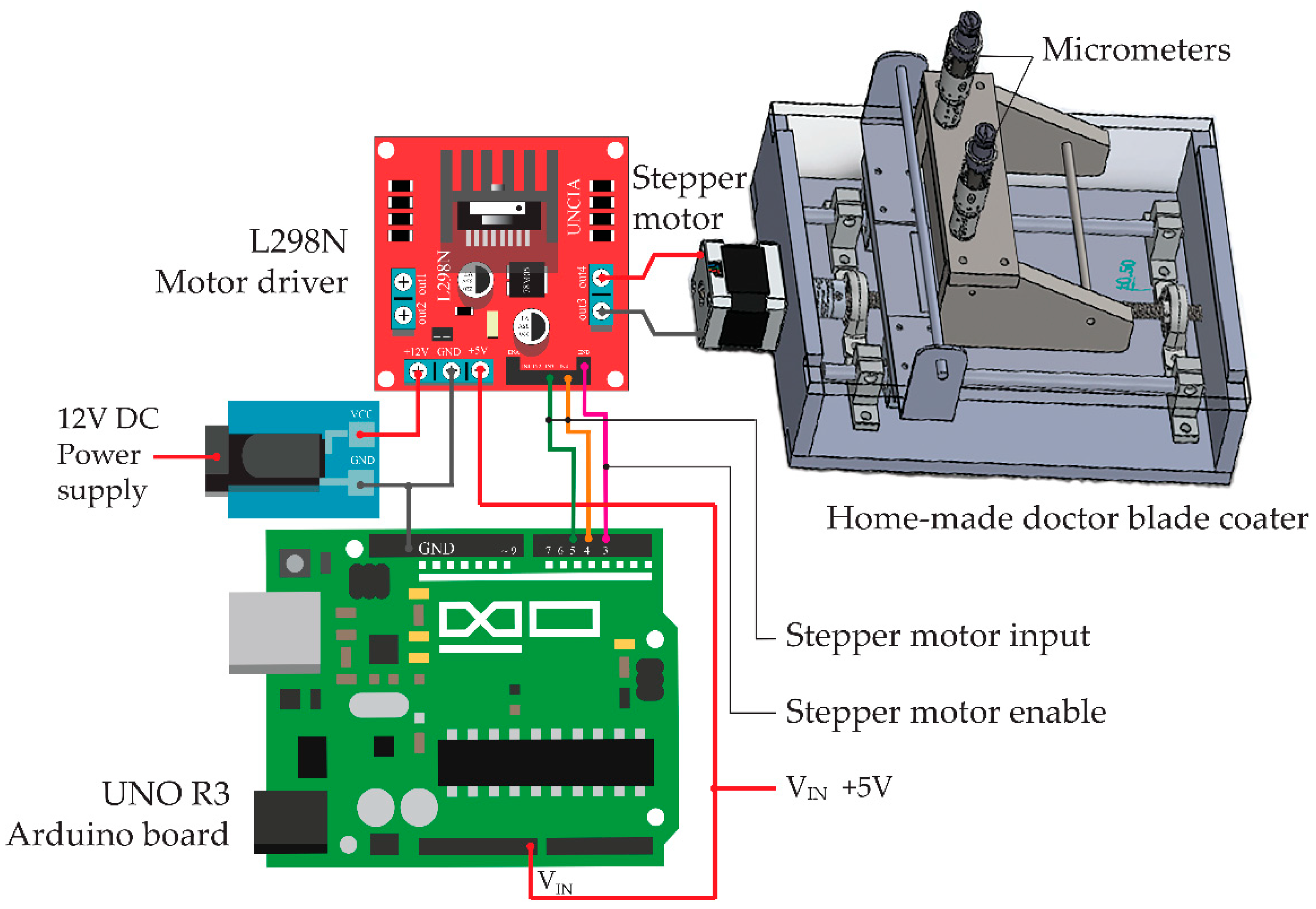
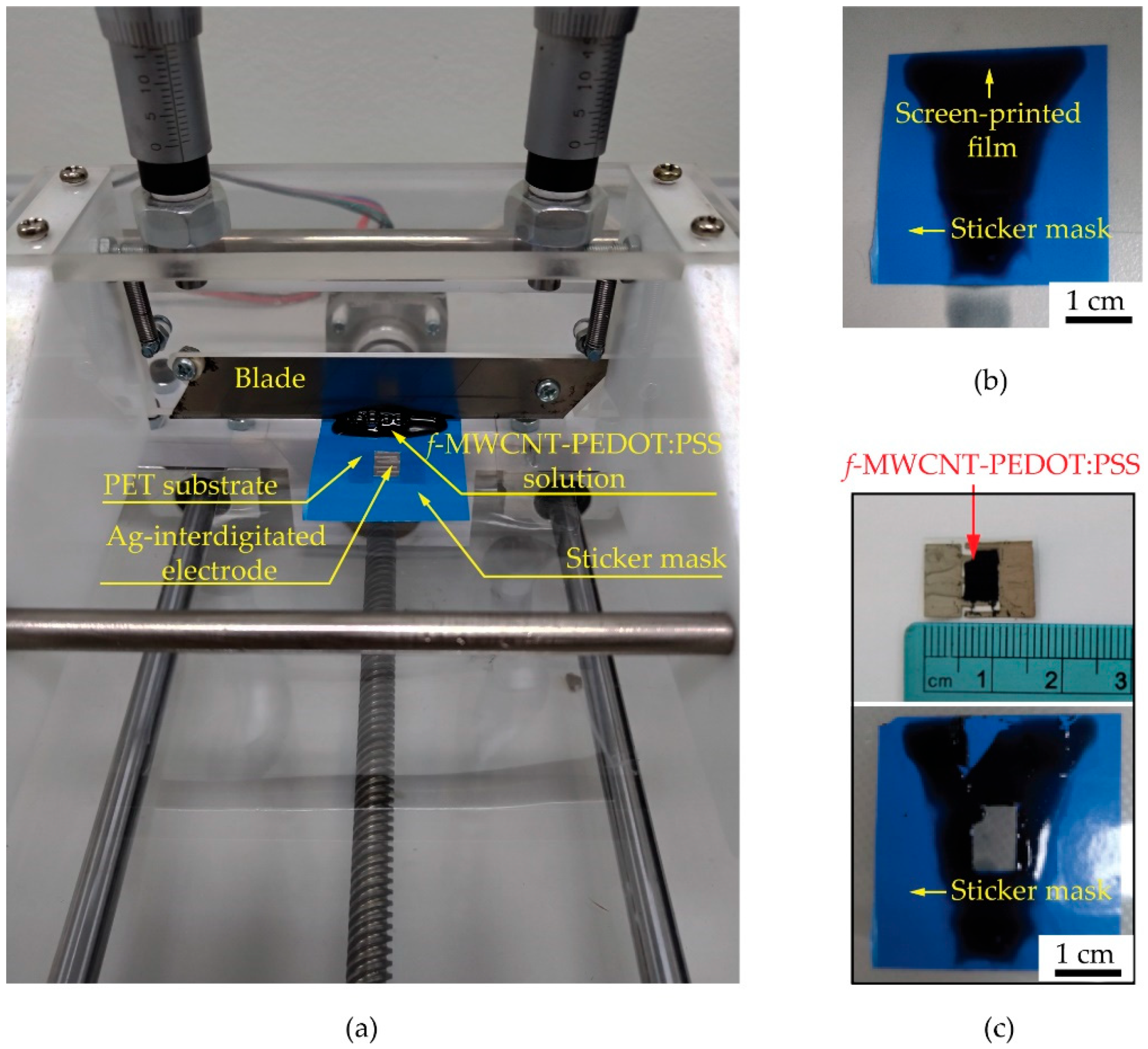
f-MWCNTs embedded in PEDOT:PSS, DMSO, EG and Triton X-100 in each condition were screen-printed on polyethylene terephthalate (PET) substrates by using a homemade-doctor blade coater controlled with a UNO R3 Arduino board and an L298N motor driver as shown in
Figure 1. A stepper motor in a doctor-blade coater was supplied by a 12 V DC power supply in order to rotate the motor to drive the blade movement along the screen-printing path with a speed of 0.5 cm/s. During the screen printing, a 0.3 N perpendicular force was applied on the substrate modulated by a blade and two micrometers. A UNO R3 Arduino board supplied by a 5 V DC power supply was conducted to compile and control all functions in the system through the input and to enable the channels. To prepare the S0, S1, S2, S3 and S4 gas sensors, the S0, S1, S2, S3 and S4 samples were screen-printed onto PET substrates with fabricated 1.0 × 1.6 cm
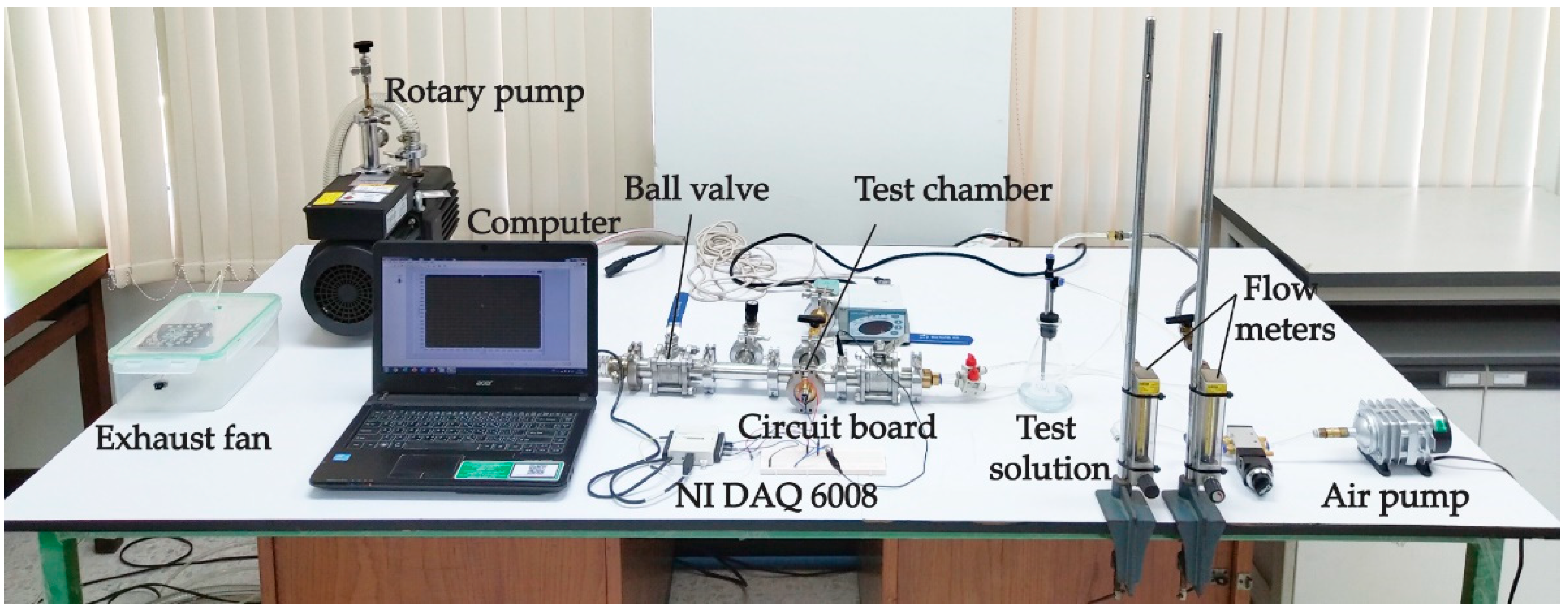
2 silver interdigitated electrodes. The sensors were evaluated on the basis of their sensing performances under gas ambient using a flow-through system as shown in
Figure 2. The composition of the system consists of an air pump, an exhaust fan and a rotary pump, two flow meters, a circuit board and two ball valves. The sensor was placed into a four-way cross fitting as a test chamber while a voltage divider circuit was also connected to the test chamber. A rotary pump was used to evacuate and remove the remaining gas out of the chamber before supplying the air and test gas into the chamber for the gas-sensing measurement. A laptop operated with LabVIEW software and an NI USB DAQ 6008 device was used to monitor the gas-sensing signals by measuring the resistance of a gas sensor every second. After the gas-sensing measurement, an exhaust fan was used to drain all gases to the outdoors.
3. Results and Discussion
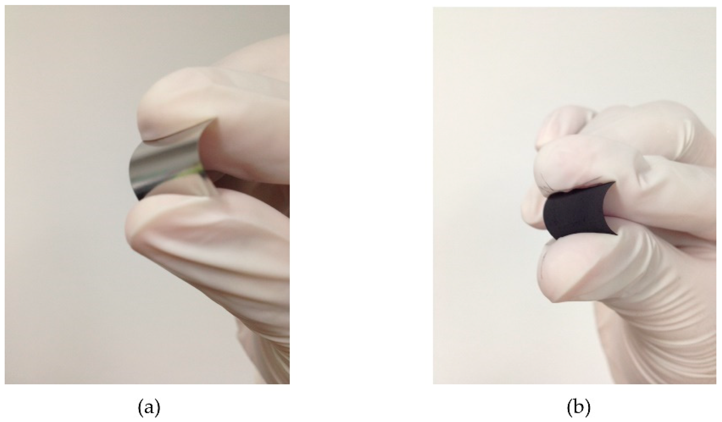
After the CVD process, the MWCNTs were grown on a full area of 304 SS foil.
Figure 3 shows a photograph of a 1.6 × 3.0 cm
2 304 SS foil before (
Figure 3a) and after (
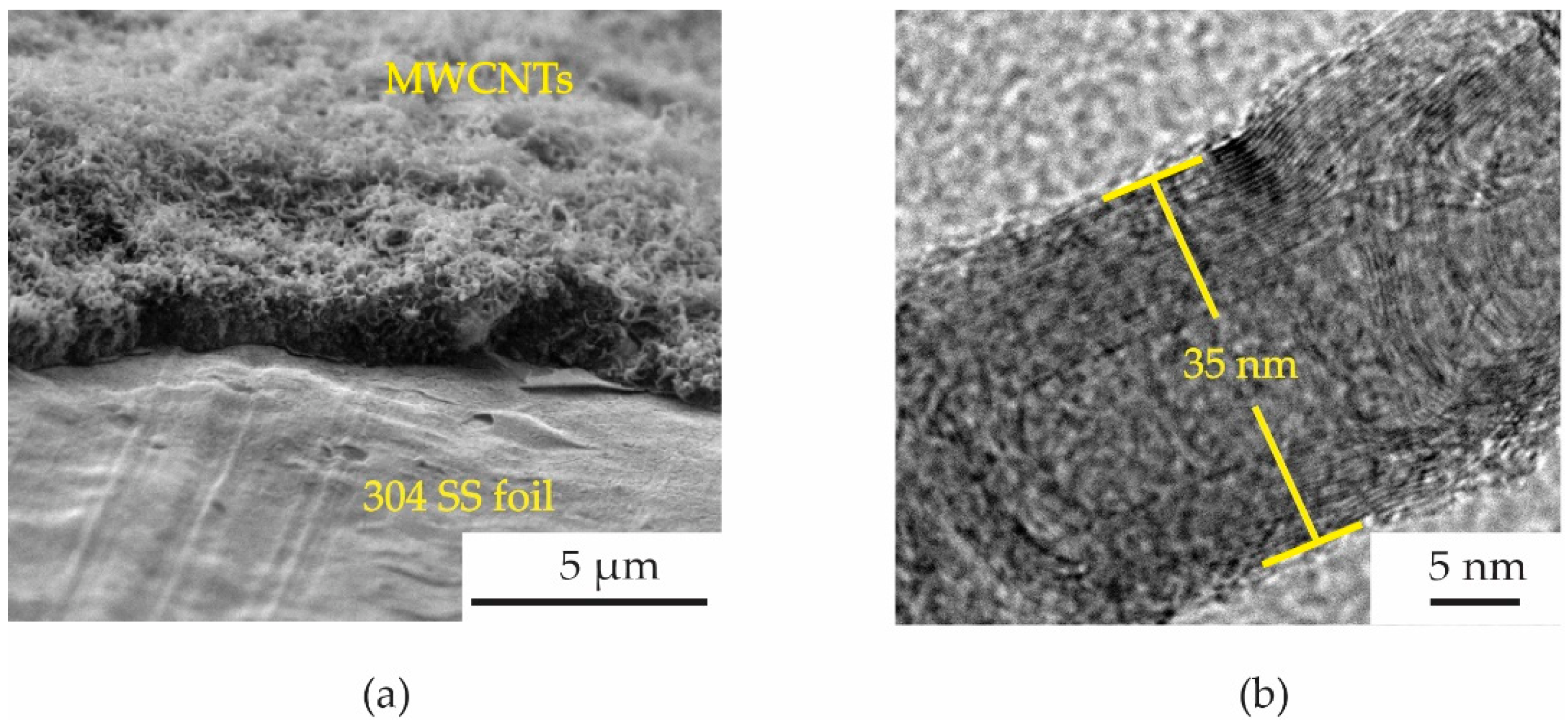
Figure 3b) CVD process. Surface morphologies of MWCNTs grown on 304 SS foil were characterized by scanning electron microscope (SEM, Quanta 450 FEI) with a working voltage and current of 30 kV and 10 μA. To observe the density of MWCNTs more easily, a Scotch
® tape was conducted to remove the MWCNTs from some area of the foil as shown in
Figure 4a. The MWCNTs on the 304 SS foils were ultrasonically sonicated in the DMSO solvent and dropped onto a copper grid. It was then inserted into a sample holder of a high-resolution transmission electron microscope (HRTEM, Hitachi HT 7700). The HRTEM was conducted using an accelerating voltage of 200 kV with a current of 60 μA to examine the size of MWCNT diameter. It can be confirmed that the samples are multiwalled carbon nanotubes with a diameter size of ~35 nm, as shown in
Figure 4b. The diameter measurements were calculated using an ImageJ software program in five different areas of the sample. It is seen that the average size of the diameter for the MWCNTs was found to be 35 ± 5 nm. The MWCNTs were functionalized with carboxylic groups (COOH) on their surfaces using oxidation and acid (3:1 H
2SO
4/HNO
3) treatments. Furthermore, 0.5 g of functionalized MWCNTs (
f-MWCNTs) was continuously sonicated in 80 mL DI water for 45 min. The
f-MWCNT solutions in each condition were then conducted to prepare the conductive solution by continuous dissolution in PEDOT:PSS, DMSO, EG and Triton X-100. The surface morphologies of
f-MWCNT-PEDOT:PSS at different sensors of S1, S2, S3 and S4 can be seen in
Figure 5. As the content of
f-MWCNTs in the solution increases, the density of PEDOT:PSS tends to decrease. The formation of functional groups on
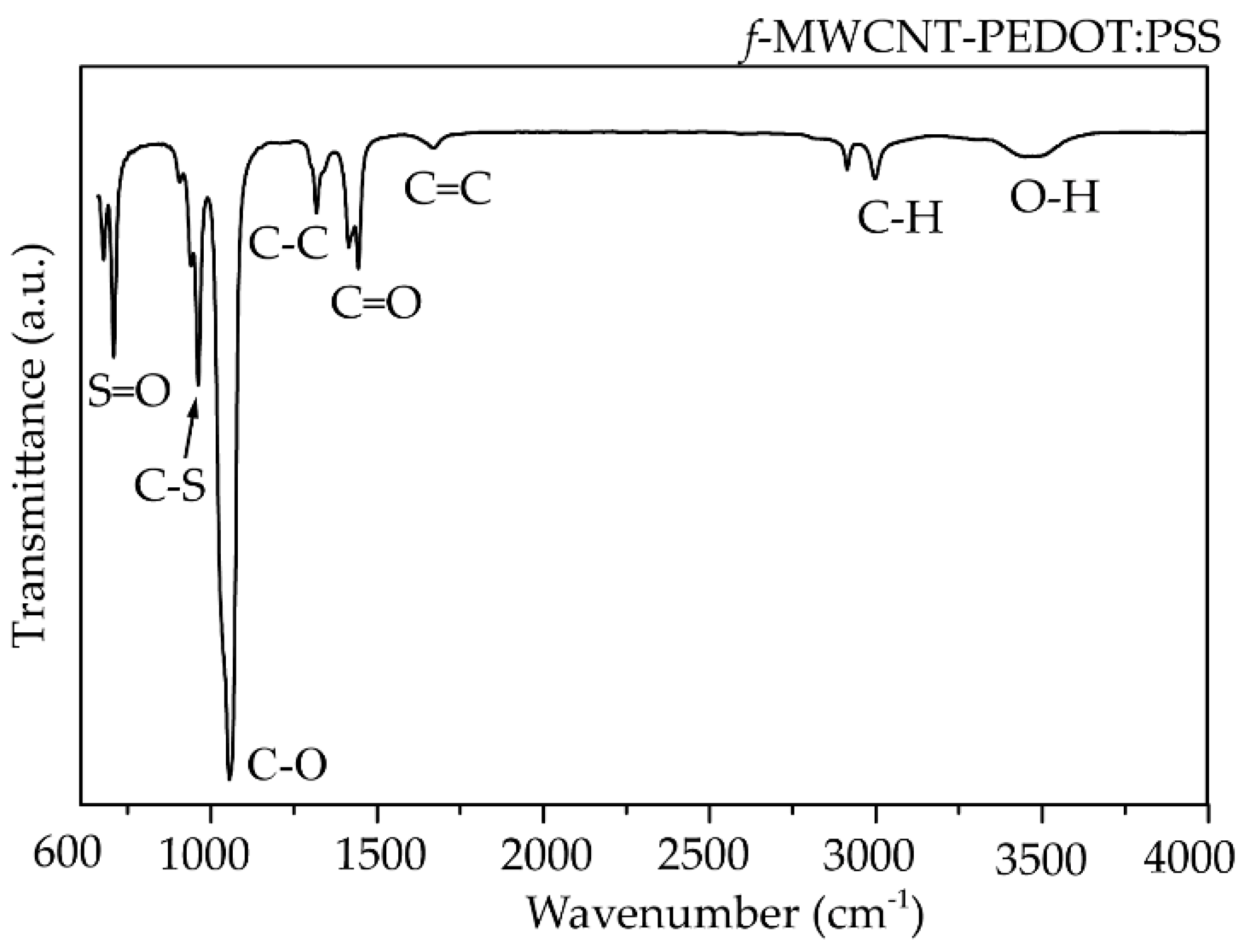
f-MWCNT-PE the DOT:PSS surfaces was characterized using a Fourier transform infrared spectrometer (FTIR, Perkin Elmer Spectrum One) as shown in
Figure 6. The weak peak at 1625 cm
−1 might be assigned to the C=C stretching mode of the graphitic layer for MWCNT. This peak is weak because of the symmetry of the dipole moment on the graphitic layer [
13,
20]. In the case of the spectrum for
f-MWCNT-PEDOT:PSS, the peaks contain C-S bond at 705, 858 and 946 cm
−1 [
20]. The peaks at 658, 1095, 1412 and 1713 cm
−1 indicate the stretching mode of S=O, C-O, C-C and C=O in carboxyl stretching modes, respectively. The dual peaks at about 2900 cm
−1 for the C-H stretching mode might represent contaminations of hydrocarbon in the spectrometer. The broad peak at around 2900 cm
−1 is responsible for the O-H groups [
21]. This indicates the presence of the formation of carboxylic (COOH) groups on the surface of
f-MWCNTs embedded in PEDOT:PSS. The
f-MWCNTPEDOT:PSS solution was deposited onto a PET substrate with a fabricated silver interdigitated electrode with a designed screen-printing system.
Figure 7a shows a photograph of a home-made doctor blade coater and its parts. The screen-printed film of
f-MWCNT-PEDOT:PSS gas sensor before and after peeling the sticker mask can be seen in
Figure 7b,c, respectively. The size of
f-MWCNT-PEDOT:PSS sensing film is 0.6 × 0.8 cm
2, as shown in
Figure 7c. After the screen-printing process, the sensor was placed into the test chamber of the gas-measurement system. The sensor was investigated for its response to NH
3 and other target gases at room-temperature.
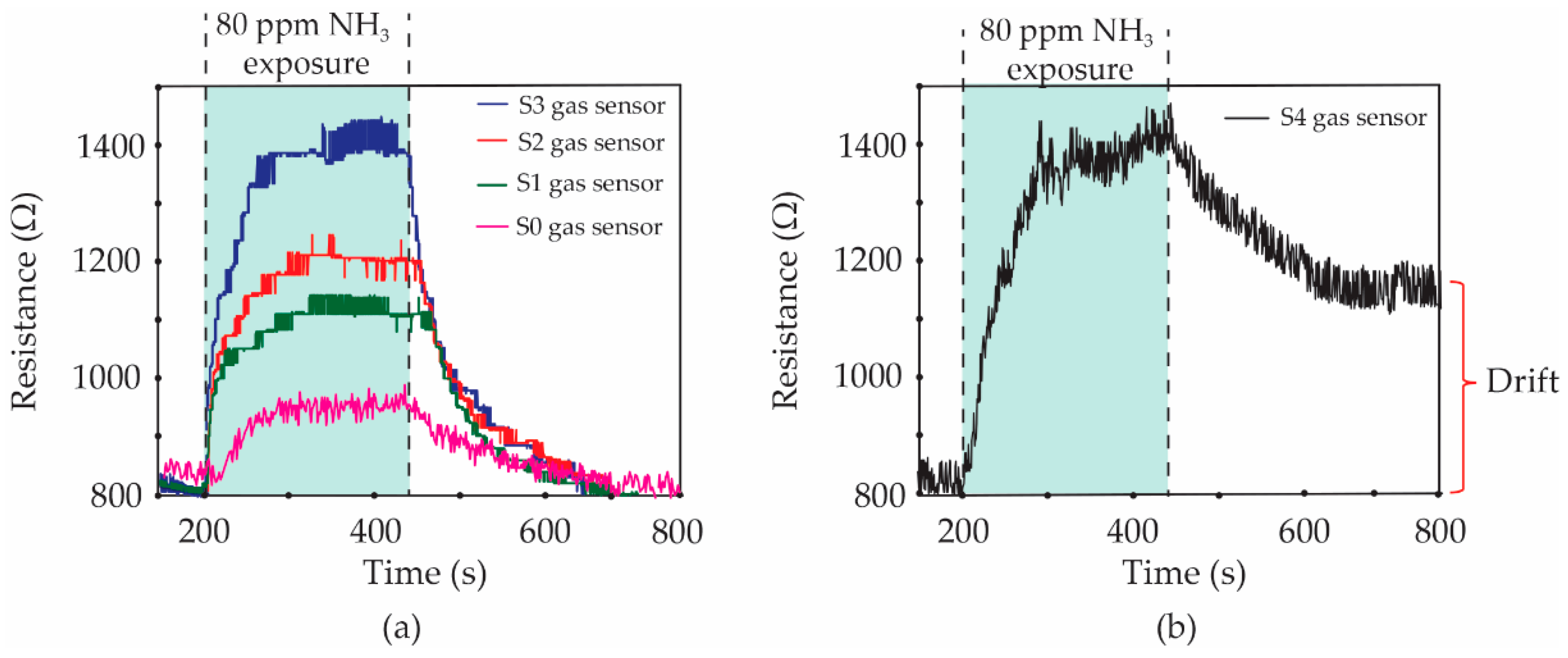
Figure 8 shows the resistance changes of S1, S2, S3 and S4 gas sensors under 80 ppm NH
3 exposure.
More specifically, the gas sensor without
f-MWCNT content (S0 gas sensor) was further characterized as a comparison. It is seen that the baseline resistances of all fabricated gas sensors are found to be ~830 Ω. Then, all of the dynamic resistances of sensors increase when the sensors are exposed to 80 ppm NH
3 vapors. However, the resistances of S0, S1, S2 and S3 sensors recover completely to their baseline after the valve of NH
3 vapors is closed, as can be seen in
Figure 8a. For the high
f-MWCNT content of the S4 gas sensor, it was interestingly observed in
Figure 8b that the resistance cannot return to its baseline line, although the NH
3 flow stopped. The gas sensors were evaluated in terms of their performances using gas response, selectivity, response time, recovery time and drift value. The gas response was defined by Equation (1).
where R
gas and R
air are the gas-sensor resistances in test-gas and dry-air flows, respectively.
The calculated values of gas response for the S0, S1, S2, S3 and S4 sensors under 80 ppm NH3 exposure were 14.5, 32.5, 44.6, 66.3 and 67.5%, respectively. It was found that the gas response of all sensors increased with an increasing f-MWCNT contents. However, the gas sensor with a high content of f-MWCNTs (S4 sample) demonstrated no noticeable return to the baseline resistance. The drift value of resistance for the S4 sensor was ~350 Ω. It is known that this value is not impressive for sensor preparation. Therefore, the optimum f-MWCNT content for the fabrication of an effective f-MWCNT-PEDOT:PSS gas sensor exposed to 80 ppm NH3 is 3% v/v of f-MWCNT solution (S3 sample). The time of the change for the sensor resistance after a gas-sensing cycle is defined as the response time. For all of the sensors, the response time was found to be of a similar value, at ~3.8 min.
The recovery time of the sensor has been further defined by the time of resistance change and recovery to its baseline. It is seen in
Figure 8a that the recovery time of S0, S1, S2 and S3 sensors was a duplicate value of ~4.5 min. For the S4 sample, it cannot be indicated in the recovery time due to the fact that the resistance of the S4 sensor does not perfectly return to its baseline. Normally in physisorption, the gas molecules accumulate on the sensing surface due to weak force, known as Van der Waals forces. The chemisorption involves the strong chemical bonding of the adsorbate with the surface of the adsorbent. Therefore, the chemical adsorption requires activation energy for reversibility in nature. For the gas-sensing layer with a low
f-MWCNT content (3.0%
v/
v solution), the physisorption is stronger than the chemisorption processes in case of NH
3 sensing by
f-MWCNT-PEDOT:PSS, while the high
f-MWCNT content (≥5.0%
v/
v solution) of the sensing layer presents very strong chemisorption. Therefore, the content of
f-MWCNTs embedded in PEDOT:PSS has an important effect on the adsorption of NH
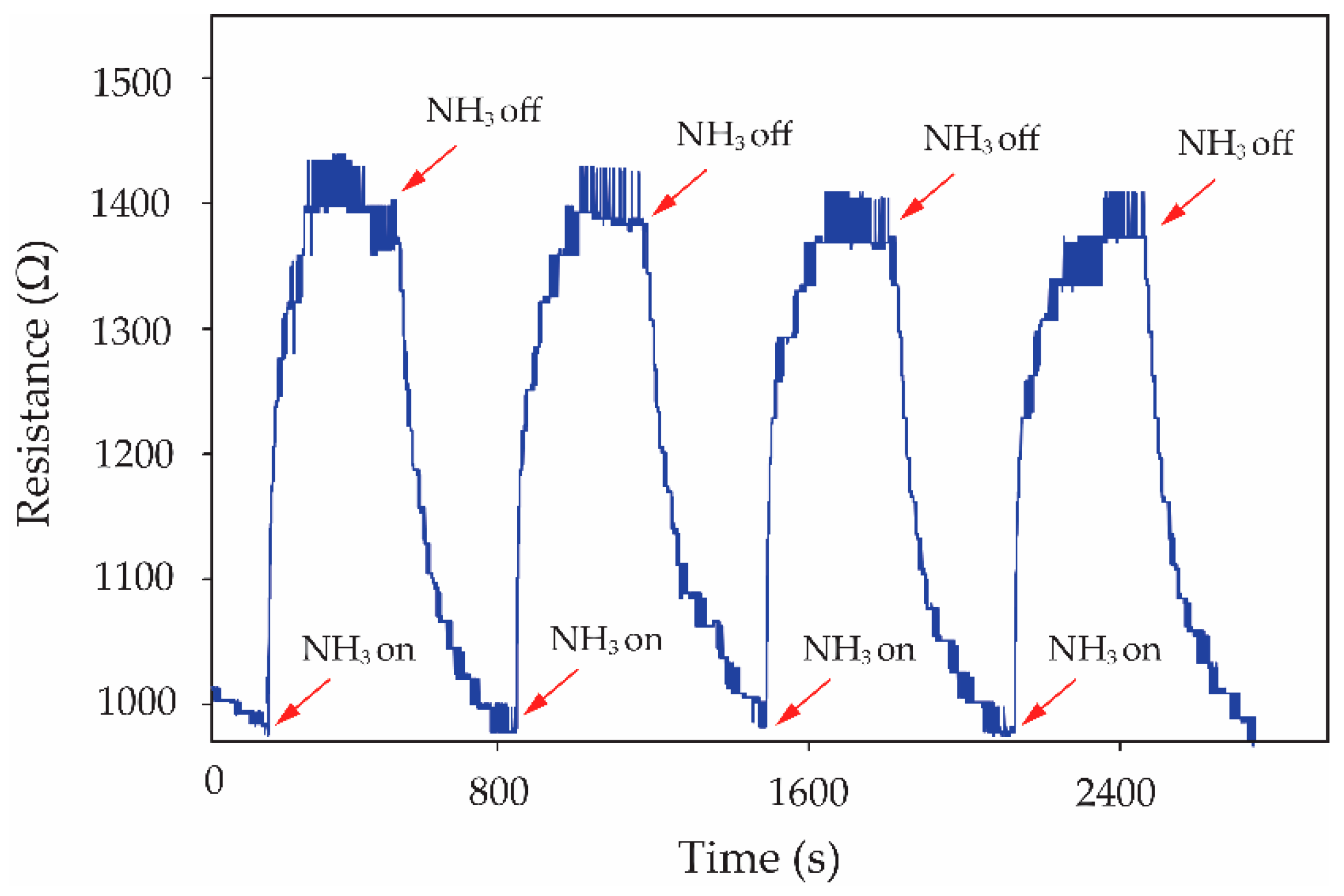
3 molecules. The effectiveness of the S3 gas sensor in handling repeated inlets of NH
3 gas is shown in
Figure 9. It can be seen that the S3 gas sensor presents a good reproducibility of the sensor for 80 ppm NH
3 exposure with excellent recovery over four cycles. The earlier publication involving the gas sensor has been focused on the reduction in the recovery time and enhancement of the recovery process. The reduction in the recovery time from 48 h to 20 min has been reported by using the combination of heat and a DC electric field to serve the desorption of NH
3 molecules from MWCNT surfaces [
22]. In this work, the
f-MWCNT-PEDOT:PSS gas-sensor with the optimum condition (S3 gas sensor) presents good performance in terms of the recovery property in dry-air flows without external excitation. The recovery time of the S3 gas sensor after 80 ppm NH
3 exposure is less than the time reported for the above work.
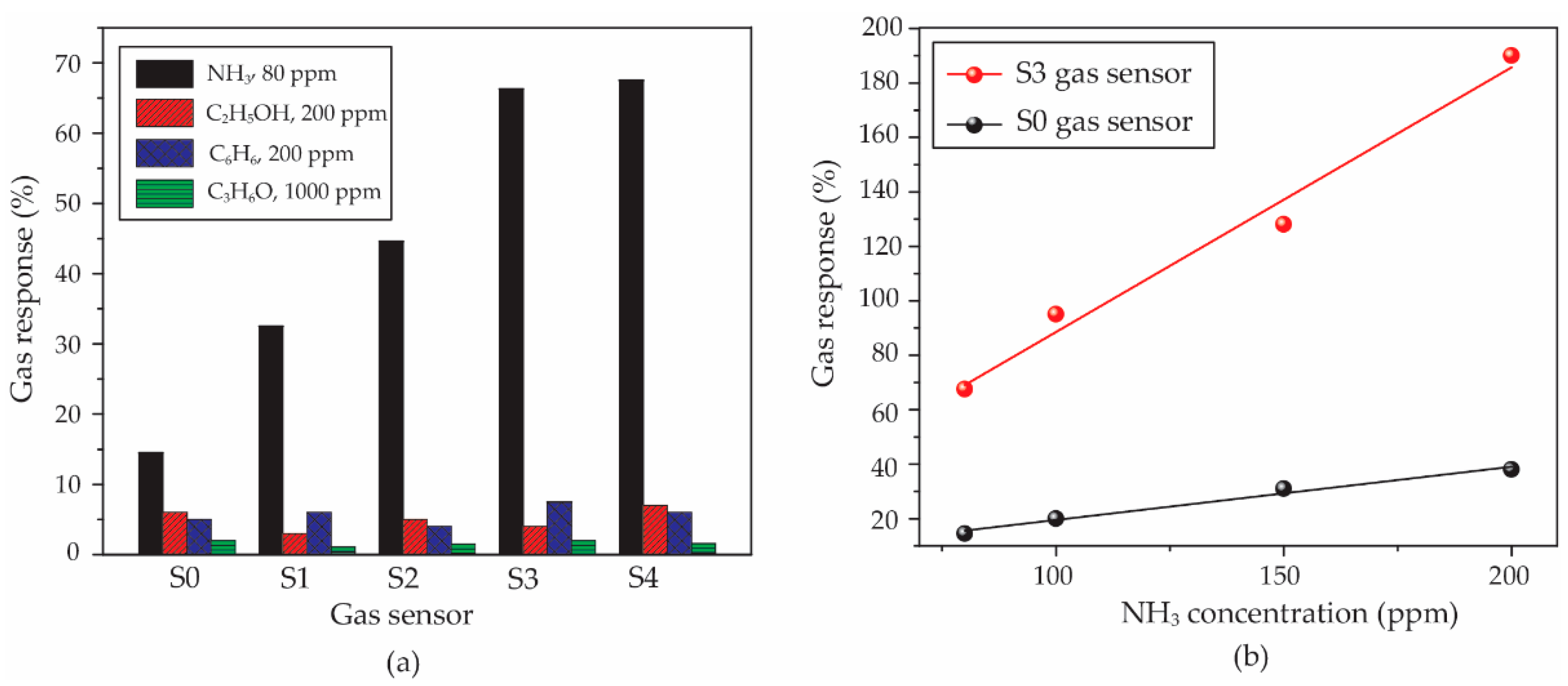
For the selectivity property, all of the sensors were compared in gas response under 80 ppm NH
3, 200 ppm C
2H
5OH, 200 ppm C
6H
6 and 1000 ppm C
3H
6O. It can be observed in
Figure 10a that the sensors show the highest response to 80 ppm NH
3, while the gas responses of all sensors exposed to other gases are lower than 10%. Therefore, the PEDOT:PSS and
f-MWCNT-PEDOT:PSS gas sensors have a good performance in selectivity to NH
3. The S3 gas sensor, as the best sample, was warranted a more thorough investigation in relation to its sensitivity property. This property has been evaluated by a slope value of a linear relation between gas concentration and the gas response of sensors under target gas. The calculated values of slopes for S0 and S3 sensors were compared. It is seen in
Figure 10b that the sensitivity values of the S0 and S3 sensors are 0.20 and 0.97 ppm
−1, respectively. Therefore, it can be indicated that the
f-MWCNT contents embedded in PEDOT:PSS leads to a better sensitivity of the gas sensor.
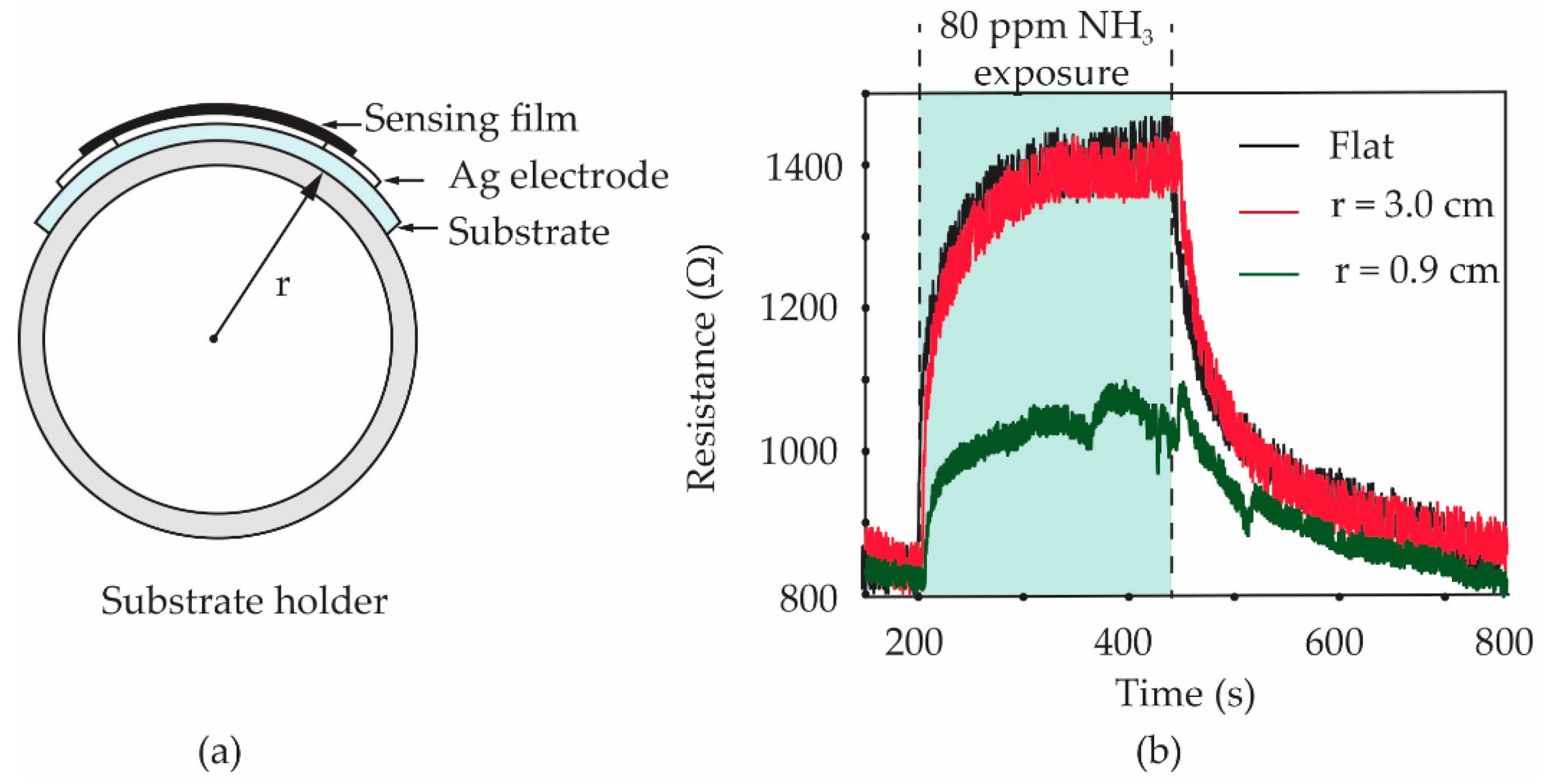
To study the effect of the bending state on the gas response of sensors, the S3 gas sensor was bent to a curvature radius of 3.0 and 0.9 cm, respectively. Furthermore, the sensor with a flat state was also tested as a comparison. Polylactic acid (PLA) filaments were printed in the cylindrical shape with an outer radius of 3.0 and 0.9 cm by a 3-dimensional (3D) printer. As shown in the diagram in
Figure 11a, a PLA cylindrical shape was used as a holder for laying a fabricated sensor on its side surface. The sensor was carefully attached to a PLA holder using a Scotch
® tape before it was inserted into a test chamber of the gas-sensing measurement system. It should be noted that only one sensor can be tested at a time. After testing the bending sensors, as shown in
Figure 11b, the gas responses of the S3 sensor under flat and 3.0 cm bending-radius states did not present an obvious difference. The calculated values of the gas response for two of the sensors are found to be 67.5 and 65.0%, respectively. For the 0.9 cm bending-radius state of the sensor, it was observed that the calculated value of gas response significantly reduced to 29.5%. The reduction in the NH
3 response for the sensor under heavy substrate-bending is further discussed based on a tensile strain effect.
To understand the tensile strain effects on the gas response of the
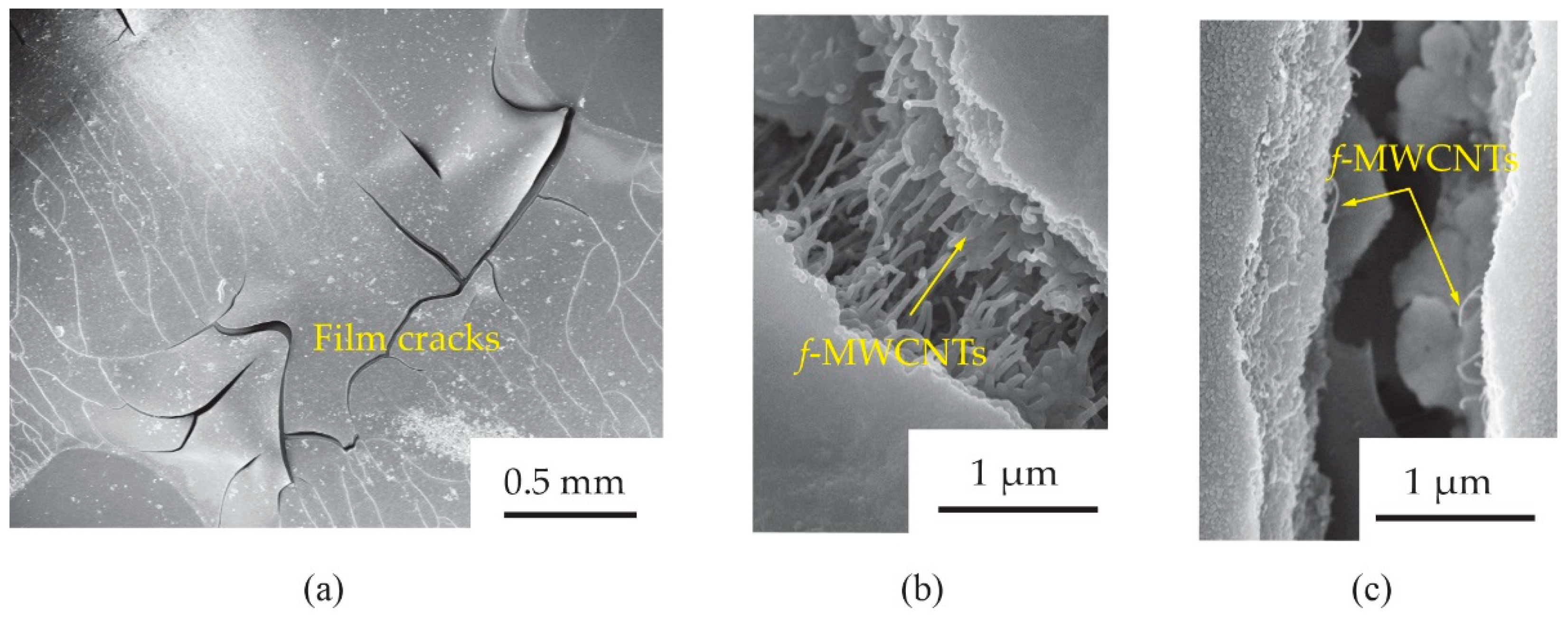
f-MWCNT-PEDOT:PSS gas sensor, the surface morphology of the S3 screen-printed film after already bending test was further investigated.
Figure 12 shows the SEM images of
f-MWCNTs embedded in PEDOT:PSS sensing films (S3 sample) after bending tests with 3.0 cm and 0.9 cm radii. It was observed in
Figure 12a that there were some cracks in the bending-film surface. The sizes of the crack gaps for the films after 3.0 and 0.9 cm bending-radius tests were found to be ~1.1 and ~1.5 μm, respectively. After a test of 3.0 cm bending-radius (
Figure 12b), there were
f-MWCNT alignments in the film, which acted as conductive pathways between the gap. For the much larger crack gap of a 0.9 cm bending-radius film (
Figure 12c), a lack of
f-MWCNT pathways was observed. Delamination, channeling and cracking have been reported as important causes for the failure of breakable films on flexible substrates [
23,
24,
25]. When decreasing the stress on the film surface, the tensile strain increased. Therefore, the crack paths on the film surface were generated. This is the most common observation for the polymer film during the bending process.
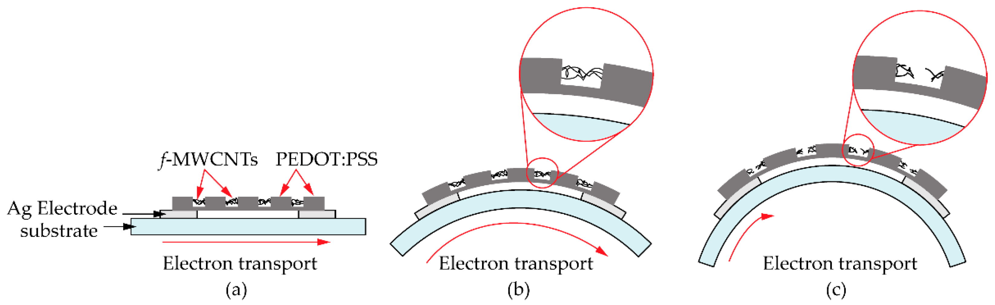
Figure 13 shows the schematic diagram of pathways in electron transports for a
f-MWCNT-PEDOT:PSS gas sensor under a flat state (
Figure 13a), 3.0 cm (
Figure 13b) and 0.9 cm (
Figure 13c) bending-radius states. The reduction in the NH
3 response for the sensor under heavy bending has been also discussed, in that the cracks generate permanent changes in the electrical resistance of PEDOT:PSS sensing films. However, the
f-MWCNTs embedded in the PEDOT:PSS act as additional pathways in electron transport. Therefore, the changes in electrical resistance of the
f-MWCNT-PEDOT:PSS sensing film with weak bending have little impact on the electrical property and gas-sensing performance. This may provide a reason as to why the gas response of the
f-MWCNT-PEDOT:PSS gas sensor under flat and 3.0 cm curvature-radius states did not lead to an obvious difference. However, due to the large crack gap in the heavy bending substrate, the sensor under 0.9 cm bending radius presents a low response to 80 ppm NH
3. This is due to the lack of
f-MWCNT connectors between the gap. This results in the creation of low conductive pathways in electron transports. Therefore, low signals of gas response for the
f-MWCNT-PEDOT:PSS gas sensor to NH
3 under heavy substrate-bending are represented.
The gas-sensing mechanism of the screen-printed f-MWCNT-PEDOT:PSS gas sensor has been proposed based on a classification of two possible mechanisms. The f-MWCNT-PEDOT:PSS gas sensor with a high f-MWCNT content has been proposed as a first possible mechanism based on a reducing reaction between chemisorbed oxygen groups on the f-MWCNT-PEDOT:PSS surfaces and gas molecules. The oxygen groups can be trapped on the surface of active materials in dry air at room temperature. In addition, the oxygen groups also tend to increase after functionalization with 3:1 H2SO4/HNO3 treatment. After the exposure of the gas-sensing film to NH3 vapor, the NH3 molecules can be adsorbed on the f-MWCNT-PEDOT:PSS surfaces. The reducing reaction between NH3 molecules and oxygen groups returns electrons to the f-MWCNT-PEDOT:PSS surfaces as a p-type semiconductor material. When the p-type semiconducting f-MWCNT-PEDOT:PSS gas sensor received electrons from NH3 molecules, the concentration of the hole in p-type semiconducting f-MWCNT-PEDOT:PSS gas sensor decreased. This leads to an increment in the electrical resistance of the f-MWCNT-PEDOT:PSS gas sensor after exposure to NH3 gas. Because of the strong bonding between the NH3 molecules and oxygen-containing groups, the NH3 chemisorbed molecules cannot be removed completely from the surface of f-MWCNT-PEDOT:PSS at room temperature, although the NH3 gas sensor is purged by the dry-air. This may lead to a creation of drift at a baseline of resistance for the f-MWCNT-PEDOT:PSS gas sensor with a high f-MWCNT content (S4 gas sensor).
With regard to the second possible mechanism, the f-MWCNT-PEDOT:PSS gas sensor with a low f-MWCNT content has been also discussed based on a direct charge-transfer process between NH3 molecules and f-MWCNT-PEDOT:PSS surfaces. Physisorption has been considered as a dominant process in the explanation of this possible mechanism. The increments in the specific adsorption area and π-π interactions can be improved by the addition of f-MWCNTs to PEDOT:PSS. The holes of f-MWCNT-PEDOT:PSS respond to donating electrons from NH3 molecules when they are adsorbed onto f-MWCNT-PEDOT:PSS surfaces. When decreasing the hole concentration, the resistance of the p-type semiconducting f-MWCNT-PEDOT:PSS gas sensor increases. Because physisorption is a weak π-π interaction, the gas molecules can be easily purged under dry air at room temperature. This may lead to the complete recovery of the baseline for the S0, S1, S2 and S3 gas sensors under the purging of dry-air at room temperature.


