1. Introduction
The triboelectric nanogenerator (TENG) uses triboelectrification and electrostatic induction mechanisms that convert several environmental energies into electricity, such as vibration, fluid, kinetic and acoustic [
1,
2,
3,
4,
5]. TENGs can scavenge with high entropy energy and provide electrical power to several low-power consumption electronic devices with proper design. These devices’ numbers can reach billions in the Internet of Things (IoT) era [
6]. In addition to energy harvesting functionality, the TENG can also be used as a self-powered sensor, which can be used for sport [
7], pulmonary [
8], configurational [
7], wind [
9], and motion [
10] sensing applications.
The TENG has high voltage, low current, and high internal impedance properties. These attributes make the corresponding measurement and instrumentation development essential in the research and development period.
The low current value can be measured using a feedback or shunt ammeter. In general, the feedback ammeter has a better resolution and less burden voltage than the shunt ammeter. For instance, the low-noise current amplifier SR570 is widely used in the TENG’s short circuit measurement [
11,
12,
13]. A low-cost current preamplifier is developed in [
10]. It shows identical current waveforms compared with the SR570 approach [
14]. The TENG’s open-circuit voltage can be measured using an electrometer, owing to its input resistance reaching up to T-Ohm level [
15,
16,
17,
18]. Another voltage measurement approach uses the oscilloscope/digital multimeter and high voltage probe, which allows a high-speed and large-amplitude voltage measurement [
19,
20,
21,
22]. Hong et al. [
23] propose a testbed for the contact-separation-type TENG to precisely and quantitatively benchmark the TENG’s performance. They then develop another testbed suitable for the rotational TENG’s performance evaluation [
24]. Sharma et al. [
25] propose a comprehensive test workbench, which allows the discovery of TENG’s performance in an affordable approach.
In addition, it is always essential to find the TENG’s output power curve versus different load resistance values, which helps us to evaluate the TENG’s performance intuitively. The resistance tuning and power tracking processes are tedious. However, they are highly repeatable. Therefore, this task can be automatically fulfilled, which has not been reported yet.
In this paper, a computer-controlled Automated Power Evaluation Workbench (APEW) is designed and developed to obtain the TENG’s power curve automatically. A resistance schedule algorithm is also proposed, making the synthesized resistance value with the minimum change step of 1 Ohm. Physically, the resistance value is scheduled and controlled by relays. The synthesized resistance value is formed with proper tuning of the relays’ ON/OFF status, which is governed by the resistance schedule algorithm.
2. Resistance Synthesis Principle and Development
2.1. Resistance Decomposing and Synthesis
The TENG’s principle consists of coupling contact electrification and electrostatic induction, with inherent capacitance properties. The total voltage difference between the two electrodes can be expressed as [
26]:
where
is the distance between the two electrodes,
represents the transferred charges,
denotes the TENG’s inherent dynamic capacitance, and
is the TENG’s open-circuit voltage.
Therefore, the equivalent circuit model of TENG has a serial connection of an ideal voltage source with a variable capacitor.
The TENG’s equivalent circuit model is presented in
Figure 1. The TENG’s internal impedance is
, its external load resistance is denoted by
, and the load voltage is represented by
.
The detailed expression of
and the consumption power
can be expressed as:
Hence, the TENG’s output power is highly related to the external load resistance . In order to automatically obtain the TENG’s output power curve, several external resistance values should be synthesized in a well-organized manner. However, the number of resistors should be limited to ensure that the measurement system is physically realizable.
The synthesized resistance
(integral value) is designed using the Octal decomposition principle. The target resistance value is the resistor (
) summation from N different columns, where each column comprises eight rows. Each column only allows one element to feed through the circuit at one time. The
value is given by:
where
represents the row number,
denotes the column number, and
is the corresponding resistance value which follows the Octal decomposition principle.
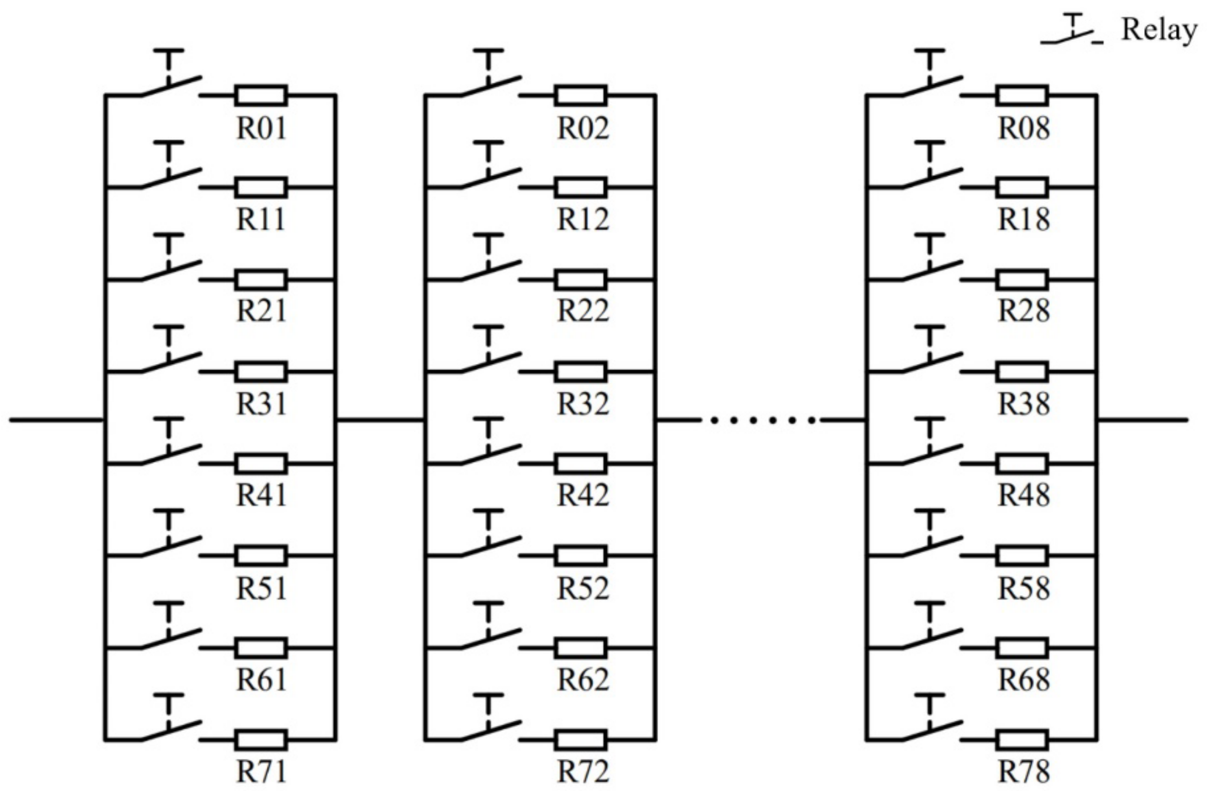
For instance, considering that the resistors are divided into eight columns, each column comprises eight parallel resistors, and a relay accompanies each resistor, the schematic diagram of the resistance synthesis is presented in
Figure 2.
Only one relay in each column is allowed to be closed at one time, and the synthesized resistance is the summation of the eight resistors from the eight corresponding columns. The resistance values in the
th column should satisfy
. The calculated resistance values are presented in
Table 1.
Considering that a large portion of the calculated theoretical resistance values is not available from commercial products, the used resistance values for system realization are presented in
Table 2. The selecting rule is that the resistance value for implementation is smaller than the theoretical value. However, it is the closest to it. In addition, the synthesized element comprises three resistors placed in series.
2.2. Resistance Schedule Algorithm
In order to evaluate the TENG’s output power, the resistance value should be changed in a programmable manner. Therefore, a scheduling algorithm able to form specific resistance values according to the Octal decomposition principle and provide switching signals to the corresponding relays is required. When switching signals are generated, specific relays are closed, which indicates that the accompanying resistor becomes one part of the synthesized resistance.
For instance, the resistance values shown in
Table 2 are used to form the desired resistance value. In the proposed schedule algorithm, Column 8 is the start searching point. Compared with the desired resistance value, the smallest and closest element is selected in this column. The selected element subtracts the desired resistance value in Column 8 and searches the smaller and closest element given in Column 7. This process continues until the resistor shown in Column 1 is determined. For instance, if the desired resistance is 240
, after this algorithm computation, the obtained composed element values are 4
for Column 1, 24
for Column 2, 320
for Column 3, 2.56
for Column 4, 8.192
for Column 5, 228.9
for Column 6, 0
for Column 7 and 0
for Column 8.
The detailed flowchart of the resistance schedule algorithm is presented in
Figure 3.
3. APEW Realization
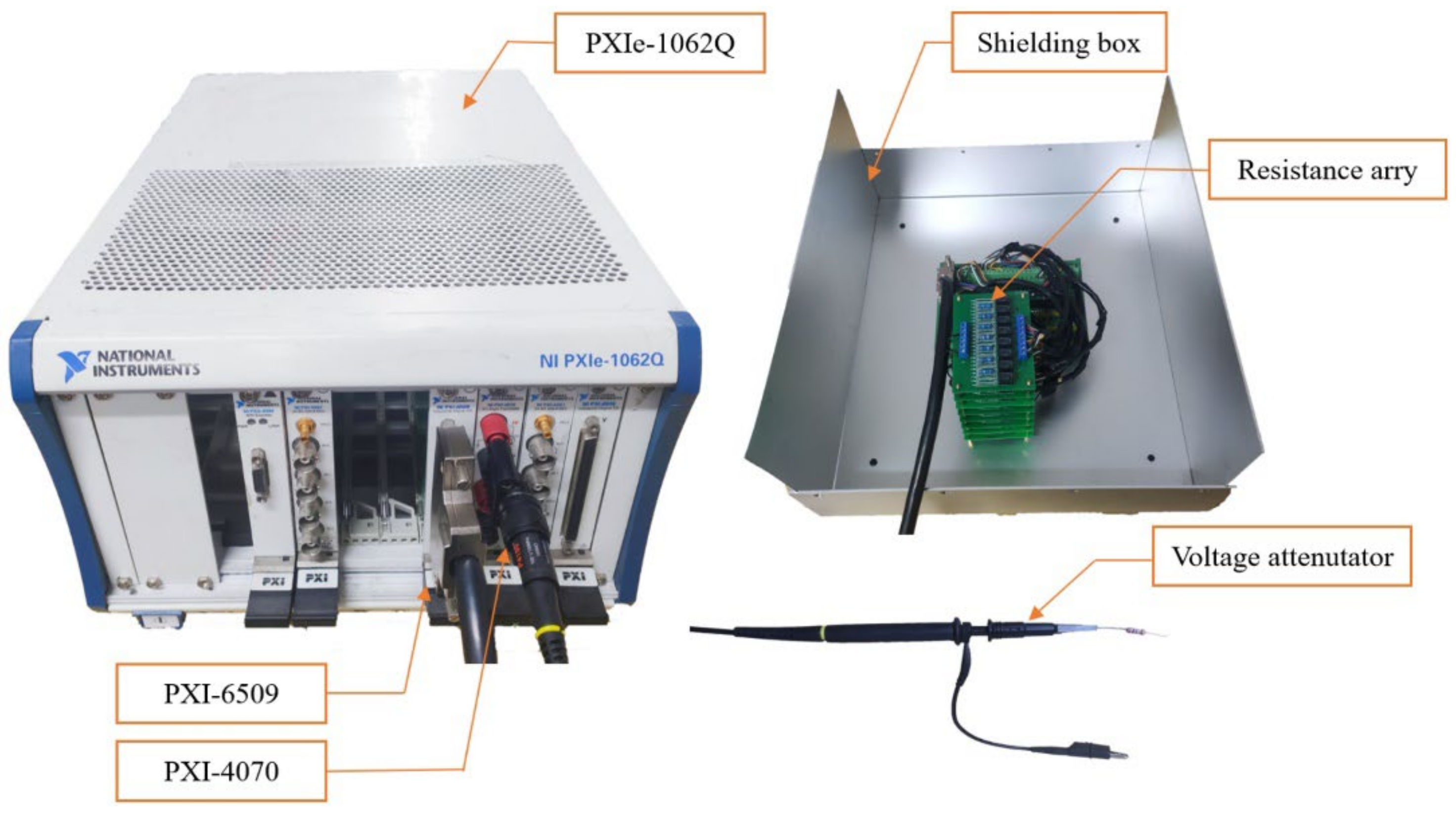
Relays (Omron G5V-1 DC5V), carbon-film resistors (1% accuracy), a PXI-6509 digital IO module [
27], and a PXI-4070 digital multimeter module [
28] are selected as the APEW components (
Figure 4).
A voltage attenuator is built up to minimize the impedance loading effect and allow high voltage measurement capacities. The attenuator’s internal resistance is 530 , which achieves 530:1 voltage attenuation when the input resistance of the PXI-4070 is set to 1 . Note that the actual voltage is re-scaled in the software.
The programable resistance array is connected to the TENG in series. It is controlled by the PXI-6509 DIO module, which is equipped with 96 DIO lines to drive the relays. When the status of the digital line is set to “ON”, a DC 5 V signal is generated at the digital output line, which brings an electromagnetic force to operate the switch. This results in linking the subsequent resistor of the relay to the measurement circuit. When the status of the digital line is set to “OFF”, a DC 0 V signal is generated at the digital output line. Consequently, the relay disconnects the resistor from the measurement circuit.
The resistors are formed by modules, which are presented in
Table 2. When the synthesized resistance is generated, its voltage will be scaled by the voltage attenuator. This voltage value is acquired by the PXI-4070 module and then processed by the LabVIEW software.
4. Experiment Verification
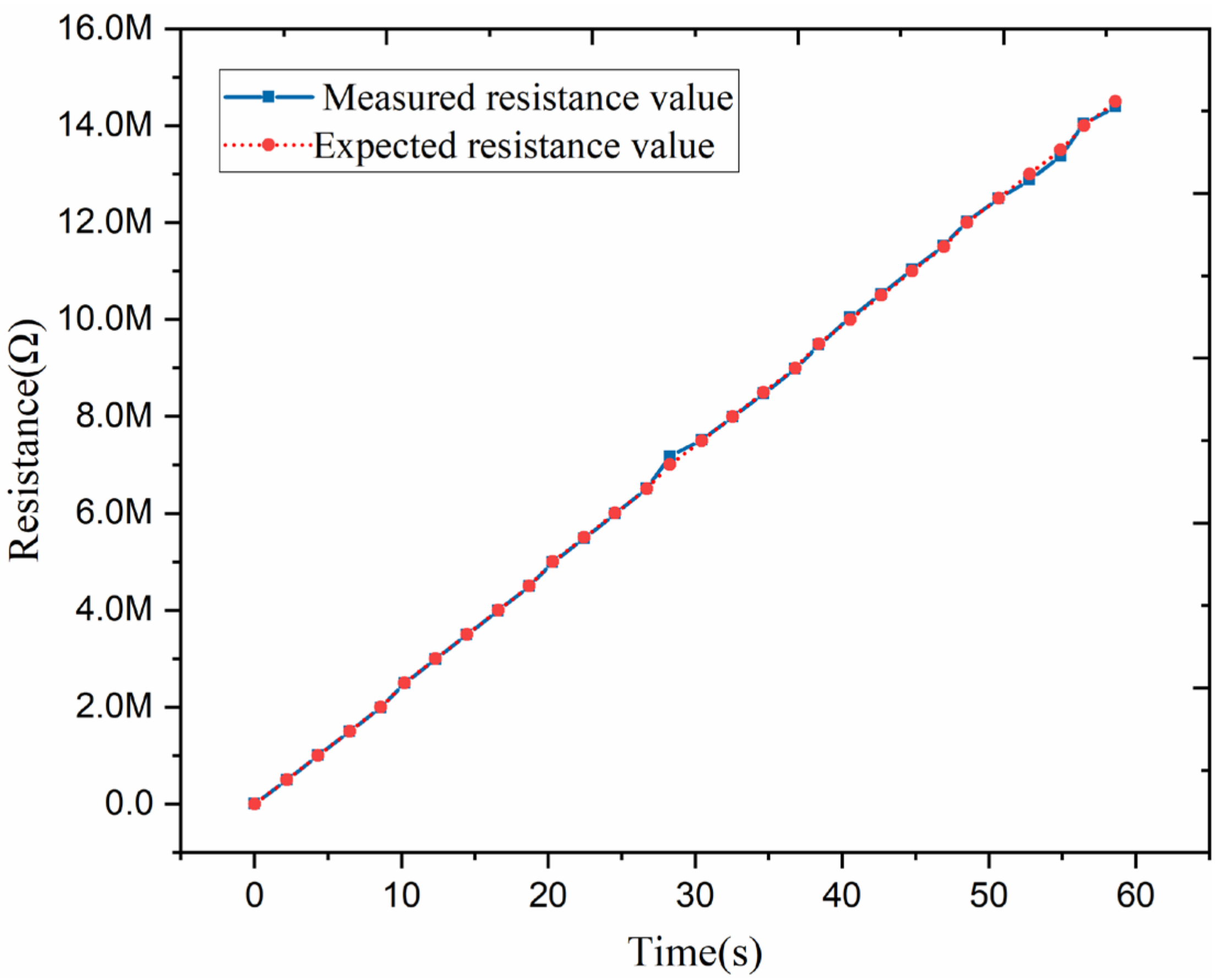
4.1. Synthesized Resistance Verification
It is essential to verify the synthesized resistance values’ correctness before performing the power evaluation step. In the test case, the initial resistance value, final resistance value, and resistance value change are set to 0
, 14
, and 0.5
per two seconds, respectively. The PXI-4070 multimeter is used to measure the synthesized resistance. The measured data are presented in
Figure 5. The test data indicate that the resistance can be programmably synthesized in the desired manner and used for TENG power evaluation.
4.2. Power Evaluation
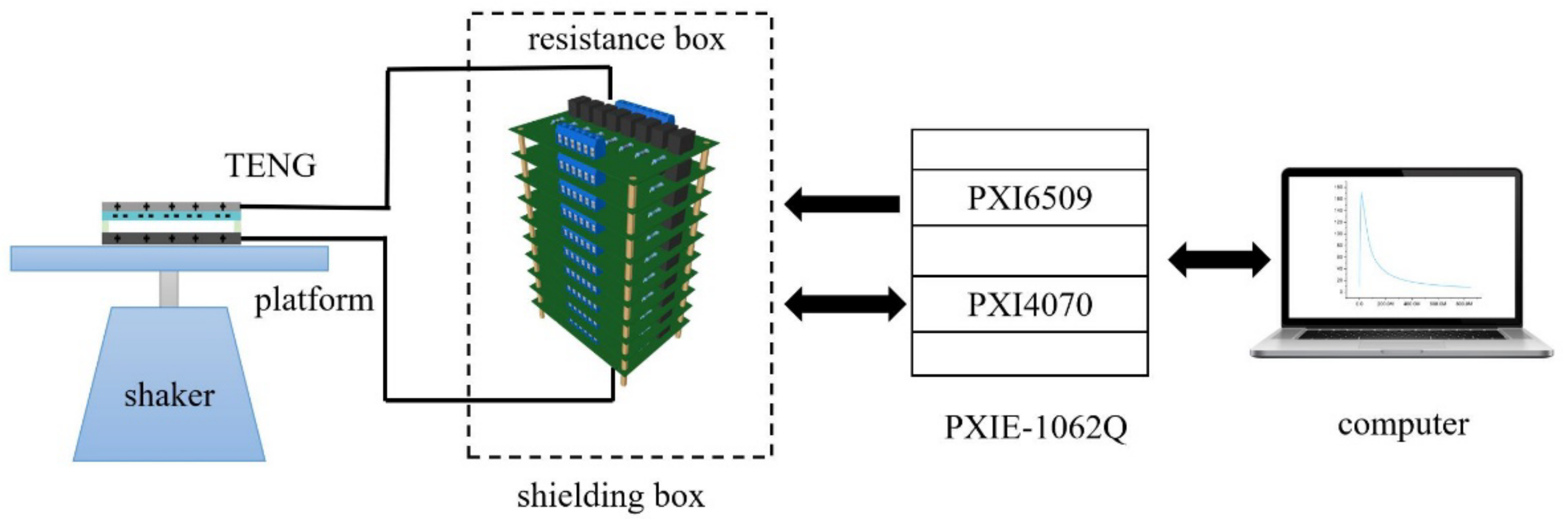
A TENG device is placed on a vibration shaker, generating a contact-separation movement under harmonic vibration excitation. The APEW is connected to the TENG in series. A metallic box shields the resistance circuit boards to prevent electromagnetic interference. The PXI-6509 module is used to control the relays according to the proposed algorithm. In addition, the PXI-4070 module is used to acquire the voltage waveform across the synthesized resistor. The schematic diagram of the experimental power evaluation system is illustrated in
Figure 6.
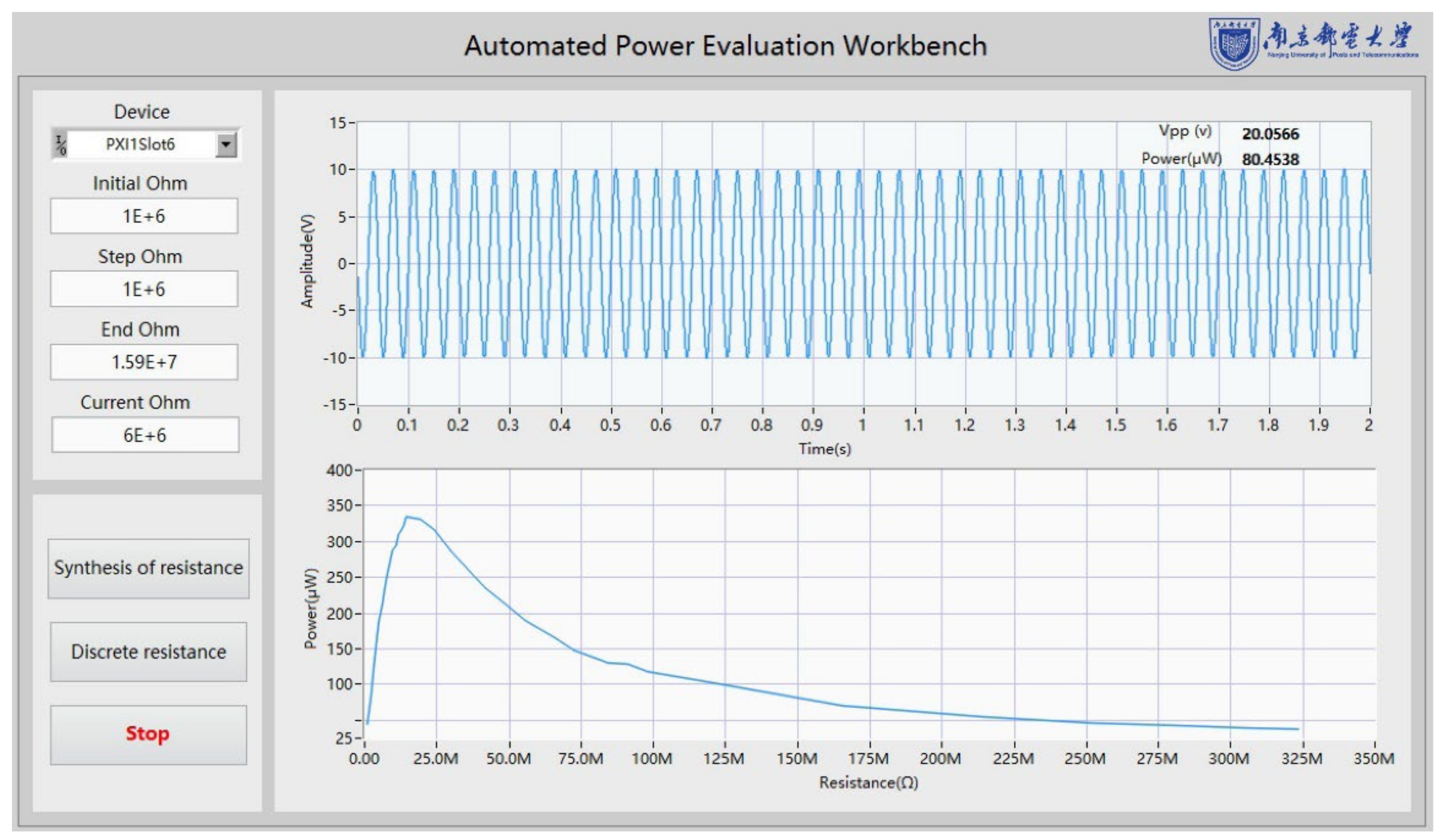
The software interface is presented in
Figure 7. After a complete round, the power curve can be automatically generated and shown in the front panel of the software.
The “Initial Ohm” sets the minimum load resistance value during the test, while the synthesized resistance increases according to the “ Step Ohm” value. When the “Synthesis of resistance” is pressed, the APEW starts to work. Considering the resistor’s accuracy and accelerating measurement speed, when the synthesized resistance value is greater than 15 , 16 fixed large-value resistors are used as external load. Consequently, a quicker test process is performed when the “Discrete resistance” button is pressed, covering the fixed large load resistance values. The collected voltage waveform is displayed in a real-time waveform diagram. When the test is completed, the output power curve of TENG is automatically generated in the waveform chart.
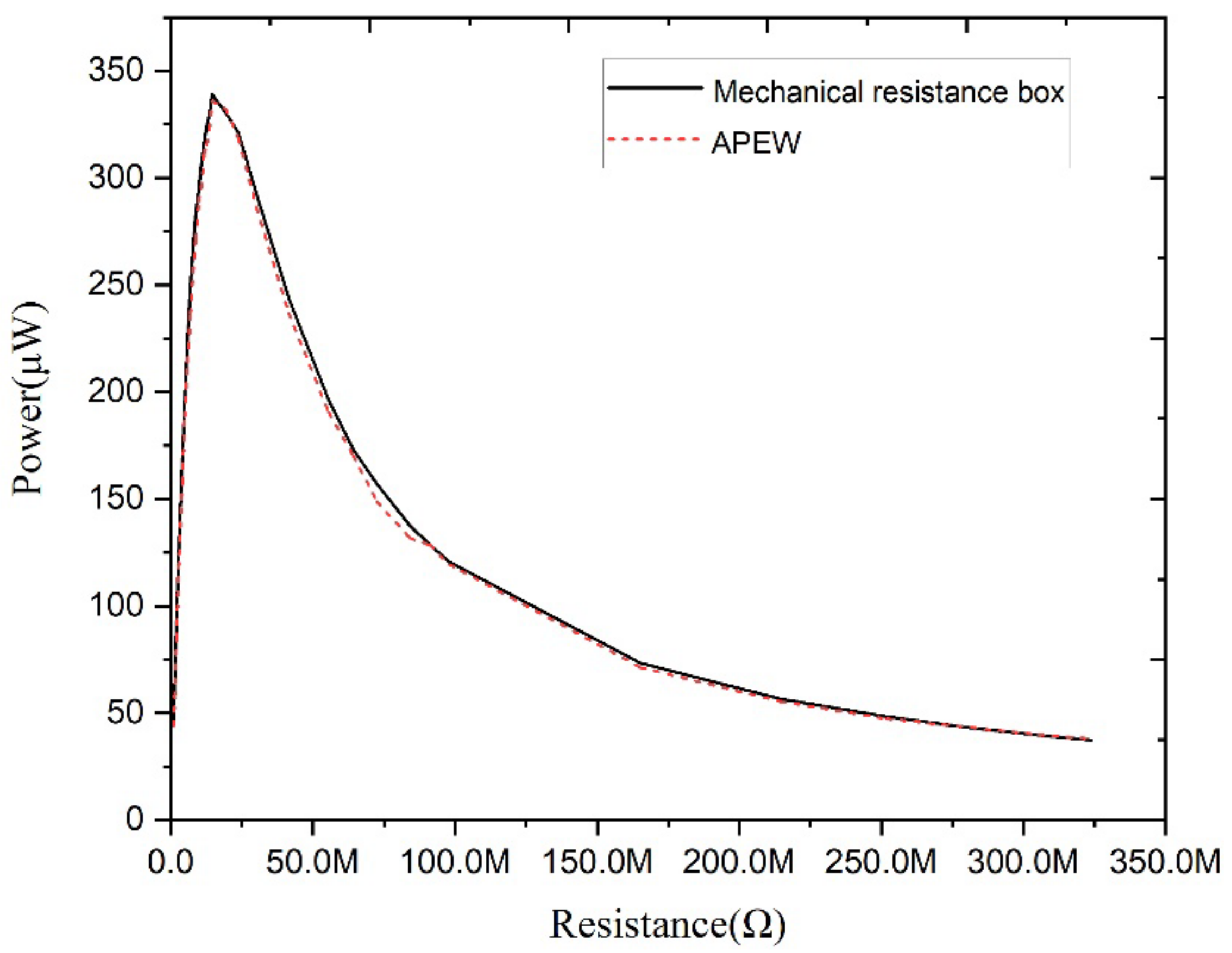
The power curve obtained by APEW is also compared with the power curve using the mechanical resistance box approach, which is a tuning process performed manually. These two curves are shown in
Figure 8.
It can be seen from the measured data of the APEW system that the TENG’s maximum output power is 335.82 and the optimal load resistance is 14.587 . On the contrary, the manual tuning’s maximum output power and optimal matching load are 338.89 and 14.587 , respectively. Therefore, the power deviation is 0.91%, which is due to the accuracy of the electronic components and variation om the parasitic parameters. Consequently, the experimental data justify the feasibility of using APEW to obtain the TENG’s output power curve.
5. Conclusions
This paper proposes a workbench to achieve automatic power evaluation for the TENG. The arbitrary integral resistance value can be synthesized using the Octal decomposition. The resistance value increases by the preset step size when the program starts. The TENG’s output power can be automatically measured for different resistance values, followed by the resistance schedule algorithm. After the test is completed, the calculated power values are saved, and the TENG’s output power curve is generated. This APEW system reduces human intervention, operators’ workload, and error probability. Finally, all the components are modularly designed, guaranteeing flexibility, expandability, and maintainability.
Author Contributions
Conceptualization, M.Y. and Y.X.; methodology, M.Y. and C.L.; investigation, C.L. and S.Z.; writing—original draft preparation, C.L. and S.Z.; writing—review and editing, M.Y. and Y.X. All authors have read and agreed to the published version of the manuscript.
Funding
The present research was supported by the National Natural Science Foundation of China (61701250, 61974071, and 61601394), the State Key Laboratory of Mechanical System and Vibration (Grant No. MSV202018), the Priority Academic Program Development of Jiangsu Higher Education Institutions (PAPD, YX030003), and the Start-Up Fund from Nanjing University of Posts and Telecommunications (No. NY218151 and NY218157).
Acknowledgments
We thank the editor for inviting us to publish this paper in Micromachines.
Conflicts of Interest
The authors declare no conflict of interest.
References
- Zhao, H.; Xiao, X.; Xu, P.; Zhao, T.; Song, L.; Pan, X.; Mi, J.; Xu, M.; Wang, Z.L. Dual-Tube Helmholtz Resonator-Based Triboelectric Nanogenerator for Highly Efficient Harvesting of Acoustic Energy. Adv. Energy Mater. 2019, 9, 1902824. [Google Scholar] [CrossRef]
- Yang, W.; Chen, J.; Jing, Q.; Yang, J.; Wen, X.; Su, Y.; Zhu, G.; Bai, P.; Wang, Z.L. 3D Stack Integrated Triboelectric Nanogenerator for Harvesting Vibration Energy. Adv. Funct. Mater. 2014, 24, 4090–4096. [Google Scholar] [CrossRef]
- Chen, J.; Wang, Z.L. Reviving Vibration Energy Harvesting and Self-Powered Sensing by a Triboelectric Nanogenerator. Joule 2017, 1, 480–521. [Google Scholar] [CrossRef]
- Cheng, T.; Li, Y.; Wang, Y.C.; Gao, Q.; Ma, T.; Wang, Z.L. Triboelectric Nanogenerator by Integrating a Cam and a Movable Frame for Ambient Mechanical Energy Harvesting. Nano Energy 2019, 60, 137–143. [Google Scholar] [CrossRef]
- Tan, X.; Zhou, Z.; Zhang, L.; Wang, X.; Lin, Z.; Yang, R.; Yang, J. A Passive Wireless Triboelectric Sensor via a Surface Acoustic Wave Resonator (SAWR). Nano Energy 2020, 78, 105307. [Google Scholar] [CrossRef]
- Wang, Z.L. From Contact Electrification to Triboelectric Nanogenerators. Rep. Prog. Phys. 2021, 84, 96502. [Google Scholar] [CrossRef]
- Luo, J.; Gao, W.; Wang, Z.L. The Triboelectric Nanogenerator as an Innovative Technology toward Intelligent Sports. Adv. Mater. 2021, 33, 2004178. [Google Scholar] [CrossRef]
- Xu, Q.; Fang, Y.; Jing, Q.; Hu, N.; Lin, K.; Pan, Y.; Xu, L.; Gao, H.; Yuan, M.; Chu, L. A Portable Triboelectric Spirometer for Wireless Pulmonary Function Monitoring. Biosens. Bioelectron. 2021, 187, 113329. [Google Scholar] [CrossRef]
- Xu, Q.; Lu, Y.; Zhao, S.; Hu, N.; Jiang, Y.; Li, H.; Wang, Y.; Gao, H.; Li, Y.; Yuan, M.; et al. A Wind Vector Detecting System Based on Triboelectric and Photoelectric Sensors for Simultaneously Monitoring Wind Speed and Direction. Nano Energy 2021, 89, 106382. [Google Scholar] [CrossRef]
- Lin, H.; Liu, Y.; Chen, S.; Xu, Q.; Wang, S.; Hu, T.; Pan, P.; Wang, Y.; Zhang, Y.; Li, N.; et al. Seesaw Structured Triboelectric Nanogenerator with Enhanced Output Performance and Its Applications in Self-Powered Motion Sensing. Nano Energy 2019, 65, 103944. [Google Scholar] [CrossRef]
- Cao, X.; Zhang, M.; Huang, J.; Jiang, T.; Zou, J.; Wang, N.; Wang, Z.L. Inductor-Free Wireless Energy Delivery via Maxwell’s Displacement Current from an Electrodeless Triboelectric Nanogenerator. Adv. Mater. 2018, 30, 1704077. [Google Scholar] [CrossRef] [PubMed]
- Cheng, G.; Lin, Z.H.; Du, Z.; Wang, Z.L. Increase Output Energy and Operation Frequency of a Triboelectric Nanogenerator by Two Grounded Electrodes Approach. Adv. Funct. Mater. 2014, 24, 2892–2898. [Google Scholar] [CrossRef]
- Qiu, W.; Feng, Y.; Luo, N.; Chen, S.; Wang, D. Sandwich-like Sound-Driven Triboelectric Nanogenerator for Energy Harvesting and Electrochromic Based on Cu Foam. Nano Energy 2020, 70, 104543. [Google Scholar] [CrossRef]
- Mallineni, S.S.K.; Behlow, H.; Podila, R.; Rao, A.M. A Low-Cost Approach for Measuring Electrical Load Currents in Triboelectric Nanogenerators. Nanotechnol. Rev. 2018, 7, 149–156. [Google Scholar] [CrossRef]
- Pu, X.; Li, L.; Liu, M.; Jiang, C.; Du, C.; Zhao, Z.; Hu, W.; Wang, Z.L. Wearable Self-Charging Power Textile Based on Flexible Yarn Supercapacitors and Fabric Nanogenerators. Adv. Mater. 2016, 28, 98–105. [Google Scholar] [CrossRef]
- Wen, Z.; Guo, H.; Zi, Y.; Yeh, M.H.; Wang, X.; Deng, J.; Wang, J.; Li, S.; Hu, C.; Zhu, L.; et al. Harvesting Broad Frequency Band Blue Energy by a Triboelectric-Electromagnetic Hybrid Nanogenerator. ACS Nano 2016, 10, 6526–6534. [Google Scholar] [CrossRef]
- Chen, X.; Iwamoto, M.; Shi, Z.; Zhang, L.; Wang, Z.L. Self-Powered Trace Memorization by Conjunction of Contact-Electrification and Ferroelectricity. Adv. Funct. Mater. 2015, 25, 739–747. [Google Scholar] [CrossRef]
- Zhou, T.; Zhang, C.; Han, C.B.; Fan, F.R.; Tang, W.; Wang, Z.L. Woven Structured Triboelectric Nanogenerator for Wearable Devices. ACS Appl. Mater. Interfaces 2014, 6, 14695–14701. [Google Scholar] [CrossRef]
- Yuan, M.; Li, C.; Liu, H.; Xu, Q.; Xie, Y. A 3D-Printed Acoustic Triboelectric Nanogenerator for Quarter-Wavelength Acoustic Energy Harvesting and Self-Powered Edge Sensing. Nano Energy 2021, 85, 105962. [Google Scholar] [CrossRef]
- Xu, L.; Zhao, T.; Dan, X.; Zhang, C.; Lin, Z.; Bu, T.Z.; Yang, X.D.; Zhang, C.; Wang, Z.L. Ultrahigh Charge Density Realized by Charge Pumping at Ambient Conditions for Triboelectric Nanogenerators. Nano Energy 2018, 49, 625–633. [Google Scholar] [CrossRef]
- Zhao, C.; Zhang, Q.; Zhang, W.; Du, X.; Zhang, Y.; Gong, S.; Ren, K.; Sun, Q.; Wang, Z.L. Hybrid Piezo/Triboelectric Nanogenerator for Highly Efficient and Stable Rotation Energy Harvesting. Nano Energy 2019, 57, 440–449. [Google Scholar] [CrossRef]
- Cheng, P.; Guo, H.; Wen, Z.; Zhang, C.; Yin, X.; Li, X.; Liu, D.; Song, W.; Sun, X.; Wang, J.; et al. Largely Enhanced Triboelectric Nanogenerator for Efficient Harvesting of Water Wave Energy by Soft Contacted Structure. Nano Energy 2019, 57, 432–439. [Google Scholar] [CrossRef]
- Hong, D.; Choi, Y.-M.; Jeong, J. Test Bed for Contact-Mode Triboelectric Nanogenerator. Rev. Sci. Instrum. 2018, 89, 65110. [Google Scholar] [CrossRef] [PubMed]
- Hong, D.; Choe, J.; Lee, Y.; Jeong, J. Test Bed for Rotation-Based Triboelectric Nanogenerators. Rev. Sci. Instrum. 2020, 91, 36101. [Google Scholar] [CrossRef] [PubMed]
- Sharma, A.; Agarwal, P. Cost-Effective Test Set-up for the Real-Time Measurement of the Triboelectric Energy Harvester. J. Vib. Control 2021, 10775463211056400. [Google Scholar] [CrossRef]
- Niu, S.; Lin, Z. Theoretical Systems of Triboelectric Nanogenerators. Nano Energy 2015, 14, 161–192. [Google Scholar] [CrossRef] [Green Version]
- NI PXI 6509. Available online: https://www.ni.com/en-us/support/model.pxi-6509.html (accessed on 14 March 2022).
- NI PXI 4070. Available online: https://www.ni.com/en-us/support/model.pxi-4070.html (accessed on 14 March 2022).
| Publisher’s Note: MDPI stays neutral with regard to jurisdictional claims in published maps and institutional affiliations. |
© 2022 by the authors. Licensee MDPI, Basel, Switzerland. This article is an open access article distributed under the terms and conditions of the Creative Commons Attribution (CC BY) license (https://creativecommons.org/licenses/by/4.0/).


