Effects of Source/Drain Electrodes on the Performance of InSnO Thin-Film Transistors
Abstract
1. Introduction
2. Experimental Methods
3. Results and Discussion
4. Conclusions
Author Contributions
Funding
Data Availability Statement
Conflicts of Interest
References
- Fortunato, E.; Barquinha, P.; Martins, R. Oxide semiconductor thin-film transistors: A review of recent advances. Adv. Mater. 2012, 24, 2945–2986. [Google Scholar] [CrossRef]
- Liu, W.-S.; Hsu, C.-H.; Jiang, Y.; Lai, Y.-C.; Kuo, H.-C. Improving device characteristics of dual-gate IGZO thin-film transistors with Ar–O2 mixed plasma treatment and rapid thermal annealing. Membranes 2022, 12, 49. [Google Scholar] [CrossRef]
- Baek, G.; Bie, L.; Abe, K.; Kumomi, H.; Kanicki, J. Electrical instability of double-gate a-IGZO TFTs with metal source/drain recessed electrodes. IEEE Trans. Electron. Devices 2014, 61, 1109–1115. [Google Scholar] [CrossRef]
- Samanta, S.; Chand, U.; Xu, S.; Han, K.; Wu, Y.; Wang, C.; Kumar, A.; Velluri, H.; Li, Y.; Fong, X.; et al. Low subthreshold swing and high mobility amorphous Indium-Gallium-Zinc-Oxide thin-film transistor with thin HfO2 gate dielectric and excellent uniformity. IEEE Electron. Device Lett. 2020, 41, 856–859. [Google Scholar] [CrossRef]
- Lin, C.L.; Chang, W.Y.; Hung, C.C. Compensating pixel circuit driving AMOLED display with a-IGZO TFTs. IEEE Electron. Device Lett. 2013, 34, 1166–1168. [Google Scholar] [CrossRef]
- Li, J.; Zhou, F.; Lin, H.-P.; Zhu, W.-Q.; Zhang, J.-H.; Jiang, X.-Y.; Zhang, Z.-L. SiOx interlayer to enhance the performance of InGaZnO-TFT with AlOx gate insulator. Curr. Appl. Phys. 2012, 12, 1288–1291. [Google Scholar] [CrossRef]
- Koretomo, D.; Hamada, S.; Mori, M.; Magari, Y.; Furuta, M. Marked improvement in reliability of 150 °C processed IGZO thin-film transistors by applying hydrogenated IGZO as a channel material. Appl. Phys. Express 2020, 13, 076501. [Google Scholar] [CrossRef]
- Lee, H.; Lee, S.; Kim, Y.; Siddik, A.B.; Billah, M.M.; Lee, J.; Jang, J. Improvement of stability and performance of amorphous indium gallium zinc oxide thin film transistor by zinc-tin-oxide spray coating. IEEE Electron. Device Lett. 2020, 41, 1520–1523. [Google Scholar] [CrossRef]
- Abe, K.; Takahashi, K.; Sato, A.; Kumomi, H.; Nomura, K.; Kamiya, T.; Kanicki, J.; Hosono, H. Amorphous In–Ga–Zn–O dual-gate TFTs: Current–voltage characteristics and electrical stress instabilities. IEEE Trans. Electron. Devices 2012, 59, 1928–1935. [Google Scholar] [CrossRef]
- Wu, J.; Shi, J.; Dong, C.; Zou, Z.; Chen, Y.; Zhou, D.; Hu, Z.; Zhan, R. Effect of active layer deposition temperature on the performance of sputtered amorphous In–Ga–Zn–O thin film transistors. J. Semicond. 2014, 35, 014003. [Google Scholar] [CrossRef]
- Li, S.; Tian, M.; Gao, Q.; Wang, M.; Li, T.; Hu, Q.; Li, X.; Wu, Y. Nanometre-thin indium tin oxide for advanced high-performance electronics. Nat. Mater. 2019, 18, 1091–1097. [Google Scholar] [CrossRef] [PubMed]
- Safaruddin, A.S.; Bermundo, J.P.S.; Yoshida, N.; Nonaka, T.; Fujii, M.N.; Ishikawa, Y.; Uraoka, Y. Improvement in bias stress stability of solution-processed amorphous InZnO thin-film transistors via low-temperature photosensitive passivation. IEEE Electron. Device Lett. 2020, 41, 1372–1375. [Google Scholar] [CrossRef]
- Kim, H.-D.; Naqi, M.; Jang, S.C.; Park, J.-M.; Park, Y.C.; Park, K.; Nahm, H.-H.; Kim, S.; Kim, H.-S. Nonvolatile high-speed switching Zn-O-N thin-film transistors with a bilayer structure. ACS Appl. Mater. Interfaces 2022, 14, 13490–13498. [Google Scholar] [CrossRef] [PubMed]
- Zhou, X.; Han, D.; Dong, J.; Li, H.; Yi, Z.; Zhang, X.; Wang, Y. The effects of post annealing process on the electrical performance and stability of Al-Zn-O thin-film transistors. IEEE Electron. Device Lett. 2020, 41, 569–572. [Google Scholar] [CrossRef]
- Pan, W.; Zhou, X.; Lin, Q.; Chen, J.; Lu, L.; Zhang, S. Low temperature and high-performance ZnSnO thin-film transistors engineered by in situ thermal manipulation. J. Mater. Chem. C 2022, 10, 3129. [Google Scholar] [CrossRef]
- Barquinha, P.; Vilà, A.M.; Gonçalves, G.; Pereira, L.; Martins, R.; Morante, J.R.; Fortunato, E. Gallium–indium–zinc-oxide-based thin-film transistors: Influence of the source/drain material. IEEE Trans. Electron. Devices 2008, 55, 954–959. [Google Scholar] [CrossRef]
- Zhang, Y.; Han, D.; Huang, L.; Dong, J.; Cong, Y.; Cui, G.; Zhang, X.; Zhang, X.; Zhang, S.; Wang, Y. Sn-doped ZnO thin-film transistors with AZO, TZO and Al heterojunction source/drain contacts. Electron. Lett. 2016, 52, 302–304. [Google Scholar] [CrossRef]
- Chien, F.-T.; Ye, J.; Yen, W.-C.; Chen, C.-W.; Lin, C.-L.; Tsai, Y.-T. Raised source/drain (RSD) and vertical lightly doped drain (LDD) poly-Si thin-film transistor. Membranes 2021, 11, 103. [Google Scholar] [CrossRef]
- Kang, S.H.; Lee, I.S.; Kwak, K.; Min, K.T.; Choi, N.B.; Hwang, H.W.; Choi, H.C.; Kim, H.J. Performance improvement of self-aligned coplanar amorphous indium−gallium−zinc oxide thin-film transistors by boron implantation. ACS Appl. Electron. Mater. 2022, 4, 2372–2379. [Google Scholar] [CrossRef]
- Kim, L.-Y.; Kwon, O.-K. Effects of stacked Mo–Ti/Cu source and drain electrodes on the performance of amorphous In–Ga–Zn-O thin-film transistors. IEEE Electron. Device Lett. 2018, 39, 43–46. [Google Scholar] [CrossRef]
- Yim, J.-R.; Jung, S.-Y.; Yeon, H.-W.; Kwon, J.-Y.; Lee, Y.-J.; Lee, J.-H.; Joo, Y.-C. Effects of metal electrode on the electrical performance of amorphous In–Ga–Zn–O thin film transistor. Jpn. J. Appl. Phys. 2012, 51, 011401. [Google Scholar] [CrossRef]
- Ka, J.; Cho, N.K.; Lee, M.-J.; Myoung, J.-M.; Yun, I. Electrode metal penetration of amorphous indium gallium zinc oxide semiconductor thin film transistors. Curr. Appl. Phys. 2015, 15, 675–678. [Google Scholar] [CrossRef]
- Choi, K.-H.; Kim, H.-K. Correlation between Ti source/drain contact and performance of InGaZnO-based thin film transistors. Appl. Phys. Lett. 2013, 102, 052103. [Google Scholar] [CrossRef]
- Park, J.-H.; Seok, H.-J.; Jung, S.H.; Cho, H.K.; Kim, H.-K. Rapid thermal annealing effect of transparent ITO source and drain electrode for transparent thin film transistors. Ceram. Int. 2021, 47, 3149–3158. [Google Scholar] [CrossRef]
- Choi, S.-H. High-performance oxide TFTs with co-sputtered indium tin oxide and indium-gallium-zinc oxide at source and drain contacts. IEEE Electron. Device Lett. 2021, 42, 168–171. [Google Scholar] [CrossRef]
- Kim, B.; Lee, H.; Hong, S.; Kim, H.J.; Kim, K.; Kang, H. Influence of metallization process on solution-processed InGaZnO thin film transistors. Nanotechnology 2021, 32, 405203. [Google Scholar] [CrossRef]
- Park, S.Y.; Ji, K.H.; Jung, H.Y.; Kim, J.-H.; Choi, R.; Son, K.S.; Ryu, M.K.; Lee, S.; Jeong, J.K. Improvement in the device performance of tin-doped indium oxide transistor by oxygen high pressure annealing at 150 °C. Appl. Phys. Lett. 2020, 100, 162108. [Google Scholar] [CrossRef]
- Liang, K.; Li, D.; Ren, H.; Zhao, M.; Wang, H.; Ding, M.; Xu, G.; Zhao, X.; Long, S.; Zhu, S. Fully printed high-performance n-type metal oxide thin-film transistors utilizing coffee-ring effect. Nano-Micro Lett. 2021, 13, 164. [Google Scholar] [CrossRef]
- Li, Q.; Dong, J.; Han, D.; Wang, Y. Effects of channel thickness on electrical performance and stability of high-performance InSnO thin-film transistors. Membranes 2021, 11, 929. [Google Scholar] [CrossRef]
- Zhou, X.; Han, D.; Dong, J.; Li, H.; Yu, W.; Yi, Z.; Zhang, S.; Zhang, X.; Wang, Y. High-performance Al-Zn-O thin-film transistors sputtering at different power. IEEE Trans. Electron. Devices 2019, 66, 4774–4777. [Google Scholar] [CrossRef]
- Li, H.; Han, D.; Dong, J.; Yi, Z.; Zhou, X.; Zhang, S.; Zhang, X.; Wang, Y. Enhanced performance of atomic layer deposited thin-film transistors with high-quality ZnO/Al2O3 Interface. IEEE Trans. Electron. Devices 2020, 67, 518–523. [Google Scholar] [CrossRef]
- Neamen, D.A. Semiconductor Physics and Devices Basic Principles, 4th ed.; McGraw-Hill Education: New York, NY, USA, 2011; pp. 200–280. [Google Scholar]
- Park, H.-W.; Song, A.; Choi, D.; Kim, H.-J.; Kwon, J.-Y.; Chung, K.B. Enhancement of the device performance and the stability with a homojunction-structured tungsten indium zinc oxide thin film transistor. Sci. Rep. 2017, 7, 11634. [Google Scholar] [CrossRef] [PubMed]
- Jeong, J.; Lee, G.J.; Kim, J.; Choi, B. Electrical characterization of a-InGaZnO thin-film transistors with Cu source/drain electrodes. Appl. Phys. Lett. 2012, 100, 112109. [Google Scholar] [CrossRef]
- Domingueza, M.A.; Paub, J.L.; Orduña-Diazc, A.; Redondo-Cubero, A. Comparison of source/drain electrodes in thin-film transistors based on room temperature deposited zinc nitride films. Solid State Electron. 2019, 156, 12–15. [Google Scholar] [CrossRef]
- Kiu, X.; Ning, H.; Chen, W.; Fang, Z.; Yao, R.; Wang, X.; Deng, Y.; Yuan, W.; Wu, W.; Peng, J. Effect of source/drain electrodes on the electrical properties of silicon–tin oxide thin-film transistors. Nanomaterials 2018, 8, 293. [Google Scholar] [CrossRef]
- Kim, J.H.; Kim, B.O.; Seo, J.H. Prevention of indium segregation in BCE type InGaZnO TFTs with titanium source/drain. SID Int. Symp. Dig. Tech. 2017, 48, 1276–1279. [Google Scholar] [CrossRef]
- Hu, S.; Lu, K.; Ning, H.; Fang, Z.; Liu, X.; Xie, W.; Yao, R.; Zou, J.; Xu, M.; Peng, J. Effect of ITO serving as a barrier layer for Cu electrodes on performance of a-IGZO TFT. IEEE Electron. Device Lett. 2019, 39, 504–507. [Google Scholar] [CrossRef]
- Bae, J.; Ma, B.S.; Jeon, G.; Jeong, W.; Je, C.H.; Kim, T.-S.; Park, S.-H.K. Effect of high film stress of Mo source and drain electrodes on electrical characteristics of Al doped InZnSnO TFTs. IEEE Electron. Device Lett. 2019, 40, 1760–1763. [Google Scholar] [CrossRef]
- Xu, W.; Xu, M.; Jiang, J.; Luan, C.; Han, L.; Feng, X. High performance thin film transistors with sputtered In–Al–Zn–O channel and different source/drain electrodes. IEEE Electron. Device Lett. 2019, 40, 247–250. [Google Scholar] [CrossRef]
- Lu, K.; Zhang, J.; Guo, D.; Xiang, J.; Lin, Z.; Zhang, X.; Wang, T.; Ning, H.; Yao, R.; Peng, J. High-performance and flexible neodymium-doped indium-zinc-oxide thin-film transistor with all copper alloy electrodes. IEEE Electron. Device Lett. 2020, 41, 417–421. [Google Scholar] [CrossRef]
- Cho, B.; Choi, Y.; Jeon, H.; Shin, S.; Seo, H.; Jeon, H. Significant electrical control of amorphous oxide thin film transistors by an ultrathin Ti surface polarity modifier. Appl. Phys. Lett. 2014, 104, 042103. [Google Scholar] [CrossRef]
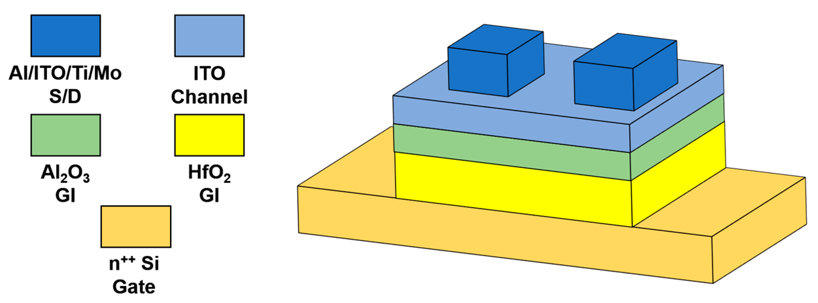
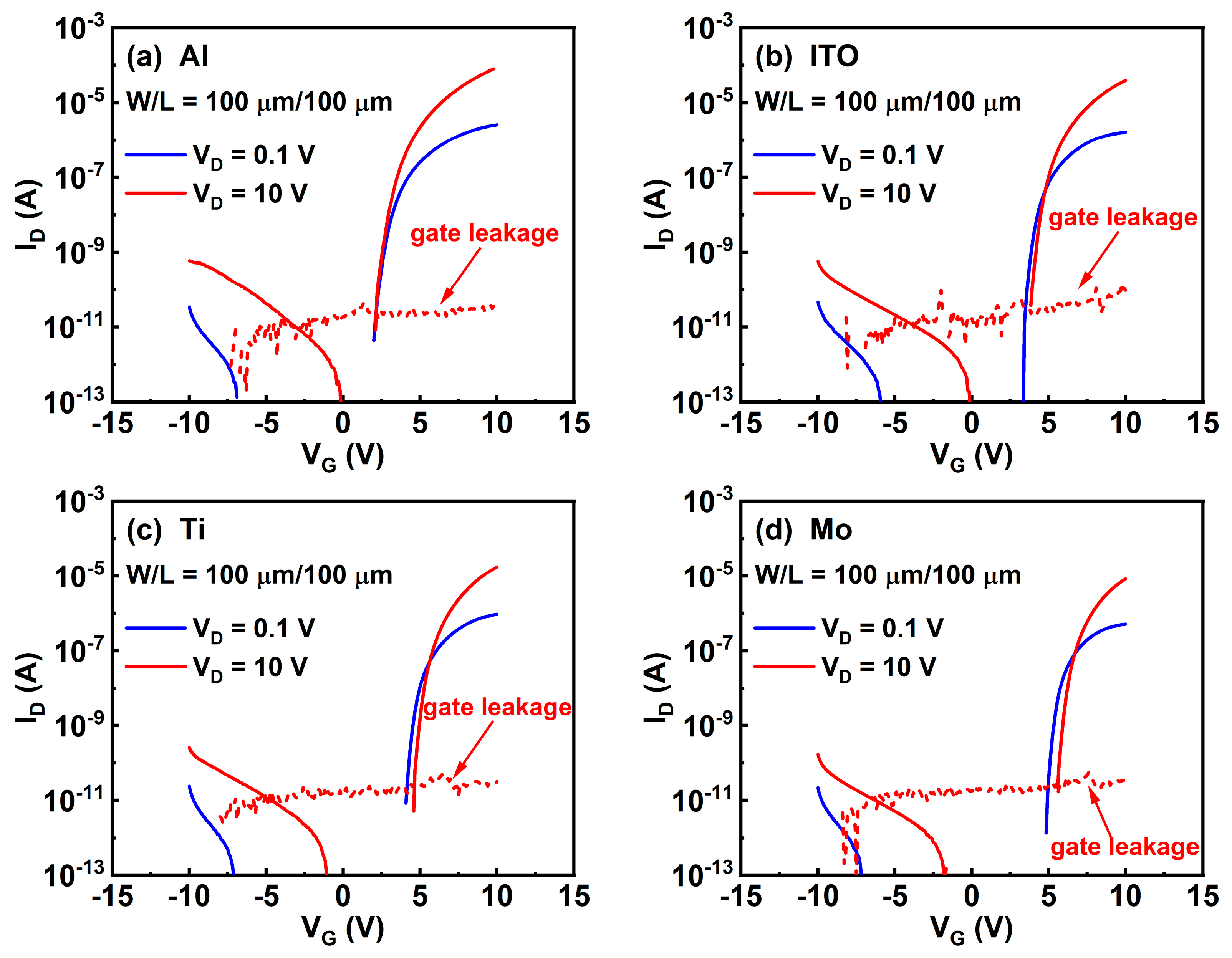
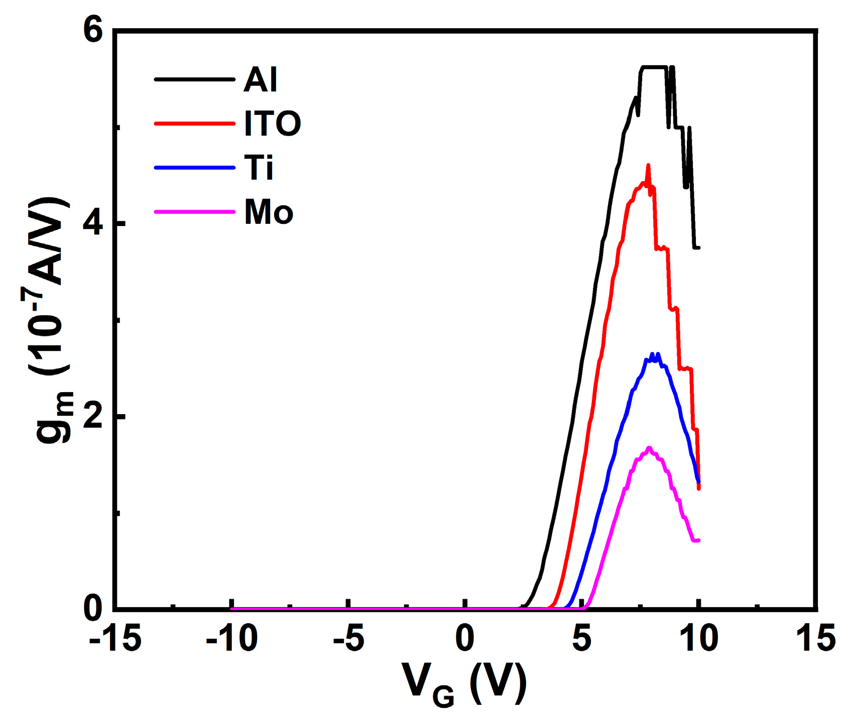

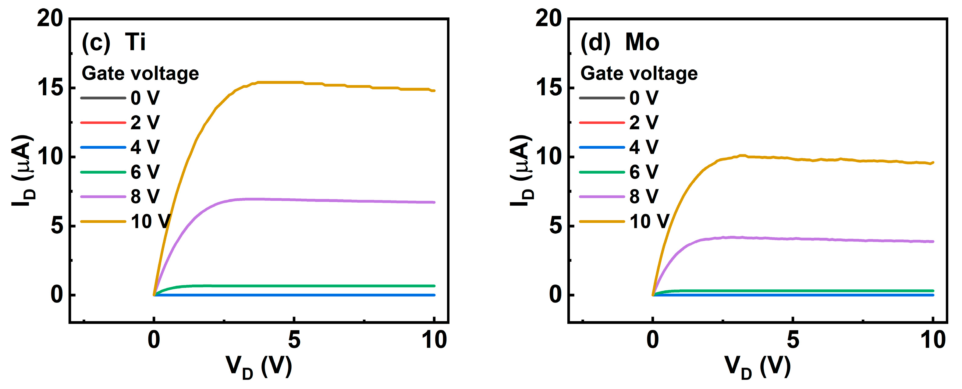
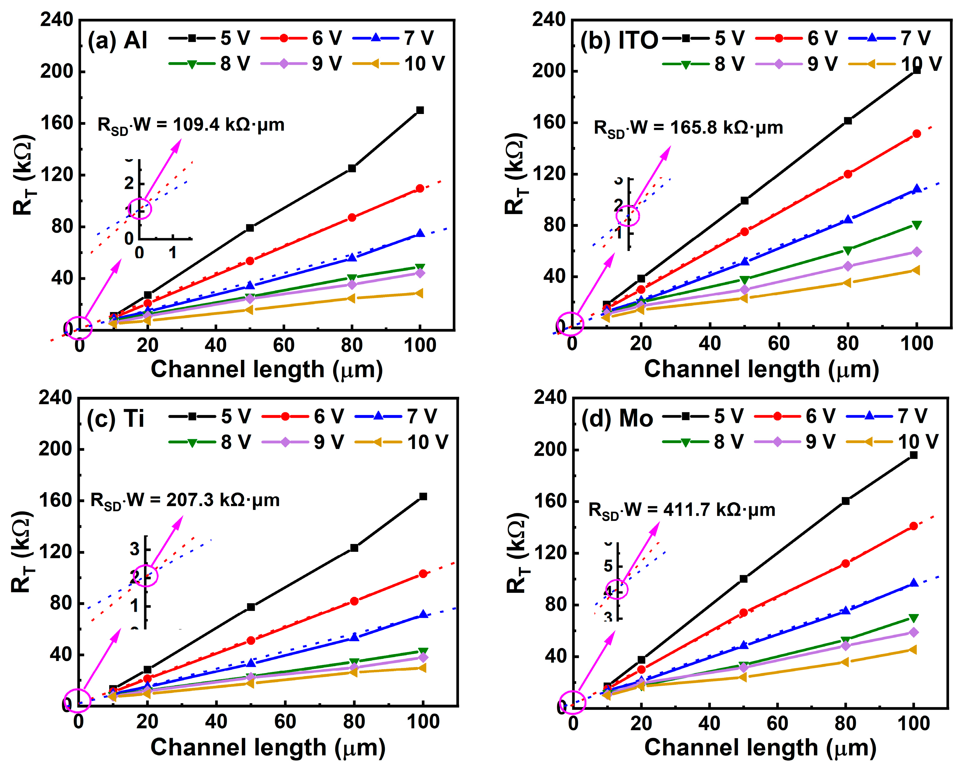
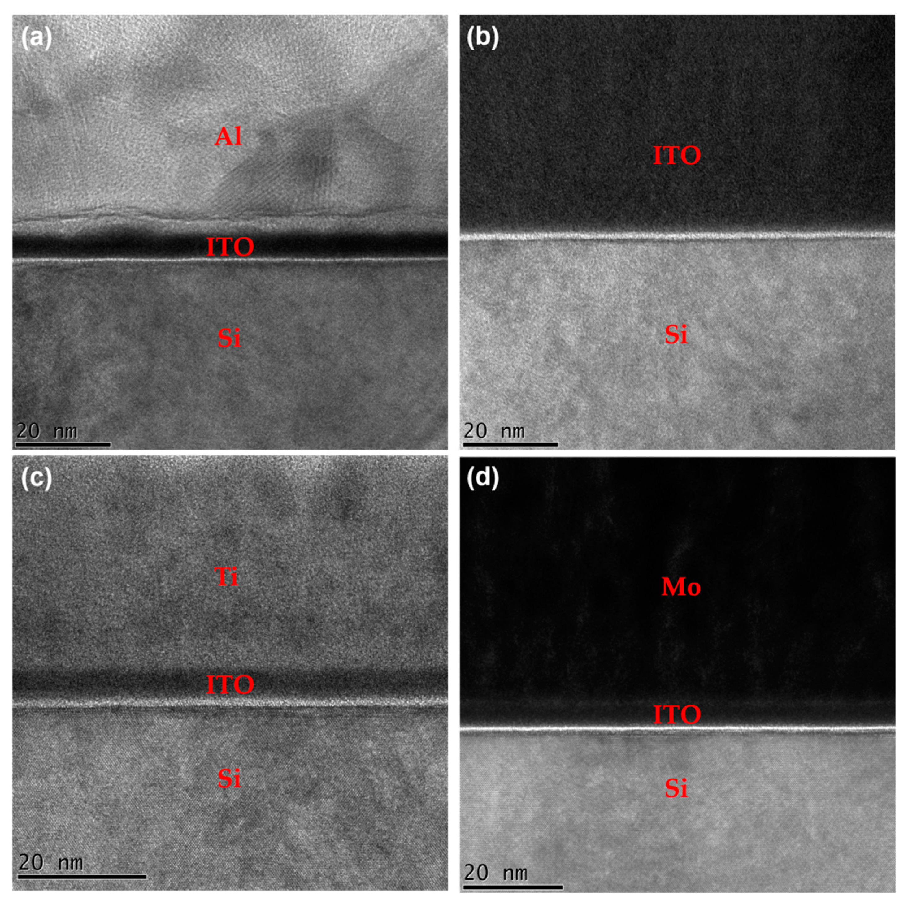
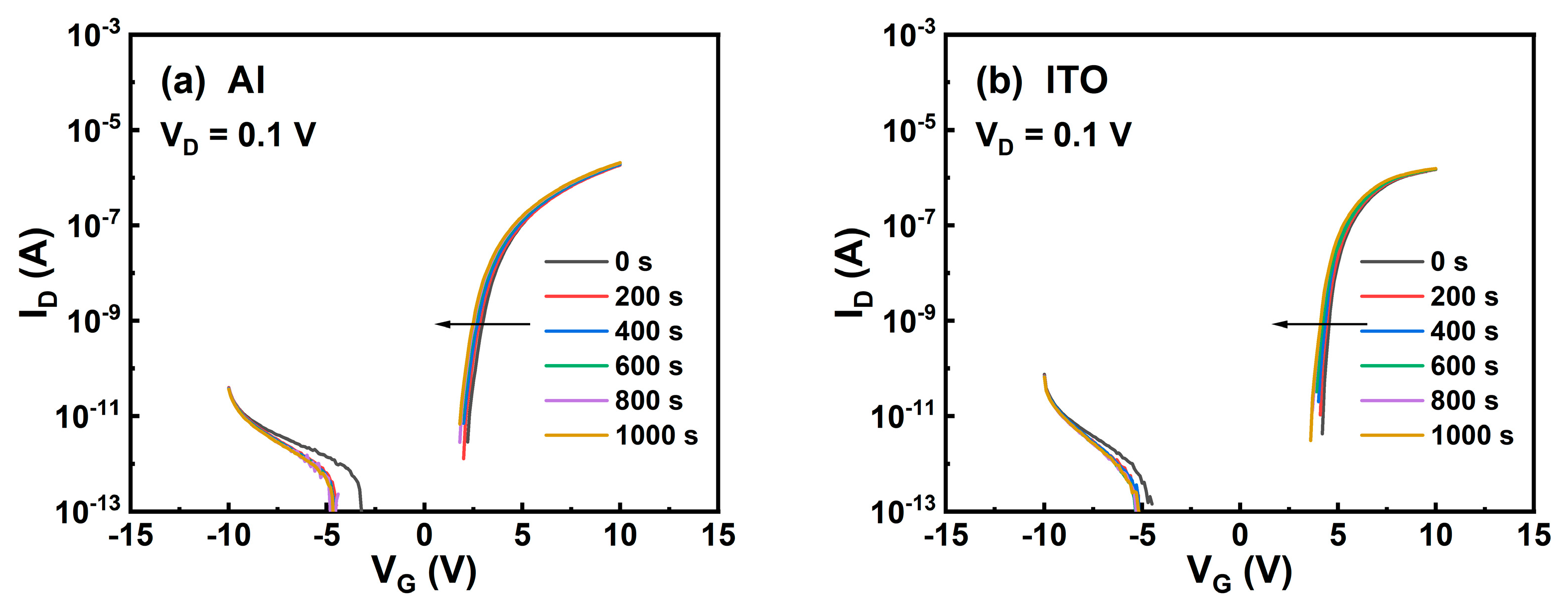

| Source/Drain | µFE (cm2/Vs) | SS (mV/Decade) | VON (V) |
|---|---|---|---|
| Al | 26.45 | 201.50 | 2.7 |
| ITO | 20.83 | 108.70 | 3.9 |
| Ti | 12.46 | 179.00 | 4.5 |
| Mo | 7.99 | 113.39 | 5.3 |
| Source/Drain | Channel | RSD × W (kΩ·μm) | µFE (cm2/Vs) | SS (mV/Decade) | VON (V) |
|---|---|---|---|---|---|
| Al [35] | IGZO | >500 | 8.1 | 1000.09 | 2.5 |
| ITO [25] | IGZO | 704 | 9.1 | 704 | ~0 |
| ITO [36] | STO | / | 5.6 | 300 | −2.4 |
| Cu/Ti [37] | IGZO | 3200 | 18.8 | / | ~2 |
| Cu [34] | IGZO | 120 | 6.3 | / | ~−3 |
| Cu/ITO [38] | IGZO | 18 | 11.5 | 200 | 1.5 |
| Mo [39] | IZTO | / | 35.25 | 210 | −0.58 |
| Au [40] | IAZO | / | 20.57 | 550 | ~0 |
| CuCrZr [41] | NdIZO | 84.5 | 32.1 | 160 | ~0 |
| Al [this work] | ITO | 109.4 | 26.45 | 201.50 | 2.7 |
Publisher’s Note: MDPI stays neutral with regard to jurisdictional claims in published maps and institutional affiliations. |
© 2022 by the authors. Licensee MDPI, Basel, Switzerland. This article is an open access article distributed under the terms and conditions of the Creative Commons Attribution (CC BY) license (https://creativecommons.org/licenses/by/4.0/).
Share and Cite
Li, Q.; Han, D.; Dong, J.; Xu, D.; Li, Y.; Wang, Y.; Zhang, X. Effects of Source/Drain Electrodes on the Performance of InSnO Thin-Film Transistors. Micromachines 2022, 13, 1896. https://doi.org/10.3390/mi13111896
Li Q, Han D, Dong J, Xu D, Li Y, Wang Y, Zhang X. Effects of Source/Drain Electrodes on the Performance of InSnO Thin-Film Transistors. Micromachines. 2022; 13(11):1896. https://doi.org/10.3390/mi13111896
Chicago/Turabian StyleLi, Qi, Dedong Han, Junchen Dong, Dengqin Xu, Yue Li, Yi Wang, and Xing Zhang. 2022. "Effects of Source/Drain Electrodes on the Performance of InSnO Thin-Film Transistors" Micromachines 13, no. 11: 1896. https://doi.org/10.3390/mi13111896
APA StyleLi, Q., Han, D., Dong, J., Xu, D., Li, Y., Wang, Y., & Zhang, X. (2022). Effects of Source/Drain Electrodes on the Performance of InSnO Thin-Film Transistors. Micromachines, 13(11), 1896. https://doi.org/10.3390/mi13111896


