Abstract
In a flexible electronic heater (FEH), periodic metal wires are often encapsulated into the soft elastic substrate as heat sources. It is of great significance to develop analytic models on transient heat conduction of such an FEH in order to provide a rapid analysis and preliminary designs based on a rapid parameter analysis. In this study, an analytic model of transient heat conduction for bi-layered FEHs is proposed, which is solved by a novel symplectic superposition method (SSM). In the Laplace transform domain, the Hamiltonian system-based governing equation for transient heat conduction is introduced, and the mathematical techniques incorporating the separation of variables and symplectic eigen expansion are manipulated to yield the temperature solutions of two subproblems, which is followed by superposition for the temperature solution of the general problem. The Laplace inversion gives the eventual temperature solution in the time domain. Comprehensive time-dependent temperatures by the SSM are presented in tables and figures for benchmark use, which agree well with their counterparts by the finite element method. A parameter analysis on the influence of the thermal conductivity ratio is also studied. The exceptional merit of the SSM is on a direct rigorous derivation without any assumption/predetermination of solution forms, and thus, the method may be extended to more heat conduction problems of FEHs with more complex structures.
1. Introduction
Electric heating devices have attracted scholarly interest due to their important engineering and medical applications during the past few decades, including resistive micro heaters [1], electrothermal pumping devices [2], shape memory polymer micro actuators for drug delivery [3], homoeothermic maintenance in small animals [4], etc. However, they are designed within rigid structures that cannot heat undevelopable curved surfaces, leading to inhomogeneous temperature distributions caused by inevitable wrinkles from non-developable designs. To resolve this problem, recent advancements in flexible electronic heaters (FEHs) have arisen.
The FEHs developed in recent years can be divided into two major categories. One is on polymers with a variety of conductive compositions, including transparent copper fiber heaters [5], metal nanowire heaters for wearable electronics applications [6], organic conductive polymers [7], carbon nanotube-based resistive heater textile [8], stretchable tattoo-like heaters with on-site temperature feedback control [9], etc. Under stretching circumstances, the electrical resistance of an FEH will increase rapidly due to the deformation of the fibers, thus leading to extraordinarily non-uniform temperatures, i.e., hot spots [5]. In addition, extremely complicated manufacturing techniques are required to produce such FEHs. The other category is encapsulating periodic metal wires into the soft elastic substrate performing as heat sources to avoid hot spots, such as kirigami-patterned wearable thermotherapy devices [10], two-dimensional serpentine configured electronics [11], three-dimensional network devices [12], multifunctional membranes in cardiac electrotherapy [13], etc. In this way, the electrical resistance of periodic metal wires will behave stably due to their flexible deformation. However, designable heat sources demand spaces to keep deformability and extensibility, resulting in different temperatures at certain positions. Since the localized high temperature will burn the tissue and it is extraordinarily hard to control the heating power, temperature uniformity is usually a key point of FEHs in engineering applications.
Great efforts have been made to achieve temperature uniformity in FEHs via periodic wire structures embedded into substrate layers. Various conductive wire heaters, which are composed of metallic nanowires [14], carbon nanotubes [15], conductive polymers [16], or hybrid materials [17], have been studied for realizing the optimal performances of the FEHs. Comparatively, metallic nanowires, e.g., Ag nanowires, not only have outstanding conductivity but also can be obtained via an uncomplicated preparation process with low cost, resulting in wide applications in FEHs. In addition to experimental studies, it is necessary to develop analytic models on the transient heat conduction of FEHs. In this way, the time-dependent temperature distribution can be rapidly predicted, and the effects of key parameters can be rapidly analyzed, which is very useful for the layout design of wire structures in FEHs. However, given the previously reported results, there have been very few studies on the analytic modeling of transient heat conduction for FEHs.
Figure 1a shows the schematic illustration of an easy-to-implement bi-layered FEH, where parallel wire heaters are sandwiched between an objective layer and an encapsulated layer. The transient heat conduction problem of such a structure is first equivalent to that of a single component due to the periodicity (Figure 1b, left and upper right). It is further simplified to a two-dimensional problem by taking a cross-section that is perpendicular to the wire in the component (Figure 1b, lower). Details appear in Section 2. The major difficulty hindering the analytic modeling of such a bi-layered transient heat conduction model is in solving the governing partial differential equations (PDEs) incorporating prescribed temperature/heat flux boundary conditions (BCs).
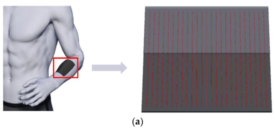
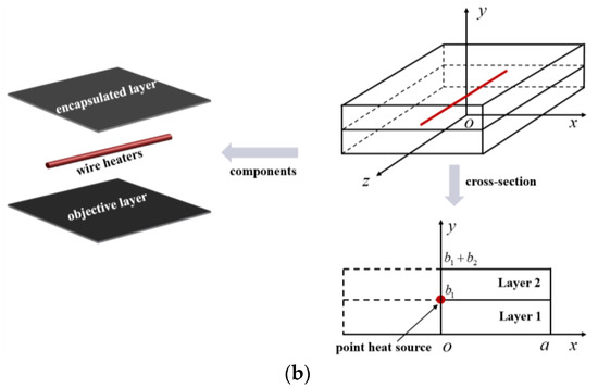
Figure 1.
Schematic illustration of (a) a bi-layered FEH with parallel wire structures integrated with human skin and (b) a bi-layered transient heat conduction model.
In recent years, we have proposed a novel analytic symplectic superposition method (SSM) that has been successfully applied to bending [18], buckling [19], and vibration [20] of plate and shell structures as well as the mechanical analysis of flexible electronics [21]. The method involves a skillful combination of the superposition method and the symplectic approach [22], which is conducted within the Hamiltonian framework in the symplectic space rather than within the Lagrangian system in the Euclidean space where the conventional analytic methods are conducted. The main idea of the SSM (Figure 2) is to transform the governing PDEs of a problem into the Hamiltonian system to establish the subproblems that can be analytically solved by the symplectic approach, and the eventual analytic solution is obtained according to the equivalence between the general problem and the superposition of the subproblems.

Figure 2.
Flowchart of the solution procedure for the SSM.
Compared with the conventional methods, the exceptional merit of SSM is the inherent rigorous derivation without any assumption and pre-determination of solution forms, which enables it to serve as a general method for new analytic solutions. Although the main applications of the SSM have been on the mechanical problems of structures, it may find access to some new issues that are physically different from the mechanical problems.
In this study, we make an SSM-based successful attempt to achieve the transient heat conduction analysis for bi-layered FEHs. The governing equation in the Hamiltonian system is introduced in Section 2, where the symplectic eigenproblems are generated by the separation of variables in the symplectic space. In Section 3, the basic solution procedure of subproblems is presented, and the eventual solution is obtained by superposition. The convergent time-dependent temperature results obtained by the SSM are given in Section 4, with the verification by the finite element method (FEM). With the transient solution, the steady-state results are also revealed, and the effect of the thermal conductivity ratio is discussed. Conclusions are drawn in Section 5.
2. Governing Equation for Bi-Layered Transient Heat Conduction within the Hamiltonian Framework
As is shown in Figure 1b, lower, a two-dimensional half model is considered for a single component due to the symmetry with respect to the oy axis, with the entire dimensions along ox and oy axes being and , respectively. The thickness of Layer 1 (the bottom objective layer) is and that of Layer 2 (the top encapsulated layer) is . The wire heat source is modeled as a point heat source (with a half heat source intensity) in the cross-section, as indicated by the semicircular red dot at . The governing transient heat conduction equation is written as [23]
Here, the quantities with a subscript (=1 or 2) represent those for Layer . is the temperature increment function, is the heat source, is time, is the thermal diffusivity with being the thermal conductivity, being the density, and being the specific heat capacity.
The BCs at the upper and lower surfaces yield
In this study, it comes to either Dirichlet type, with and , or Neumann type, with and . The left and right sides are subjected to adiabatic BCs due to the symmetry with respect to the oy axis and the periodicity along the ox axis, respectively.
The Laplace transform of a real function , with for , and its inversion are defined as [24]
with (), where is the imaginary unit. is arbitrary but greater than the real parts of all the singularities of .
The governing equation and BCs are converted into the Laplace transform domain:
where the variables with an overbar represent those in the Laplace transform domain and s represents the Laplace transform parameter. Introduce the Lagrangian function [25]:
where the over dot indicates the partial derivative about y. Based on the principle of the least action for the transient heat conduction process [26], we acquire
It is noted that for the transient heat conduction process, the entransy dissipation rate closely connects to the integral of the convolution of heat flux and negative temperature gradient over the time and space domain, whose convolution integral consists of the influence of the time evolution. In addition, the transient heat conduction process includes both the dissipating and non-dissipating processes, and thus, its variational function could include both the dissipating and non-dissipating terms [27,28], as depicted in Equation (5).
Defining
its dual variable can be obtained by Legendre transform, yielding
The Hamiltonian function is introduced according to Equations (7) and (8) as
with and . Accordingly, the variation of Equation (9), yields the following Hamiltonian-system equation
where is the state vector, is the vector concerning the heat source, and is the point heat source with a constant heat source intensity and the Dirac delta function .
is the Hamiltonian operator matrix that satisfies , where is a symplectic matrix [22].
Separating the variables in the symplectic space as , where is a vector depending only on x, and is a function depending only on y, we have
where is a non-zero eigenvalue, and is the corresponding eigenvector. The characteristic equation of the second half of Equation (12) is
with the roots
and
The general temperature solution in the Laplace transform domain is therefore
where and are coefficients undetermined hitherto.
3. New Analytic Solution by the SSM
Since the main purpose of this study is to provide an SSM-based analytic model of transient heat conduction for bi-layered FEHs, a general problem with an arbitrarily positioned point heat source at in Layer 1 and an arbitrarily positioned point heat source at in Layer 2 is constructed (Figure 3a). In the following, the analytic solution will be derived within the framework of the Hamiltonian system via the solution procedure of the SSM in Figure 3, where two subproblems are given to establish the equivalence to the general problem. The basic systems of the two subproblems are both within a rectangular domain with zero heat flux, i.e., adiabatic BCs, on opposite edges at and .

Figure 3.
SSM procedure for bi-layered transient heat conduction with two arbitrarily positioned point heat sources. (a) General problem. (b) Subproblem for Layer 1. (c) Subproblem for Layer 2.
In Layer 1 (Figure 3b), the heat flux BCs should be satisfied: , which yields and , leading to
The eigenvalues are thus
The corresponding eigenvectors are
It is necessary to mention that and are symplectically conjugated (i.e., ), while any other combinations of two eigenvectors are symplectically orthogonal [22]. Moreover, we have constant eigenvalues and from Equation (18) when ; thus, the corresponding eigenvectors are
Since all eigenvectors have been obtained for the Layer 1 problem, the state vector can be expanded according to the symplectic orthogonality and conjugacy, yielding
where
Substituting Equation (21) into Equation (10) yields
From the second of Equation (12), we have
where . The vector concerning the heat source can be expanded by the symplectic eigenvectors, i.e.,
where is the column matrix of the expansion coefficients. Taking Equations (24) and (25) into Equation (23), we have
i.e.,
Multiplying both sides of Equation (25) by with integration concerning x over , i.e.,
we obtain
Substituting Equation (29) into Equation (27), we obtain
where , , , and are undetermined coefficients and is the Heaviside function. With the BCs at the bottom surface attached to human skin and the interface between Layer 1 and Layer 2:
the temperature solution in Layer 1 (Figure 3b) in the Laplace transform domain is obtained as
where , , , , , , , , , , and .
Following the same logic as described above, with the BCs at the top surface exposed to air and the interface between Layer 1 and Layer 2:
the temperature solution in Layer 2 (Figure 3c) in the Laplace transform domain is obtained as
where , , , , , , and .
Both the temperature and heat flux should be continuous at the interface at . The continuity of heat flux at has been satisfied, as revealed in Equations (31) and (33) where the same heat flux expression holds for Layer 1 and Layer 2. The continuity of temperature requires
By Equation (35), the coefficients and are determined, and the analytic solution can be eventually given in the Laplace transform domain as
It should be pointed out that an explicit expression of the inverse Laplace transform is strikingly complicated, and thus, it is not presented here.
4. Comprehensive Benchmark Results
To provide comprehensive numerical and graphical results as benchmarks for further structural designs, the analytic transient heat conduction results of bi-layered FEHs are given by the SSM with verification by the FEM. The considered circumstances are given with the following parameters: , , , , , , , , and . The BCs for Case 1 are set, with the top surface subjected to room temperature and the bottom surface subjected to body temperature . The point heat source corresponds to and at . The BCs for Case 2 are given with the top and bottom surfaces subjected to , and the point heat source corresponds to and . The FEM is used via the software package ABAQUS with the four-node linear heat transfer quadrilateral shell element DC2D4 and the uniform mesh size of a/100 to achieve the convergent numerical solutions.
As revealed by the temperature results marked in bold in Table 1, rapid convergence is achieved such that dozens of series terms (20 at most) are enough to realize the accuracy to the last significant digit of five, and these results are justified by comparison with those by the FEM due to the lack of available analytic solutions. Therefore, 20 series terms are taken throughout this study.

Table 1.
Convergence study for the present temperature solutions (°C) at typical locations when t = 15.0 s.
The temperature results at typical locations within a broad time range are tabulated in Table 2 and Table 3. The comparison shows that all the present results agree quite well with those by the FEM, which confirms the validity and accuracy of the SSM.

Table 2.
FEM-validated temperature solutions (oC) at different times for Case 1.

Table 3.
FEM-validated temperature solutions (°C) at different times for Case 2.
To give more intuitive results, Figure 4 plots the contours of temperature distribution at different times for a more realistic Case 1 followed by comparison with the FEM, where satisfactory agreement is also observed. In addition, the time-dependent temperatures at a typical location, (a/2, a/2), are plotted in Figure 5, with the inset showing the temperature distribution under steady state when t > 9.0 s.
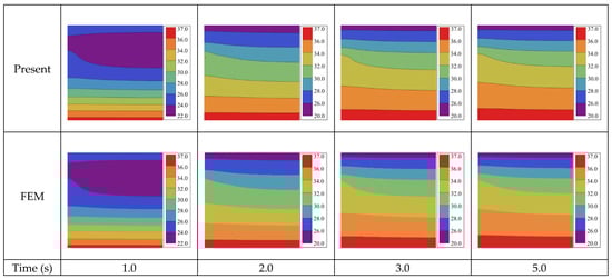
Figure 4.
Temperature distribution (°C) for Case 1 on bi-layered transient heat conduction with a point heat source.
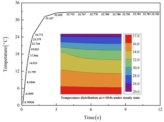
Figure 5.
Time-dependent temperatures for Case 1 at (a/2, a/2), with the inset showing the temperature distribution under steady state.
To further study the influence of thermal properties on the heat conduction behavior, a parameter analysis for Case 1 is conducted by changing the thermal conductivity but keeping constant, as shown in Figure 6. It is found that the larger the thermal conductivity ratio is, the faster the steady state is reached, which indicates a speed-up of thermotherapy. On the other hand, a larger corresponds to higher temperatures in Layer 1, which helps raise the temperature near human skin.
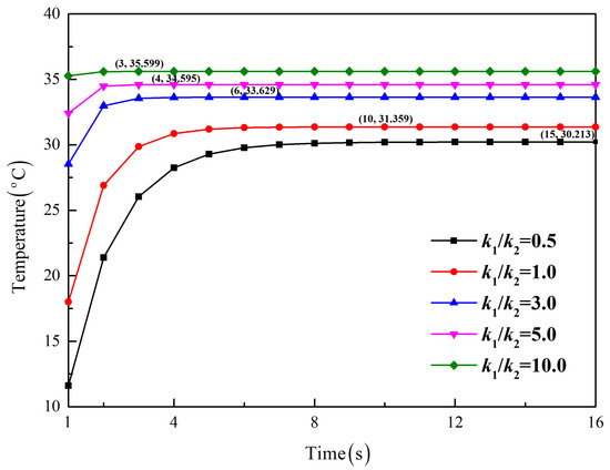
Figure 6.
Influence of the thermal conductivity ratio on time-dependent temperatures for Case 1 at (a/2, a/2).
5. Conclusions
In this study, an analytic model of transient heat conduction by symplectic superposition is established for bi-layered FEHs and is well verified by the FEM modeling. By converting the problems in the Laplace transform domain into the Hamiltonian system, the mathematical techniques such as separation of variables and symplectic eigen expansion become available for deriving some new analytic solutions. The high accuracy and rapid convergence of the SSM are well confirmed by the numerical results as compared with the FEM results shown in tables and figures. The time-dependent temperature results, including the steady-state results, and the effect of thermal conductivity ratio on heat conduction have also been investigated. The developed analytic model provides a theoretical basis for transient heat conduction analysis of bi-layered FEHs, and it may be extended to more complicated problems, such as those of multi-layered FEHs and orthotropic FEHs. It is also worth mentioning that although the present solution does not involve Robin-type BCs, the SSM may be extended to heat conduction problems under such BCs as well.
Author Contributions
Conceptualization, R.L.; methodology, R.L., B.W., D.X. and S.X.; formal analysis, D.X. and F.M.; data curation, S.X. and F.M.; software, S.X. and F.M.; writing-original draft, D.X.; writing-review and editing, R.L. and B.W.; supervision, R.L.; funding acquisition, R.L. and B.W. All authors have read and agreed to the published version of the manuscript.
Funding
This research was funded by the National Natural Science Foundation of China (grants 12022209, 11972103, and U21A20429) and Fundamental Research Funds for the Central Universities (grant DUT21LAB124).
Data Availability Statement
The data presented in this study are available on reasonable request from the corresponding author.
Conflicts of Interest
The authors declare no conflict of interest.
References
- Kwon, J.; Hong, S.; Kim, G.; Suh, Y.D.; Lee, H.; Choo, S.; Lee, D.; Kong, H.; Yeo, J.; Ko, S.H. Digitally patterned resistive micro heater as a platform for zinc oxide nanowire based micro sensor. Appl. Surf. Sci. 2018, 447, 1–7. [Google Scholar] [CrossRef]
- Williams, S.J.; Green, N.G. Electrothermal pumping with interdigitated electrodes and resistive heaters. Electrophoresis 2015, 36, 1681–1689. [Google Scholar] [CrossRef]
- Zainal, M.A.; Ahmad, A.; Ali, M.S.M. Frequency-controlled wireless shape memory polymer microactuator for drug delivery application. Biomed. Microdevices 2017, 19, 8. [Google Scholar] [CrossRef]
- Kersemans, V.; Gilchrist, S.; Allen, P.D.; Beech, J.S.; Kinchesh, P.; Vojnovic, B.; Smart, S.C. A resistive heating system for homeothermic maintenance in small animals. Magn. Reson. Imaging 2015, 33, 847–851. [Google Scholar] [CrossRef]
- Jo, H.S.; An, S.; Lee, J.G.; Park, H.G.; Al-Deyab, S.S.; Yarin, A.L.; Yoon, S.S. Highly flexible, stretchable, patternable, transparent copper fiber heater on a complex 3D surface. NPG Asia Mater. 2017, 9, e347. [Google Scholar] [CrossRef]
- Hong, S.; Lee, H.; Lee, J.; Kwon, J.; Han, S.; Suh, Y.D.; Cho, H.; Shin, J.; Yeo, J.; Ko, S.H. Highly stretchable and transparent metal nanowire heater for wearable electronics applications. Adv. Mater. 2015, 27, 4744–4751. [Google Scholar] [CrossRef]
- Oh, J.Y.; Kim, S.; Baik, H.K.; Jeong, U. Conducting polymer dough for deformable electronics. Adv. Mater. 2016, 28, 4455–4461. [Google Scholar] [CrossRef]
- Li, Y.; Zhang, Z.; Li, X.; Zhang, J.; Lou, H.; Shi, X.; Cheng, X.; Peng, H. A smart, stretchable resistive heater textile. J. Mater. Chem. C 2017, 5, 41–46. [Google Scholar] [CrossRef]
- Stier, A.; Halekote, E.; Mark, A.; Qiao, S.; Yang, S.; Diller, K.; Lu, N. Stretchable tattoo-like heater with on-site temperature feedback control. Micromachines 2018, 9, 170. [Google Scholar] [CrossRef]
- Jang, N.S.; Kim, K.H.; Ha, S.H.; Jung, S.H.; Lee, H.M.; Kim, J.M. Simple approach to high-performance stretchable heaters based on kirigami patterning of conductive paper for wearable thermotherapy applications. ACS Appl. Mater. Interfaces 2017, 9, 19612–19621. [Google Scholar] [CrossRef]
- Li, K.; Cheng, X.; Zhu, F.; Li, L.; Xie, Z.; Luan, H.; Wang, Z.; Ji, Z.; Wang, H.; Liu, F.; et al. A generic soft encapsulation strategy for stretchable electronics. Adv. Funct. Mater. 2019, 29, 1806630. [Google Scholar] [CrossRef]
- Yan, D.; Chang, J.; Zhang, H.; Liu, J.; Song, H.; Xue, Z.; Zhang, F.; Zhang, Y. Soft three-dimensional network materials with rational bio-mimetic designs. Nat. Commun. 2020, 11, 1180. [Google Scholar] [CrossRef] [PubMed]
- Xu, L.; Gutbrod, S.R.; Ma, Y.; Petrossians, A.; Liu, Y.; Webb, R.C.; Fan, J.A.; Yang, Z.; Xu, R.; Whalen, J.J., III; et al. Materials and fractal designs for 3D multifunctional integumentary membranes with capabilities in cardiac electrotherapy. Adv. Mater. 2015, 27, 1731–1737. [Google Scholar] [CrossRef] [PubMed]
- Cai, Y.; Piao, X.; Yao, X.; Nie, E.; Zhang, Z.; Sun, Z. A facile method to prepare silver nanowire transparent conductive film for heaters. Mater. Lett. 2019, 249, 66–69. [Google Scholar] [CrossRef]
- Yoon, Y.H.; Song, J.W.; Kim, D.; Kim, J.; Park, J.K.; Oh, S.K.; Han, C.S. Transparent film heater using single-walled carbon nanotubes. Adv. Mater. 2007, 19, 4284–4287. [Google Scholar] [CrossRef]
- Gueye, M.N.; Carella, A.; Demadrille, R.; Simonato, J.P. All-polymeric flexible transparent heaters. ACS Appl. Mater. Interfaces 2017, 9, 27250–27256. [Google Scholar] [CrossRef]
- Ji, S.; He, W.; Wang, K.; Ran, Y.; Ye, C. Thermal response of transparent silver nanowire/ PEDOT: PSS film heaters. Small 2014, 10, 4951–4960. [Google Scholar] [CrossRef]
- Zheng, X.; Sun, Y.; Huang, M.; An, D.; Li, P.; Wang, B.; Li, R. Symplectic superposition method-based new analytic bending solutions of cylindrical shell panels. Int. J. Mech. Sci. 2019, 152, 432–442. [Google Scholar] [CrossRef]
- Zheng, X.; Ni, Z.; Xu, D.; Wang, Z.; Liu, M.; Li, Y.; Du, J.; Li, R. New analytic buckling solutions of non-Lévy-type cylindrical panels within the symplectic framework. Appl. Math. Model. 2021, 98, 398–415. [Google Scholar] [CrossRef]
- Xu, D.; Ni, Z.; Li, Y.; Hu, Z.; Tian, Y.; Wang, B.; Li, R. On the symplectic superposition method for free vibration of rectangular thin plates with mixed boundary constraints on an edge. Theor. Appl. Mech. Lett. 2021, 11, 100293. [Google Scholar] [CrossRef]
- Li, R.; Li, M.; Su, Y.; Song, J.; Ni, X. An analytical mechanics model for the island-bridge structure of stretchable electronics. Soft Matter 2013, 9, 8476. [Google Scholar] [CrossRef]
- Yao, W.; Zhong, W.; Lim, C. Symplectic Elasticity; World Scientific: Singapore, 2009. [Google Scholar]
- Fourier, J.B.J. The Analytical Theory of Heat; The University Press: Cambridge, UK, 1878. [Google Scholar]
- Honig, G.; Hirdes, U. A method for the numerical inversion of Laplace transforms. Comput. Appl. Math. 1984, 10, 113–132. [Google Scholar] [CrossRef]
- Xu, C.; Rong, D.; Zhou, Z.; Xu, X. A novel Hamiltonian-based method for two-dimensional transient heat conduction in a rectangle with specific mixed boundary conditions. J. Therm. Sci. Technol. 2017, 12, JTST0021. [Google Scholar] [CrossRef][Green Version]
- Hua, Y.; Zhao, T.; Guo, Z. Optimization of the one-dimensional transient heat conduction problems using extended entransy analyses. Int. J. Heat Mass Transf. 2018, 116, 166–172. [Google Scholar] [CrossRef]
- Zhao, T.; Ai, W.; Ma, H.; Liang, Z.; Chen, Q. Integral identification of fluid specific heat capacity and heat transfer coefficient distribution in heat exchangers based on multiple-case joint analysis. Int. J. Heat Mass Transf. 2022, 185, 122394. [Google Scholar] [CrossRef]
- Hua, Y.; Zhao, T.; Guo, Z. Irreversibility and Action of the Heat Conduction Process. Entropy 2018, 20, 206. [Google Scholar] [CrossRef]
Publisher’s Note: MDPI stays neutral with regard to jurisdictional claims in published maps and institutional affiliations. |
© 2022 by the authors. Licensee MDPI, Basel, Switzerland. This article is an open access article distributed under the terms and conditions of the Creative Commons Attribution (CC BY) license (https://creativecommons.org/licenses/by/4.0/).