
Dynamic Performance of Partially Orifice Porous Aerostatic Thrust Bearing


Abstract
:1. Introduction
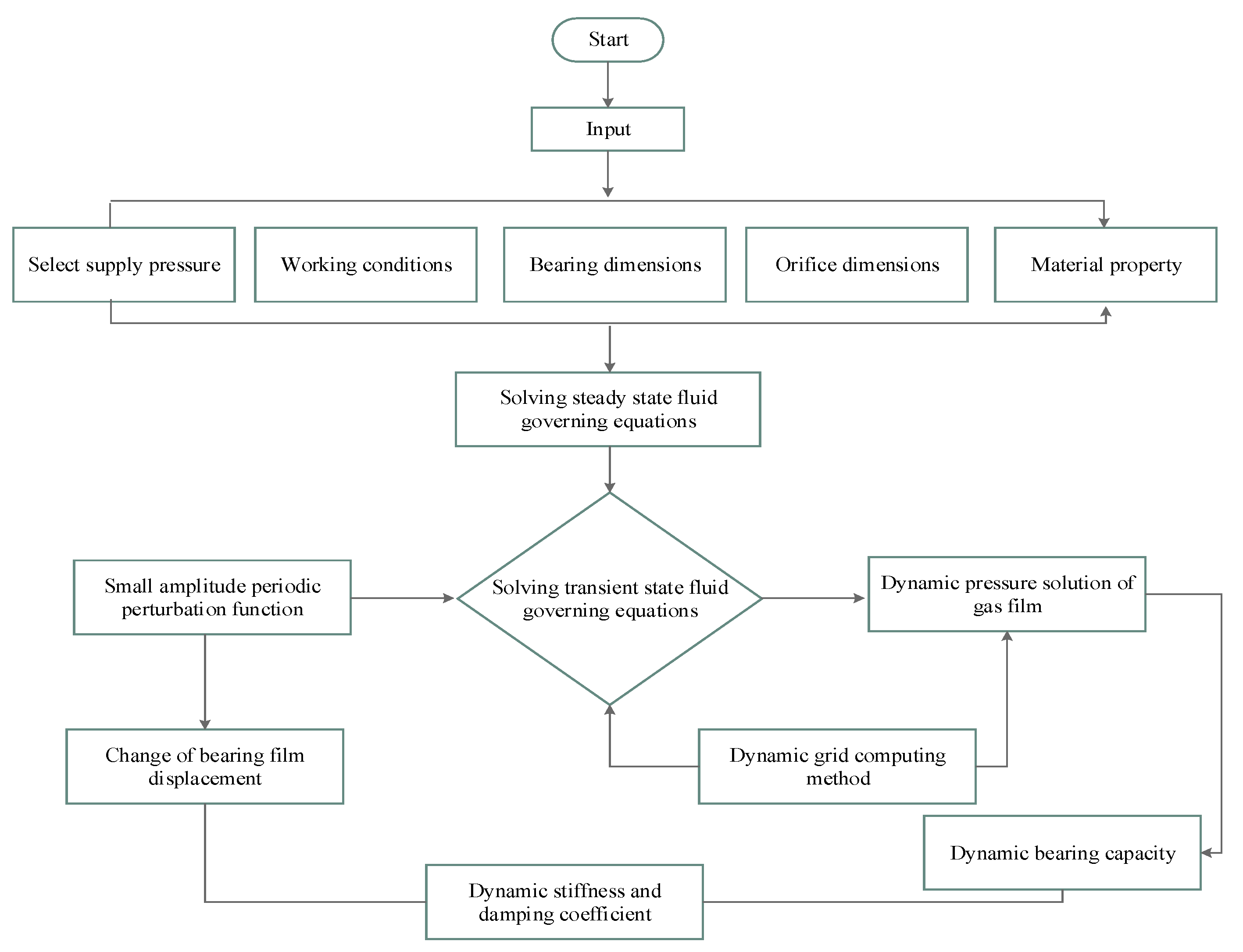
2. Methodologies
2.1. CFD Base Dynamic Grid Calculation Method
2.2. Fluid Control Equation
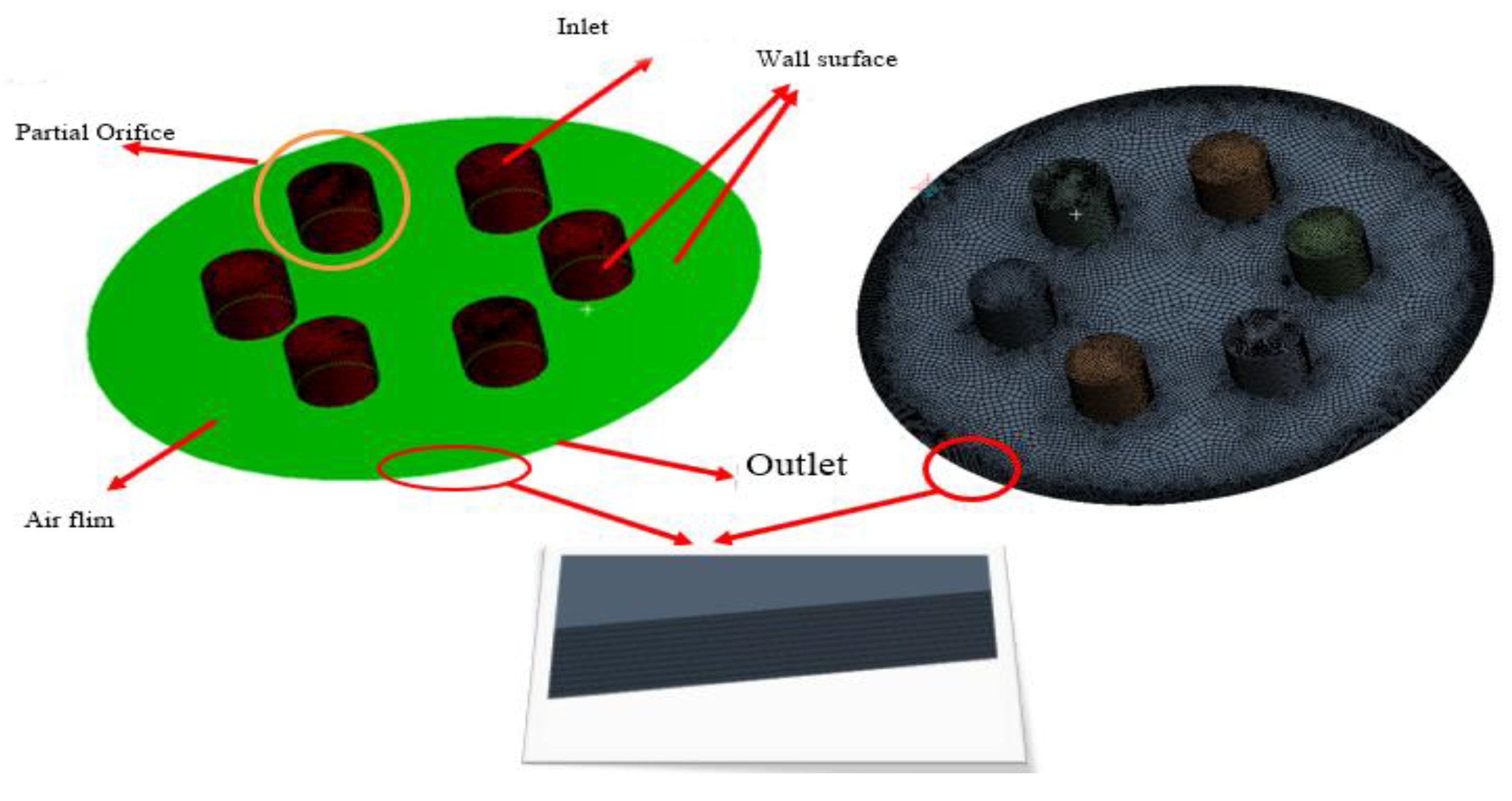
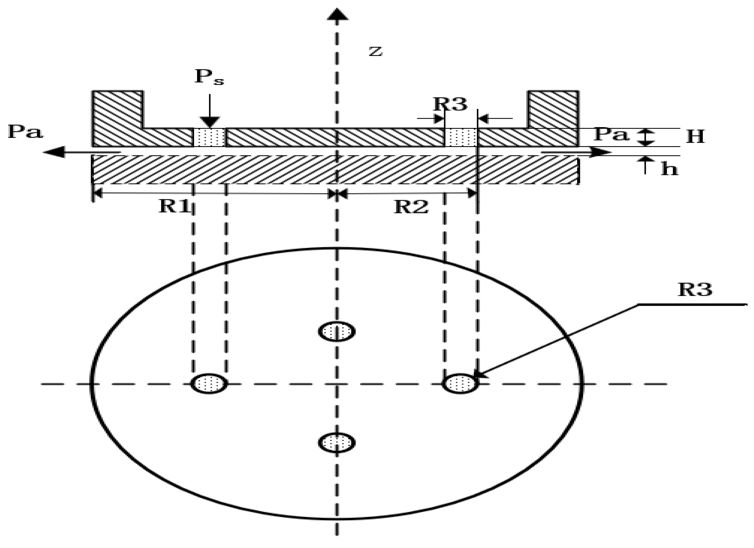
2.3. Computational Models and Grids
2.4. Dynamic Grid Method
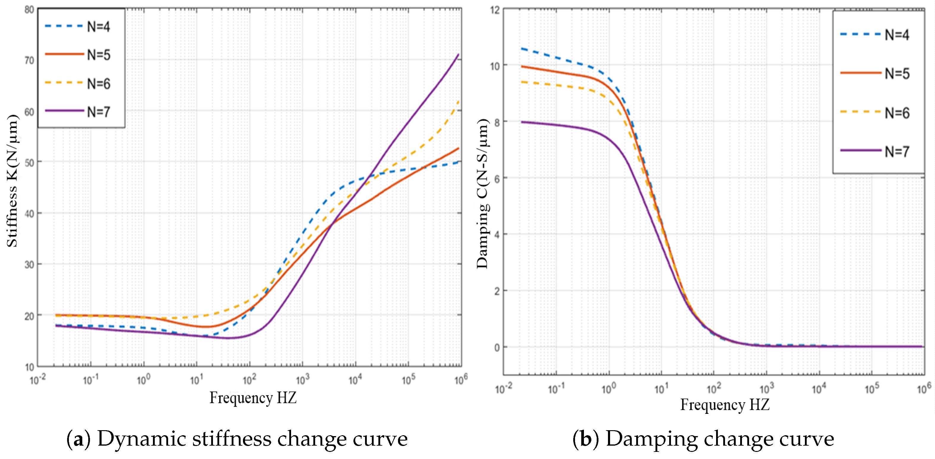
3. Dynamic Stiffness and Damping Characteristics Analysis
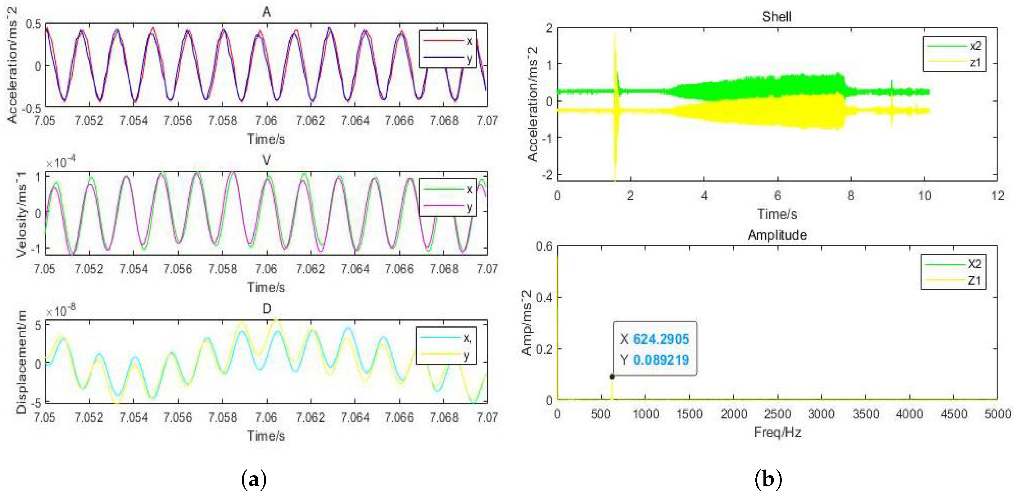
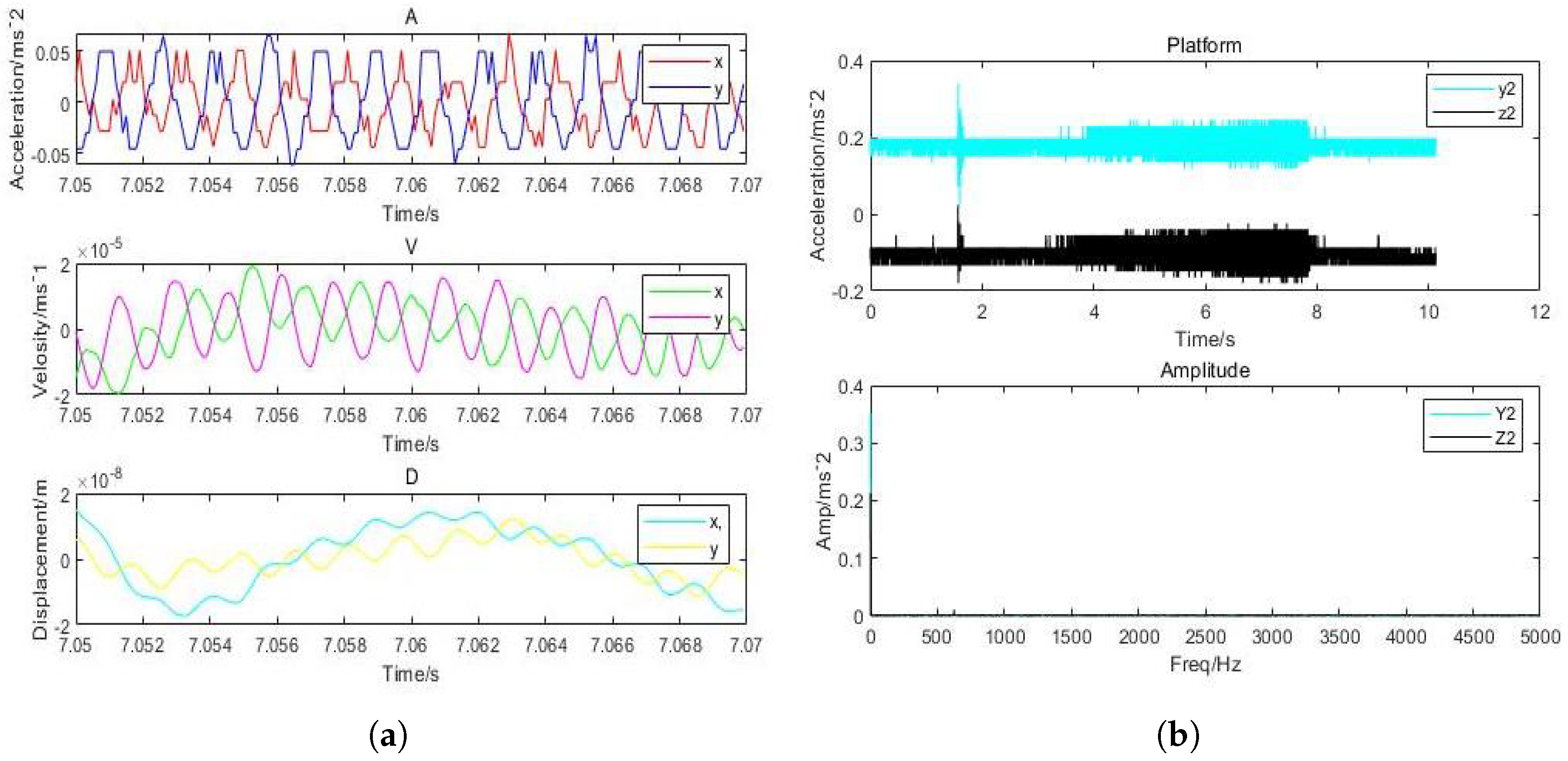
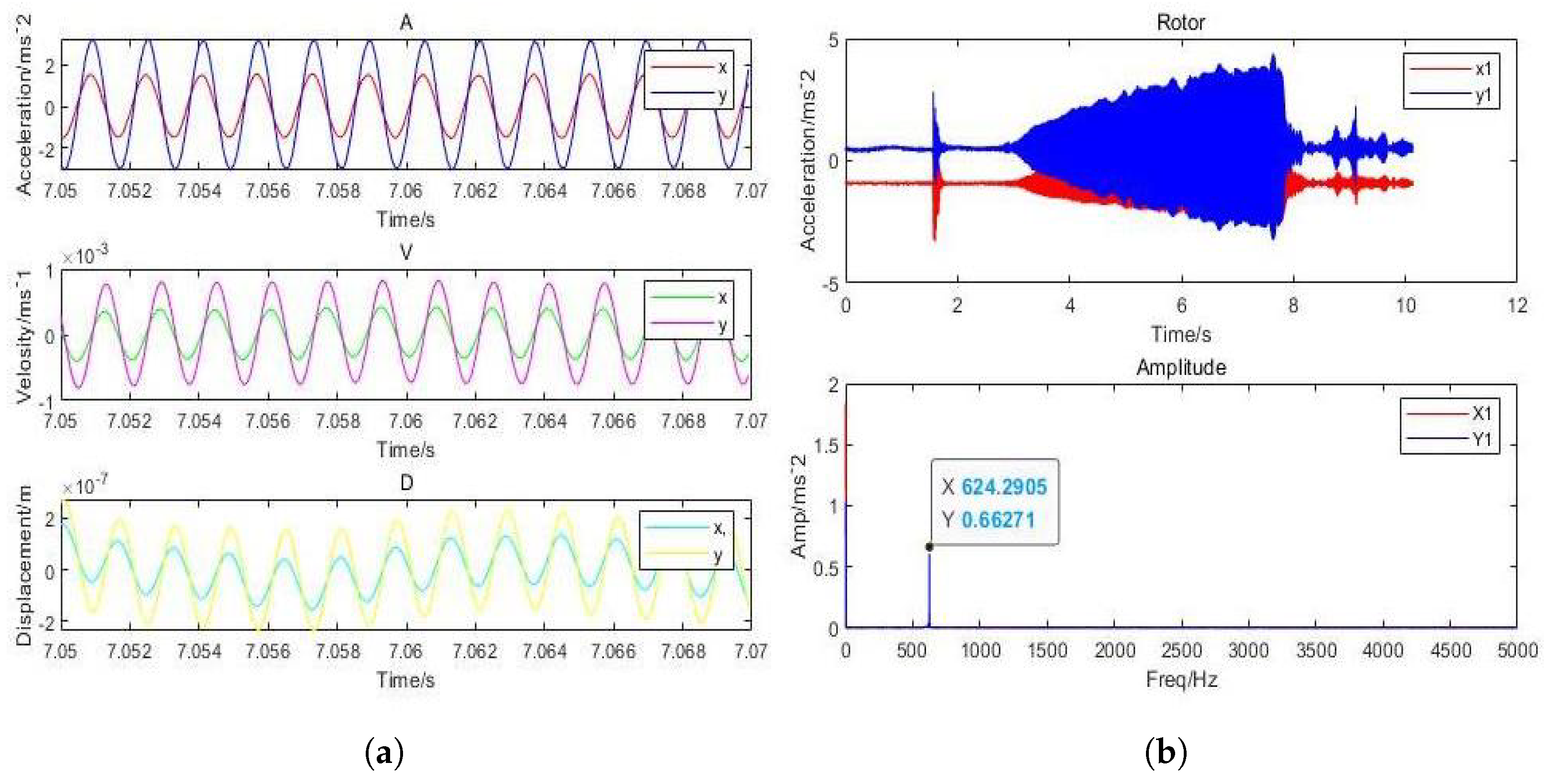
Dynamic Mechanical Properties of Gas Film
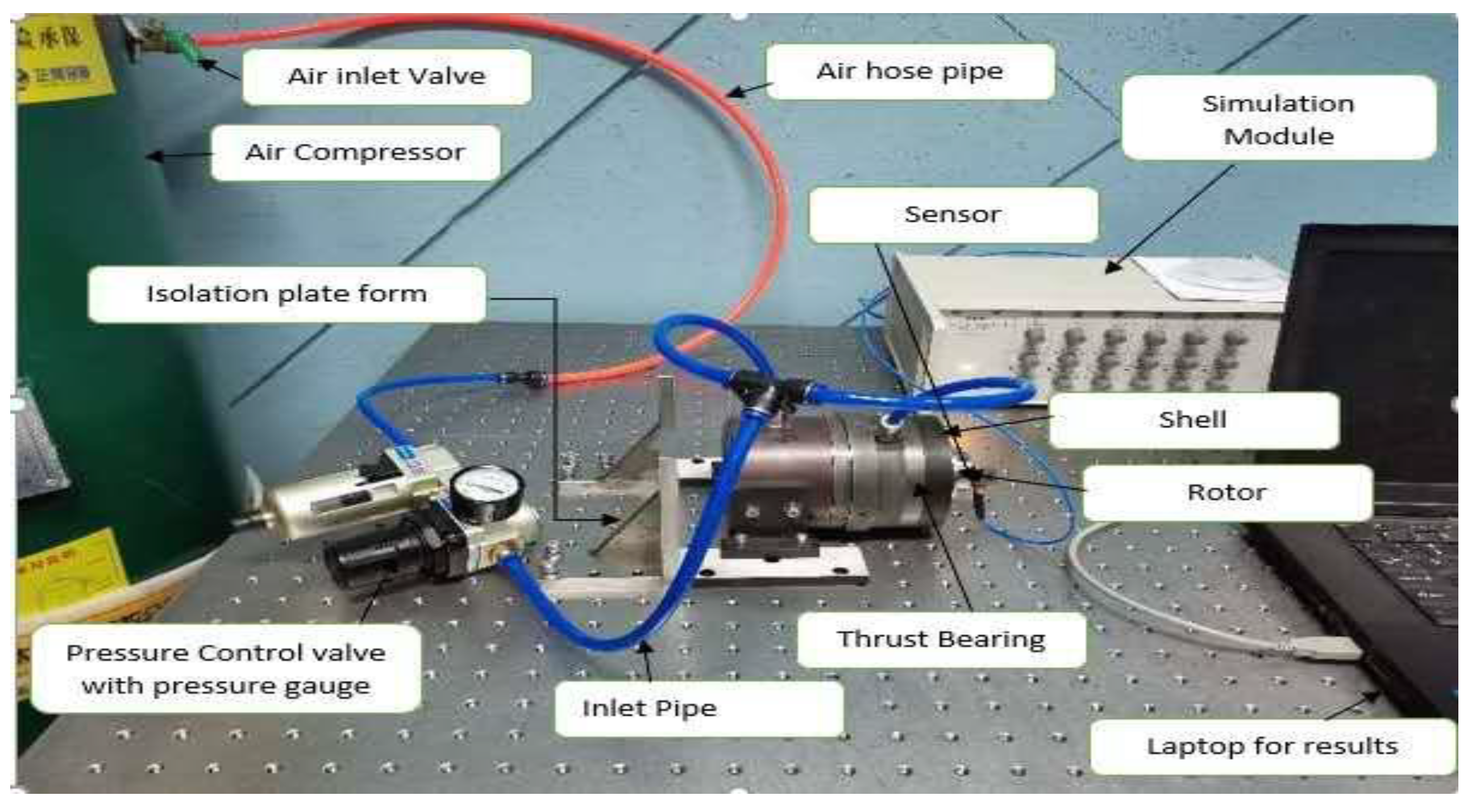
4. Experimental Setup
5. Analysis of Factors Influencing Damping, Static, and Dynamic Stiffness Characteristics
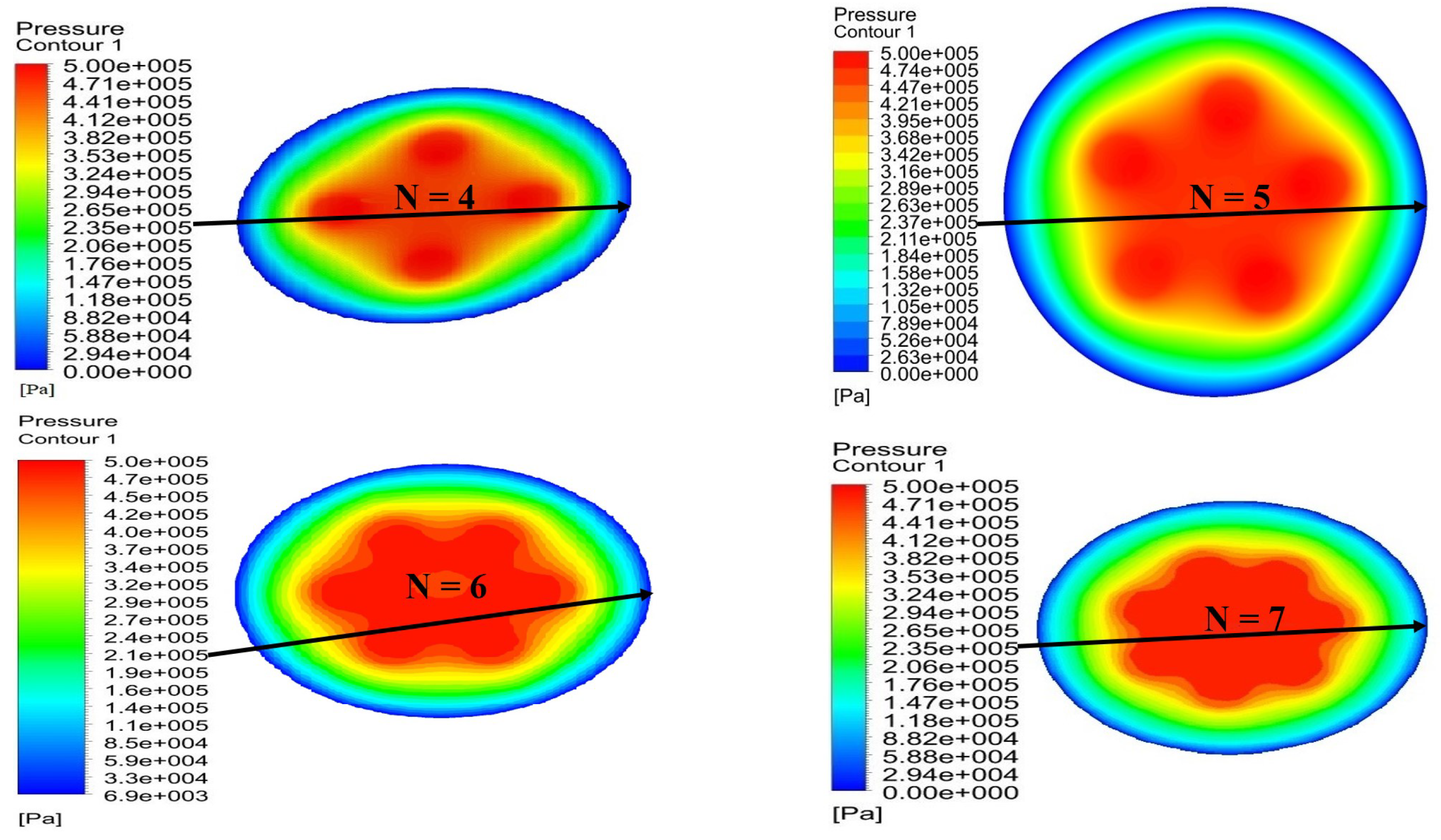
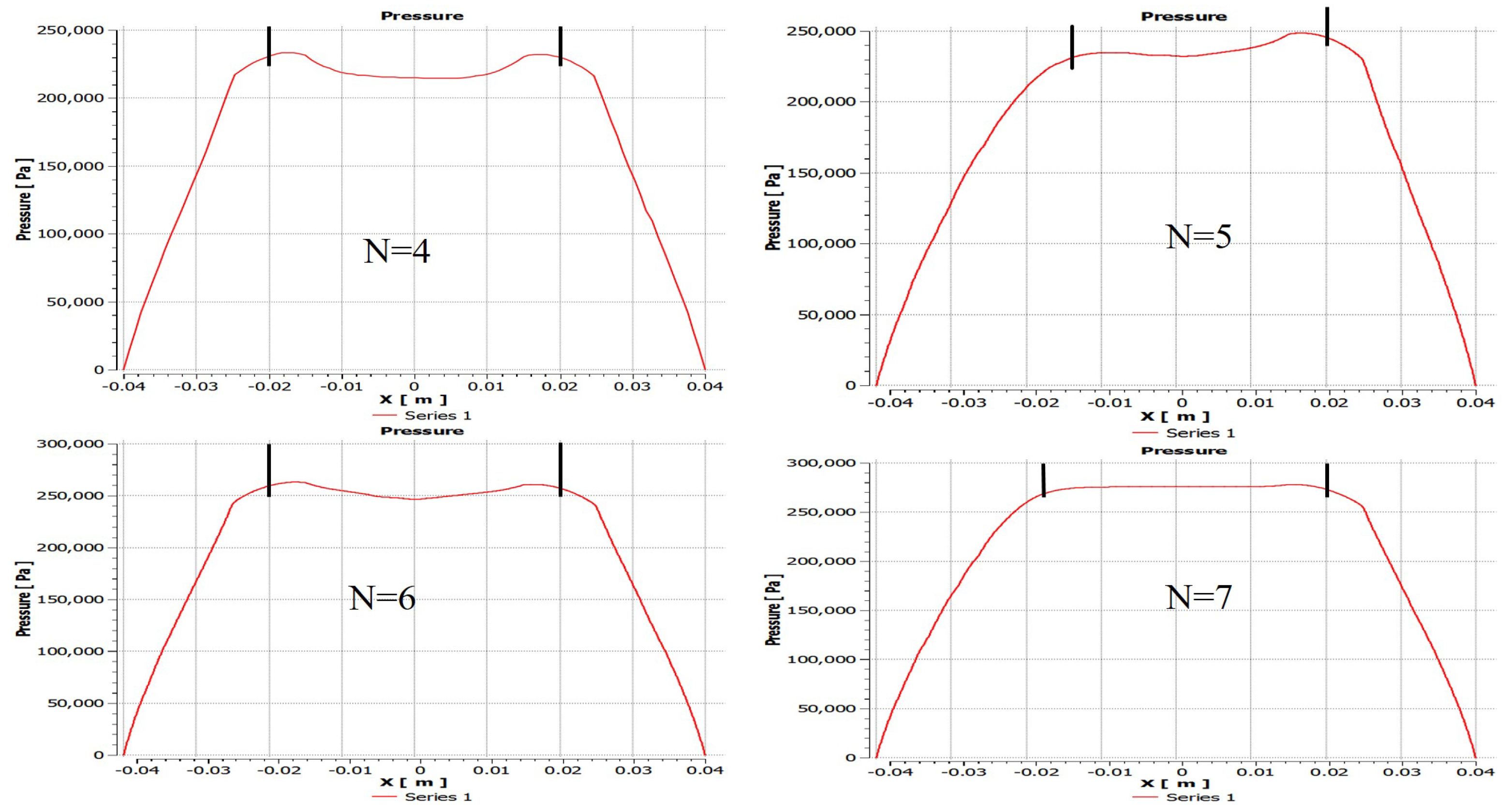
5.1. Influence of the Number of Partial Orifices (N = 4, 5, 6, 7)
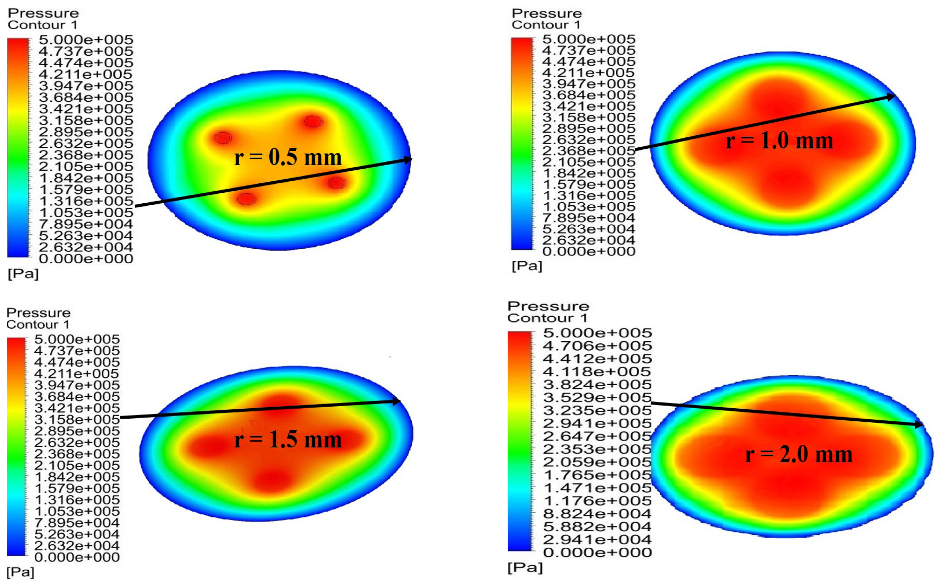
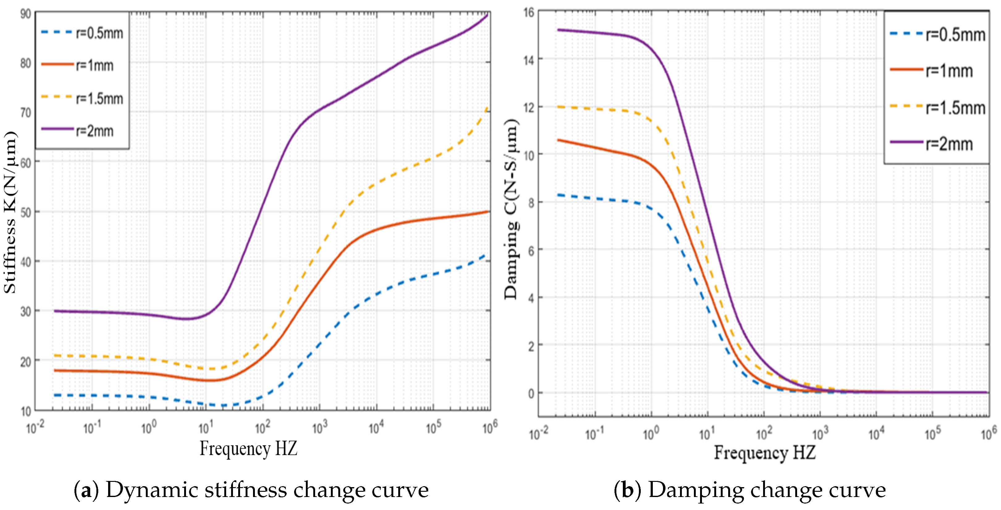
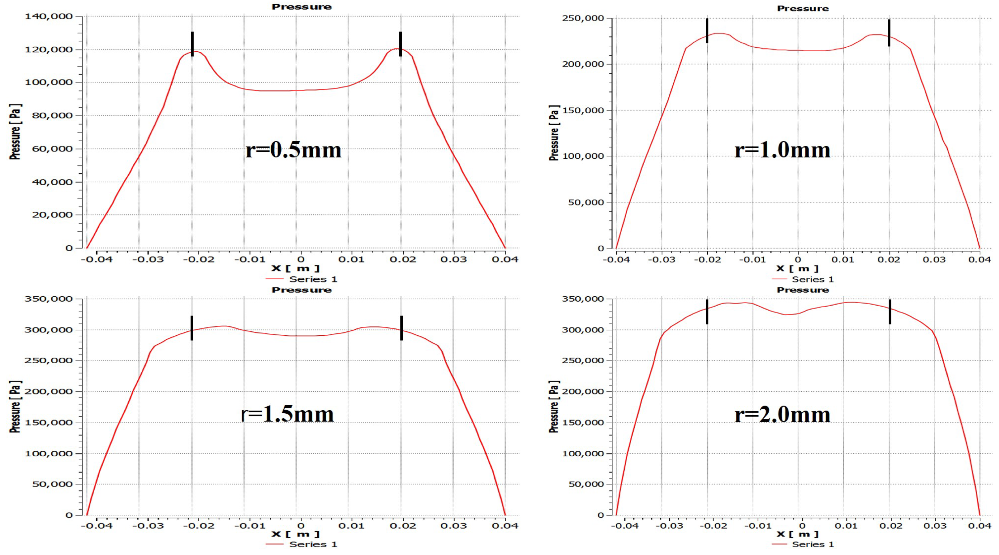
5.2. Influence of Radius of Partial Orifice (r = 0.5 mm, 15 mm, 1.5 mm, 2 mm)
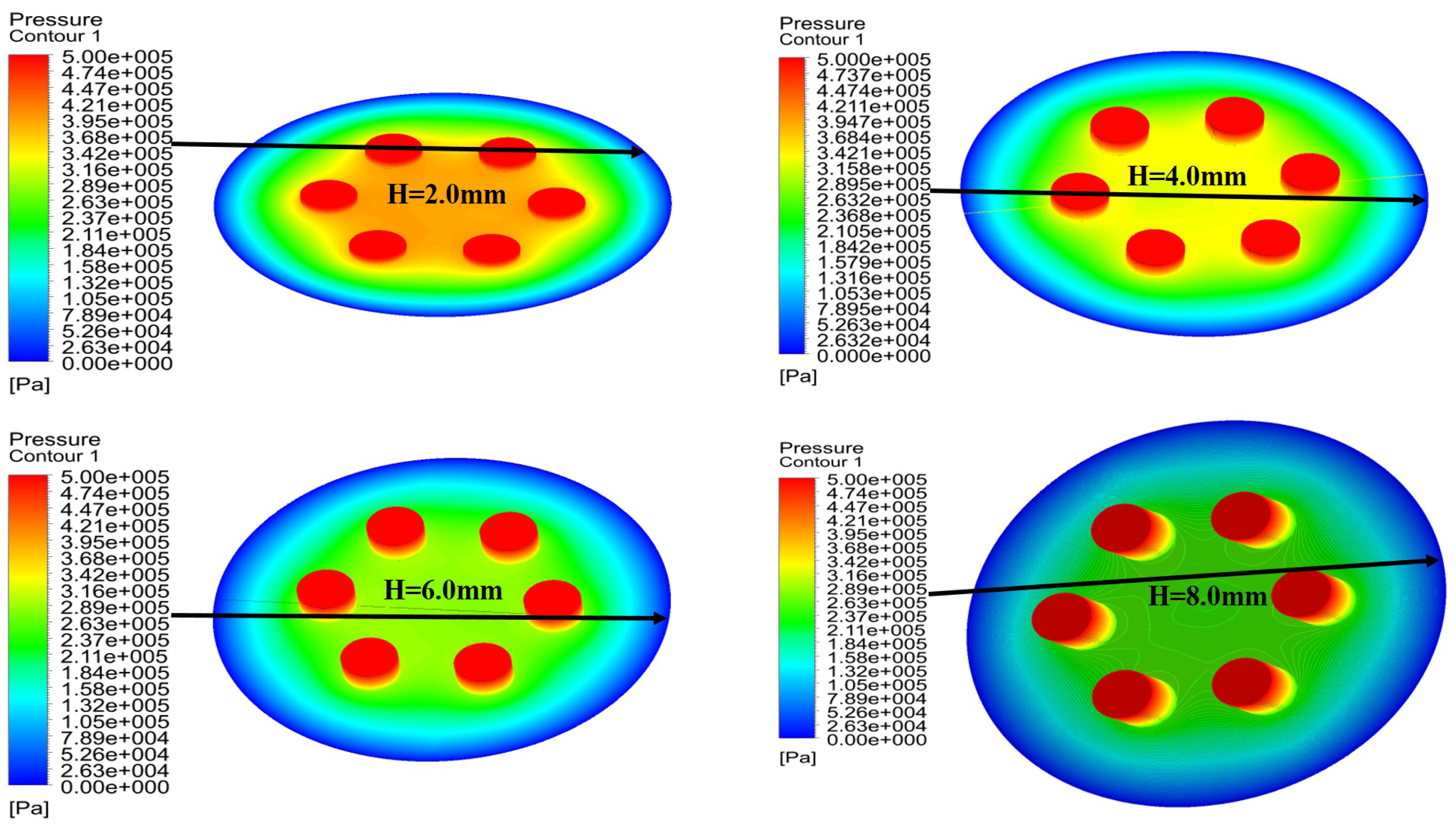
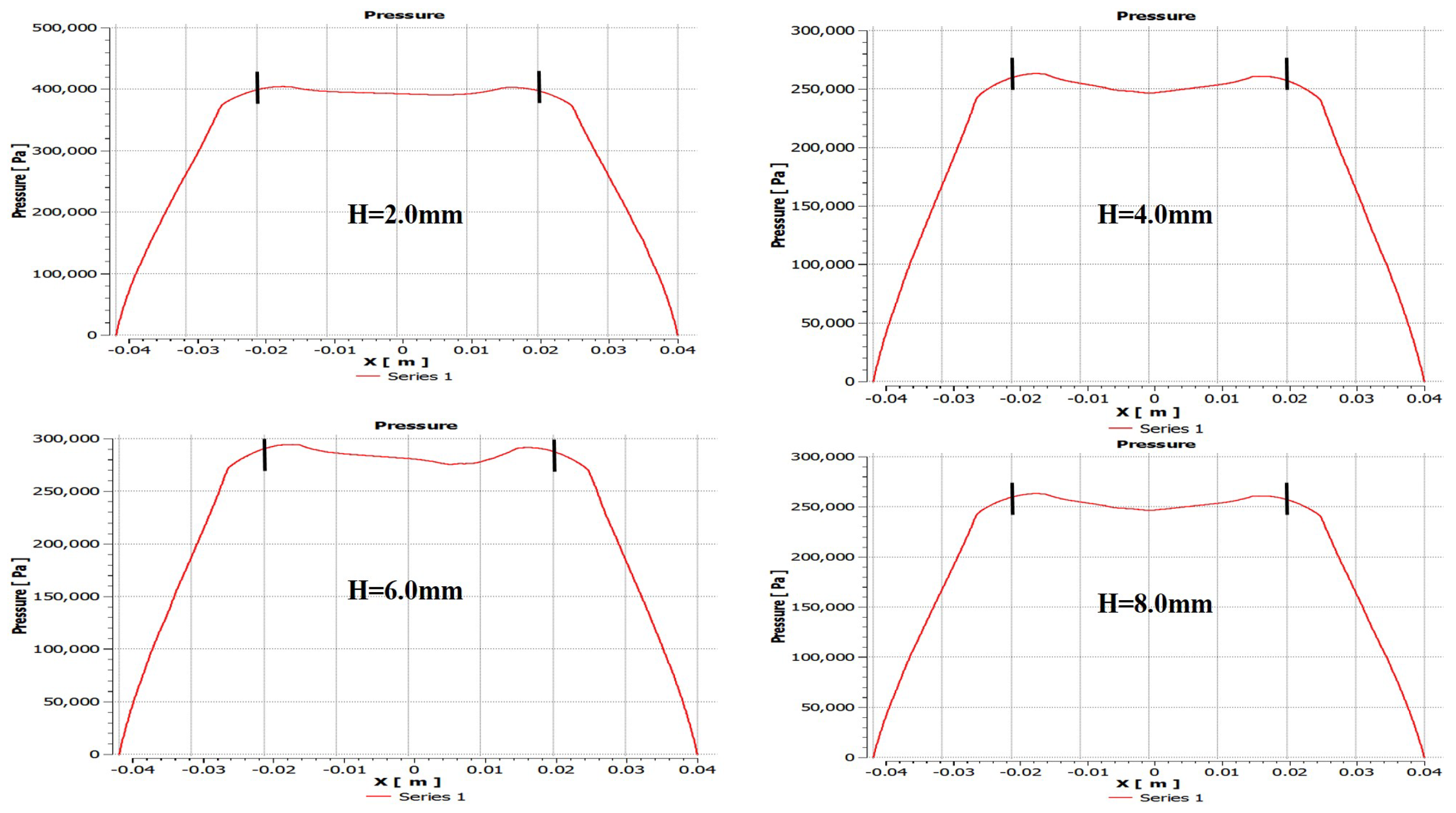
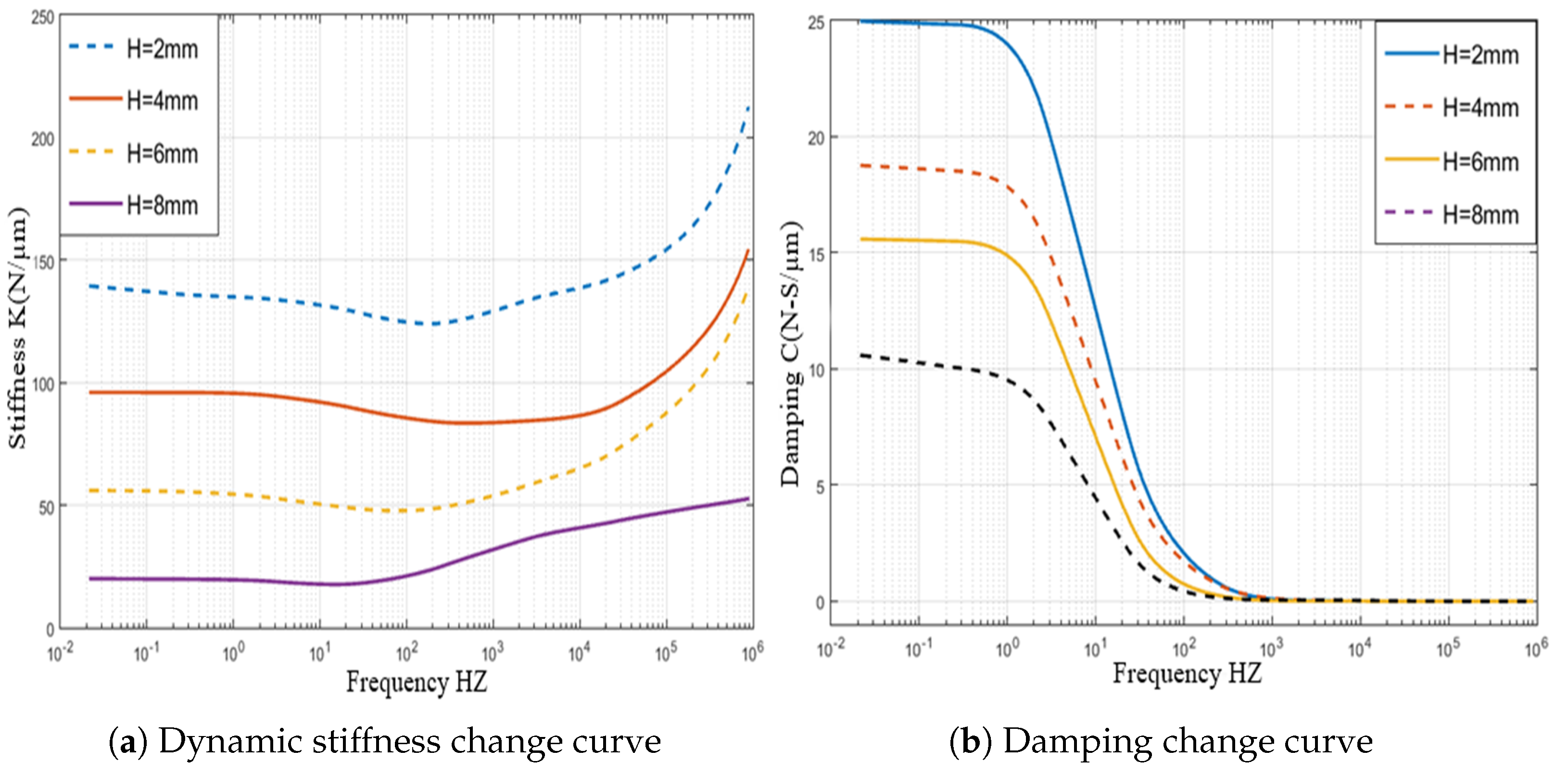
5.3. Influence of the Height of the Partial Porous Orifice (H = 2 mm, 4 mm, 6 mm, 8 mm)
6. Validation of Numerical Results through Experiments
7. Conclusions
Author Contributions
Funding
Conflicts of Interest
Nomenclature
| A | area of control volume boundary |
| viscous dissipation energy | |
| inertia permeability co-efficient | |
| S | source term |
| specific heat capacity | |
| scalar source term | |
| viscous permeability co-efficient | |
| gradT | temperature gradient |
| force in x-direction on body | |
| T | temperature |
| force in y-direction on body | |
| t | time |
| z-directional force on body | |
| u | velocity vector in x-direction |
| frequency | |
| v | velocity vector in y-direction |
| H | height of orifice |
| closed boundary control volume | |
| k | heat transfer co-efficient of fluid |
| w | velocity vector in z-direction |
| number of all boundary faces | |
| Cartesian coordinates | |
| N | orifice number |
| co-efficient of diffusion | |
| supply pressure | |
| porosity of porous material | |
| atmosphere pressure | |
| gas density | |
| r | radius of orifice |
| viscous stress of fluid |
References
- Chen, D.; Huo, C.; Cui, X.; Pan, R.; Fan, J.; An, C. Investigation the gas film in micro scale induced error on the performance of the aerostatic spindle in ultra-precision machining. Mech. Syst. Signal Process. 2018, 105, 488–501. [Google Scholar] [CrossRef]
- Zhang, S.; To, S.; Wang, H. A theoretical and experimental investigation into five-DOF dynamic characteristics of an aerostatic bearing spindle in ultra-precision diamond turning. Int. J. Mach. Tools Manuf. 2013, 71, 1–10. [Google Scholar] [CrossRef]
- Gao, Q.; Chen, W.; Lu, L.; Huo, D.; Cheng, K. Aerostatic bearings design and analysis with the application to precision engineering: State-of-the-art and future perspectives. Tribol. Int. 2019, 135, 1–17. [Google Scholar] [CrossRef]
- Schenk, C.; Buschmann, S.; Risse, S.; Eberhardt, R.; Tünnermann, A. Comparison between flat aerostatic gas-bearing pads with orifice and porous feedings at high-vacuum conditions. Precis. Eng. 2008, 32, 319–328. [Google Scholar] [CrossRef]
- Cui, H.; Wang, Y.; Yue, X.; Huang, M.; Wang, W. Effects of manufacturing errors on the static characteristics of aerostatic journal bearings with porous restrictor. Tribol. Int. 2017, 115, 246–260. [Google Scholar] [CrossRef]
- Chen, G.; Chen, Y. Multi-Field Coupling Dynamics Modeling of Aerostatic Spindle. Micromachines 2021, 12, 251. [Google Scholar] [CrossRef]
- KWAN, Y.P.; Corbett, J. Porous aerostatic bearings: An updated review. Wear 1998, 222, 69–73. [Google Scholar] [CrossRef]
- Plante, J.S.; Vogan, J.; El-Aguizy, T.; Slocum, A.H. A design model for circular porous air bearings using the 1D generalized flow method. Precis. Eng. 2005, 29, 336–346. [Google Scholar] [CrossRef]
- Boffey, D. A study of the stability of an externally-pressurized gas-lubricated thrust bearing with a flexible damped support. J. Lubr. Technol. 1978, 100, 364–368. [Google Scholar] [CrossRef]
- Boffey, D.; Desai, D. An experimental investigation into the rubber-stabilization of an externally-pressurized air-lubricated thrust bearing. J. Lubr. Technol. 1980, 102, 65–70. [Google Scholar] [CrossRef]
- Jia, C.; Pang, H.; Ma, W.; Qiu, M. Analysis of dynamic characteristics and stability prediction of gas bearings. Ind. Lubr. Tribol. 2017, 69, 123–130. [Google Scholar] [CrossRef]
- Blondeel, E.; Snoeys, R.; Devrieze, L. Dynamic stability of externally pressurized gas bearings. J. Lubr. Technol. 1980, 102, 511–519. [Google Scholar] [CrossRef]
- Suryawanshi, S.R.; Pattiwar, J.T. A Technical Review on Design & Thermal Behavior of Non-circular Hydrodynamic Journal Bearing using CFD Technique. Spvryan’S Int. J. Eng. Sci. Technol. (SEST) 2015, 2, 1–5. [Google Scholar]
- Sahto, M.P.; Wang, W.; Imran, M.; He, L.; Li, H.; Weiwei, G. Modelling and Simulation of Aerostatic Thrust Bearings. IEEE Access 2020, 8, 121299–121310. [Google Scholar] [CrossRef]
- Constantinescu, V.; Galetuse, S. On the dynamic stability of the spiral-grooved gas-lubricated thrust bearing. J. Tribol. 1987, 109, 183188. [Google Scholar] [CrossRef]
- Jolly, P.; Hassini, M.A.; Arghir, M.; Bonneau, O. Identification of stiffness and damping coefficients of hydrostatic bearing with angled injection. Proc. Inst. Mech. Eng. Part J J. Eng. Tribol. 2013, 227, 905–911. [Google Scholar] [CrossRef]
- Plessers, P.; Snoeys, R. Dynamic stability of mechanical structures containing externally pressurized gas-lubricated thrust bearings. J. Tribol. 1988, 110, 271–278. [Google Scholar] [CrossRef]
- Yoshimoto, S.; Kohno, K. Static and dynamic characteristics of aerostatic circular porous thrust bearings (effect of the shape of the air supply area). J. Tribol. 2001, 123, 501–508. [Google Scholar] [CrossRef]
- Cui, H.; Wang, Y.; Yue, X.; Huang, M.; Wang, W.; Jiang, Z. Numerical analysis and experimental investigation into the effects of manufacturing errors on the running accuracy of the aerostatic porous spindle. Tribol. Int. 2018, 118, 20–36. [Google Scholar] [CrossRef]
- Zhang, J.; Zou, D.; Ta, N.; Rao, Z. Numerical research of pressure depression in aerostatic thrust bearing with inherent orifice. Tribol. Int. 2018, 123, 385–396. [Google Scholar] [CrossRef]
- Peixoto, T.F.; Daniel, G.B.; Cavalca, K.L. Experimental Estimation of Equivalent Damping Coefficient of Thrust Bearings. In Proceedings of the International Symposium on Dynamic Problems of Mechanics, São Sebastião, Brazil, 5–10 March 2017; pp. 17–29. [Google Scholar]
- Wang, W.; Cheng, X.; Zhang, M.; Gong, W.; Cui, H. Effect of the deformation of porous materials on the performance of aerostatic bearings by fluid-solid interaction method. Tribol. Int. 2020, 150, 106391. [Google Scholar] [CrossRef]
- Gao, Q.; Lu, L.; Chen, W.; Chen, G.; Wang, G. A novel modeling method to investigate the performance of aerostatic spindle considering the fluid-structure interaction. Tribol. Int. 2017, 115, 461–469. [Google Scholar] [CrossRef]
- Zhuang, H.; Ding, J.; Chen, P.; Chang, Y.; Zeng, X.; Yang, H.; Liu, X.; Wei, W. Numerical Study on Static and Dynamic Performances of a Double-Pad Annular Inherently Compensated Aerostatic Thrust Bearing. J. Tribol. 2019, 141, 051701. [Google Scholar] [CrossRef]
- Zhao, X.L.; Dong, H.; Fang, Z.; Chen, D.D.; Zhang, J.A. Study on dynamic characteristics of aerostatic bearing with elastic equalizing pressure groove. Shock Vib. 2018, 2018, 6142386. [Google Scholar] [CrossRef] [Green Version]
- Fourka, M.; Bonis, M. Comparison between externally pressurized gas thrust bearings with different orifice and porous feeding systems. Wear 1997, 210, 311–317. [Google Scholar] [CrossRef]
- Hongxia, Z.; Yuntang, L.; Yingxiao, L.; Dandan, L. CFD Investigation on the Performance of Aerostatic Thrust Bearing with Exhaust Slots Used in Low-vacuum Condition. In Proceedings of the 1st International Conference on Mechanical Engineering and Material Science, Shanghai, China, 28–30 December 2012. [Google Scholar]
- Dong, H.; Zhao, X.L.; Zhang, J.a. Static characteristic analysis and experimental research of aerostatic thrust bearing with annular elastic uniform pressure plate. Adv. Mech. Eng. 2015, 7, 1687814015575454. [Google Scholar] [CrossRef] [Green Version]
- Kodnyanko, V.; Shatokhin, S.; Kurzakov, A.; Pikalov, Y.; Pikalov, I.; Grigorieva, O.; Strok, L.; Brungardt, M. Numerical Modeling on the Compliance and Load Capacity of a Two-Row Aerostatic Journal Bearing with Longitudinal Microgrooves in the Inter-Row Zone. Appl. Sci. 2021, 11, 5714. [Google Scholar] [CrossRef]
- Cui, H.; Wang, Y.; Yang, H.; Zhou, L.; Li, H.; Wang, W.; Zhao, C. Numerical analysis and experimental research on the angular stiffness of aerostatic bearings. Tribol. Int. 2018, 120, 166–178. [Google Scholar] [CrossRef]


| Design Variable | Orifice & Porous |
|---|---|
| Outlet pressure | 0 bar |
| Inlet pressure | 5 bar |
| Operating pressure | 101,325 Pa |
| Temperature | 293 K |
| Dynamic viscosity | Ns/(m) |
| Gas density | |
| Film thickness | 5–15 m |
| Bearing outer diameter | 80,000 m |
| Bearing inner diameter | 48,000 m |
| Orifices height | 2 mm/4 mm/6 mm/8 mm |
| Orifices radius | 0.5 mm/1 mm/1.5 mm/2 mm |
| Viscous resistance coefficient | |
| Porosity | 0.3 |
| Object Name | Geometry |
|---|---|
| State | Fully Defined |
| Bounding box | |
| Length X | 80 mm |
| Length Y | 80 mm |
| Length Z | 8 mm |
| Properties | |
| Volume | |
| Scale Factor Value | 1 |
| Statistics | |
| Bodies | 9 |
| Active Bodies | 9 |
| Nodes | 312,839 |
| Elements | 283,525 |
| Mesh Metric | None |
Publisher’s Note: MDPI stays neutral with regard to jurisdictional claims in published maps and institutional affiliations. |
© 2021 by the authors. Licensee MDPI, Basel, Switzerland. This article is an open access article distributed under the terms and conditions of the Creative Commons Attribution (CC BY) license (https://creativecommons.org/licenses/by/4.0/).
Share and Cite
Sahto, M.P.; Wang, W.; Sanjrani, A.N.; Hao, C.; Shah, S.A. Dynamic Performance of Partially Orifice Porous Aerostatic Thrust Bearing. Micromachines 2021, 12, 989. https://doi.org/10.3390/mi12080989
Sahto MP, Wang W, Sanjrani AN, Hao C, Shah SA. Dynamic Performance of Partially Orifice Porous Aerostatic Thrust Bearing. Micromachines. 2021; 12(8):989. https://doi.org/10.3390/mi12080989
Chicago/Turabian StyleSahto, Muhammad Punhal, Wei Wang, Ali Nawaz Sanjrani, Chengxu Hao, and Sadiq Ali Shah. 2021. "Dynamic Performance of Partially Orifice Porous Aerostatic Thrust Bearing" Micromachines 12, no. 8: 989. https://doi.org/10.3390/mi12080989
APA StyleSahto, M. P., Wang, W., Sanjrani, A. N., Hao, C., & Shah, S. A. (2021). Dynamic Performance of Partially Orifice Porous Aerostatic Thrust Bearing. Micromachines, 12(8), 989. https://doi.org/10.3390/mi12080989