
Analysis of Wire-Cut Electro Discharge Machining of Polymer Composite Materials


Abstract
1. Introduction
Purpose of Study
- To assess the influence of key process parameters on the cut width (kerf) and surface quality of PCM sandwiched in Titanium alloy.
- To develop a regression model using response surface methodology, which is further examined with the experimental results for non-linear machining cut-width on the selected PCM.
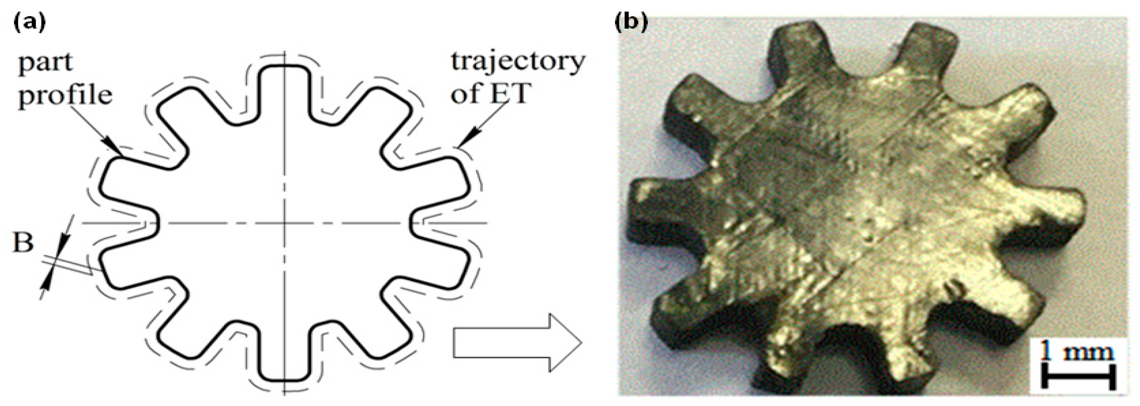
- To determine the trajectory of ET to machine PCM in the form of a complex shaped part, such as a gear.
2. Material and Methods
2.1. Material
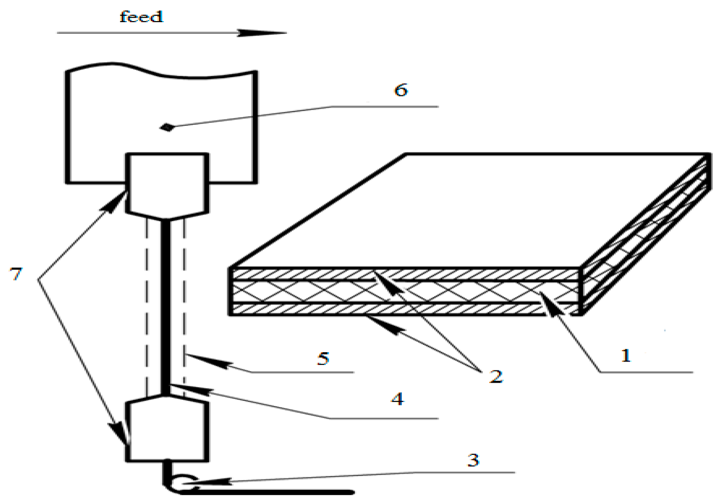
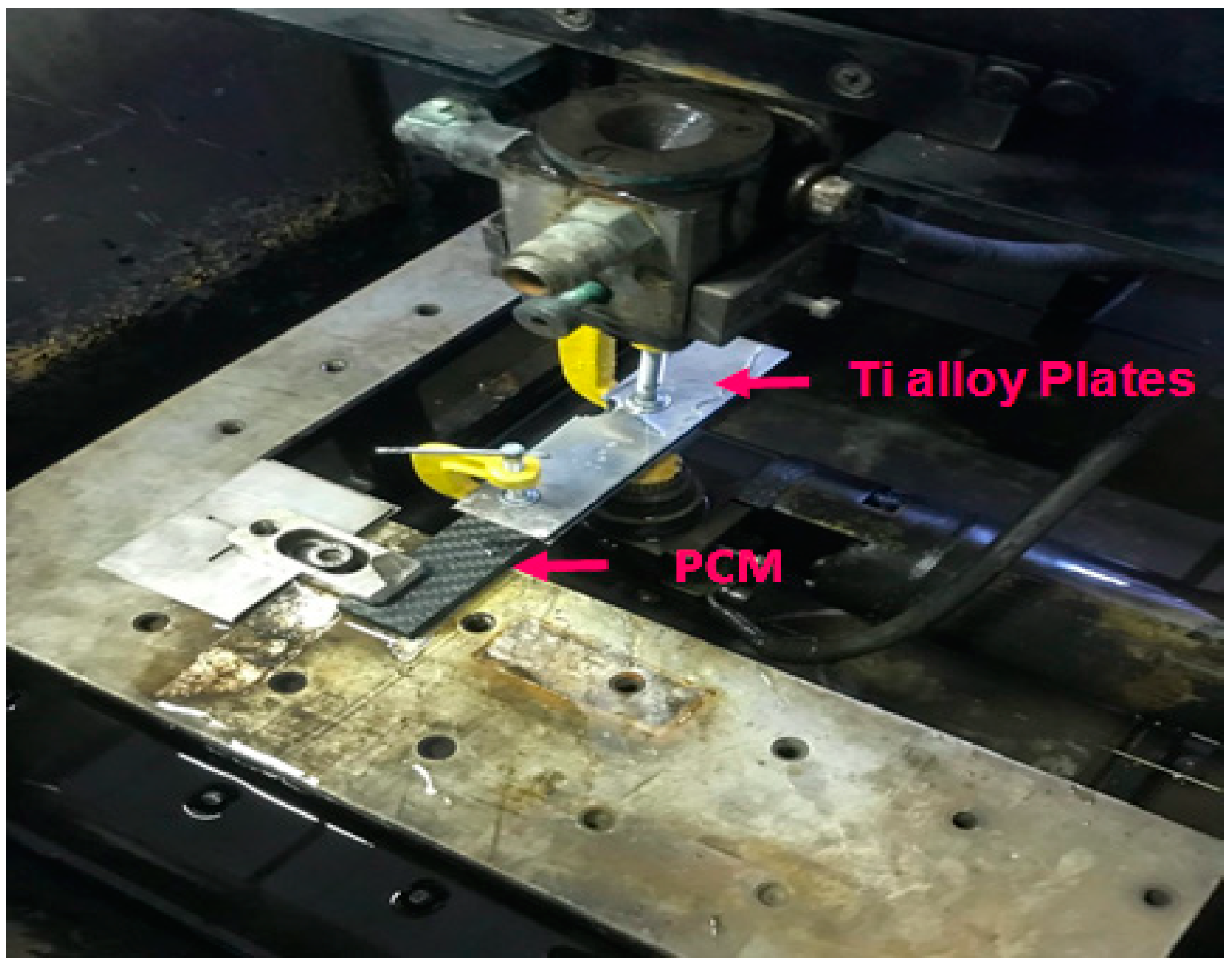
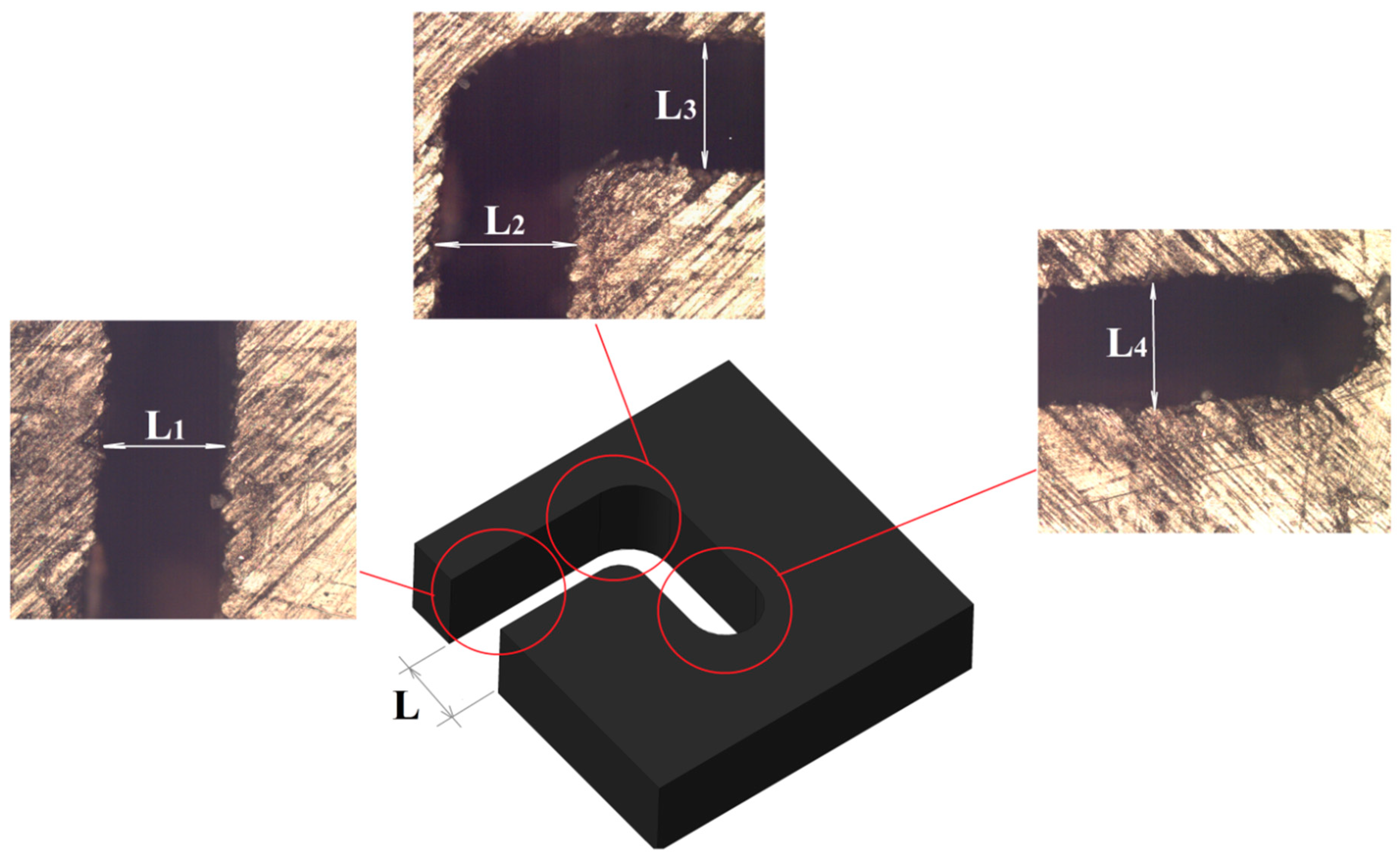
2.2. Method
3. Results and Discussion
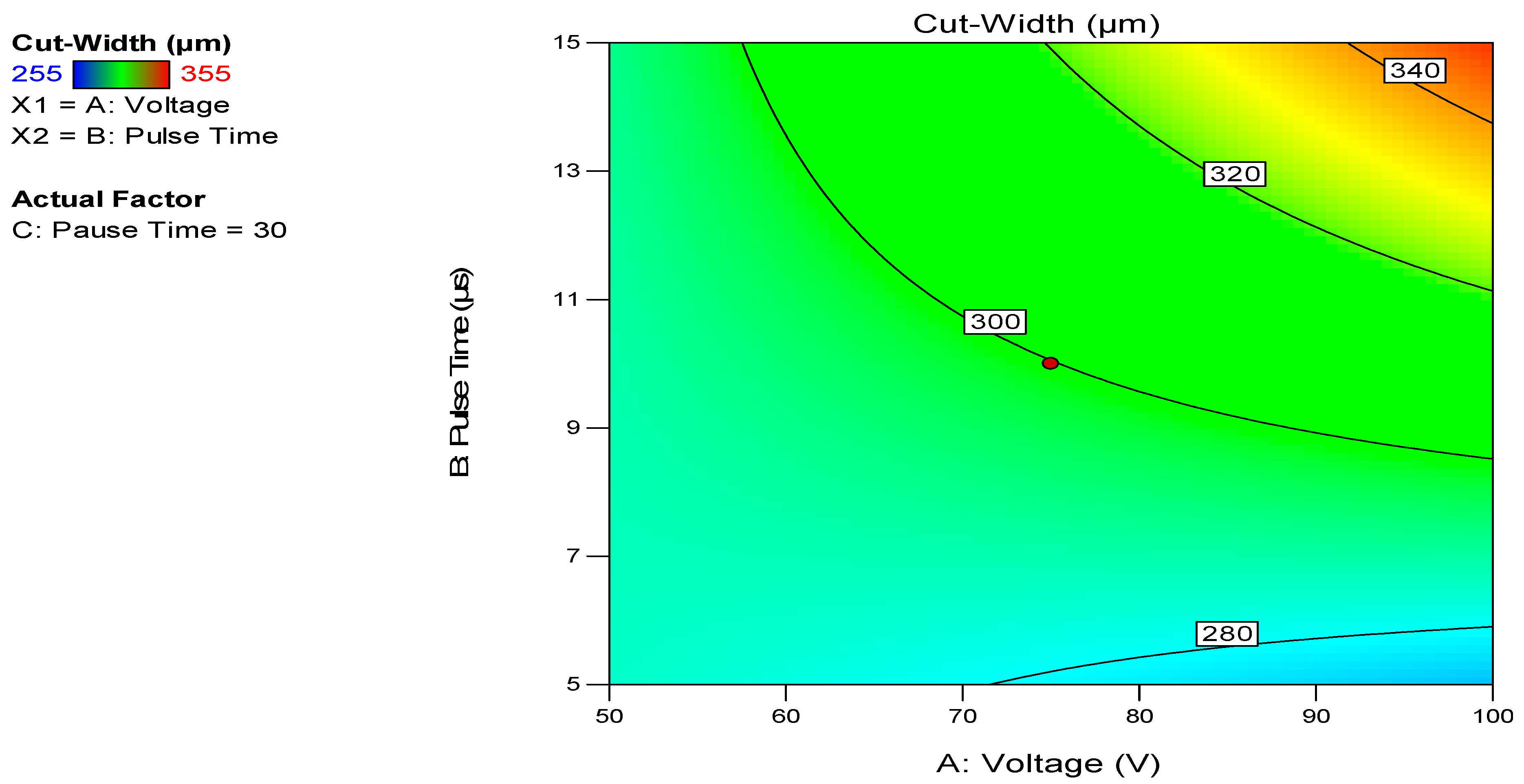
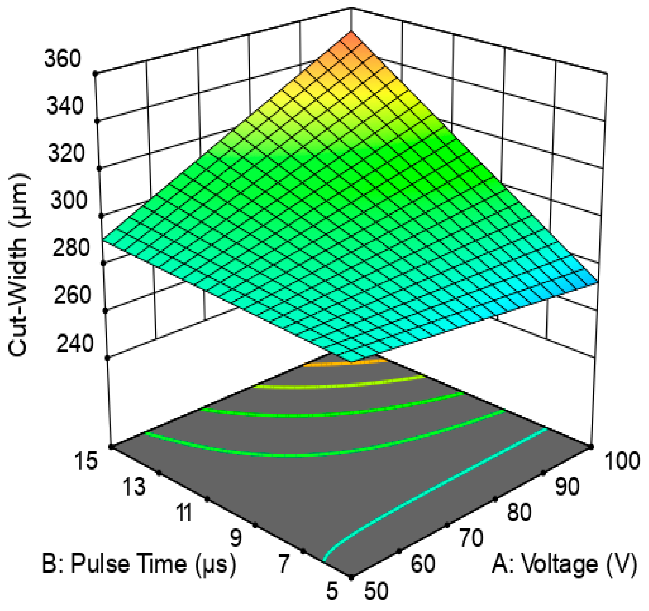
Examination of the Predicted Model forWIRE-EDM onComplex-Shaped PCM Parts
4. Conclusions
Author Contributions
Funding
Conflicts of Interest
References
- Sarde, B.; Patil, Y.D. Recent Research Status on Polymer Composite Used in Concrete—An Overview. Mater. Today Proc. 2019, 18, 3780–3790. [Google Scholar] [CrossRef]
- Yahaya, R.; Sapuan, S.; Jawaid, M.; Leman, Z.; Zainudin, E. Mechanical performance of woven kenaf-Kevlar hybrid composites. J. Reinf. Plast. Compos. 2014, 33, 2242–2254. [Google Scholar] [CrossRef]
- Hsissou, R.; Benhiba, F.; Echihi, S.; Benkhaya, S.; Hilali, M.; Berisha, A.; Briche, S.; Zarrouk, A.; Nouneh, K.; Elharfi, A. New epoxy composite polymers as a potential anticorrosive coatings for carbon steel in 3.5% NaCl solution: Experimental and computational approaches. Chem. Data Collect. 2021, 31, 100619. [Google Scholar] [CrossRef]
- Valino, A.D.; Dizon, J.R.C.; Espera, A.H.; Chen, Q.; Messman, J.; Advincula, R.C. Advances in 3D printing of thermoplastic polymer composites and nanocomposites. Prog. Polym. Sci. 2019, 98, 101162. [Google Scholar] [CrossRef]
- Hsissou, R.; Bekhta, A.; Dagdag, O.; El Bachiri, A.; Rafik, M.; Elharfi, A. Rheological properties of composite polymers and hybrid nanocomposites. Heliyon 2020, 6, e04187. [Google Scholar] [CrossRef]
- Mehra, N.; Mu, L.; Ji, T.; Yang, X.; Kong, J.; Gu, J.; Zhu, J. Thermal transport in polymeric materials and across composite interfaces. Appl. Mater. Today 2018, 12, 92–130. [Google Scholar] [CrossRef]
- Thomason, J. A review of the analysis and characterisation of polymeric glass fibre sizings. Polym. Test. 2020, 85, 106421. [Google Scholar] [CrossRef]
- Shlykov, E.S.; Ablyaz, T.R.; Oglezneva, S.A. Electrical Discharge Machining of Polymer Composites. Russ. Eng. Res. 2020, 40, 878–879. [Google Scholar] [CrossRef]
- Ablyaz, T.R.; Muratov, K.R.; Shlykov, E.S.; Shipunov, G.S.; Shakirzyanov, T.V. Electric-Discharge Machining of Polymer Composites. Russ. Eng. Res. 2019, 39, 898–900. [Google Scholar] [CrossRef]
- Yao, Y.; Wang, B.; Wang, J.; Jin, H.; Zhang, Y.; Dong, S. Chemical machining of Zerodur material with atmospheric pressure plasma jet. CIRP Ann. 2010, 59, 337–340. [Google Scholar] [CrossRef]
- Shimpi, J.R.; Sidhaye, D.S.; Prasad, B.L. Digestive Ripening: A Fine Chemical Machining Process on the Nanoscale. Langmuir 2017, 33, 9491–9507. [Google Scholar] [CrossRef] [PubMed]
- Romoli, L.; Tantussi, G.; Dini, G. Experimental approach to the laser machining of PMMA substrates for the fabrication of microfluidic devices. Opt. Lasers Eng. 2011, 49, 419–427. [Google Scholar] [CrossRef]
- Li, Z.; Zheng, H.; Lim, G.; Chu, P.; Li, L. Study on UV laser machining quality of carbon fibre reinforced composites. Compos. Part A Appl. Sci. Manuf. 2010, 41, 1403–1408. [Google Scholar] [CrossRef]
- Samant, A.N.; Dahotre, N.B. Laser machining of structural ceramics—A review. J. Eur. Ceram. Soc. 2009, 29, 969–993. [Google Scholar] [CrossRef]
- Pham, D.T.; Dimov, S.S.; Ji, C.; Petkov, P.V.; Dobrev, T. Laser milling as a ‘rapid’ micromanufacturing process. Proc. Inst. Mech. Eng. Part B J. Eng. Manuf. 2004, 218, 1–7. [Google Scholar] [CrossRef]
- Shi, B.; Dai, Y.; Xie, X.; Li, S.; Zhou, L. Arc-Enhanced Plasma Machining Technology for High Efficiency Machining of Silicon Carbide. Plasma Chem. Plasma Process. 2016, 36, 891–900. [Google Scholar] [CrossRef]
- Malhotra, R.; Saxena, I.; Ehmann, K.F.; Cao, J. Laser-induced plasma micro-machining (LIPMM) for enhanced productivity and flexibility in laser-based micro-machining processes. CIRP Ann. 2013, 62, 211–214. [Google Scholar] [CrossRef]
- Spinney, P.S.; Howitt, D.G.; Smith, R.L.; Collins, S.D. Nanopore formation by low-energy focused electron beam machining. Nanotechnology 2010, 21, 375301. [Google Scholar] [CrossRef]
- Parthasarathy, J.; Starly, B.; Raman, S.; Christensen, A. Mechanical evaluation of porous titanium (Ti6Al4V) structures with electron beam melting (EBM). J. Mech. Behav. Biomed. Mater. 2010, 3, 249–259. [Google Scholar] [CrossRef]
- Koike, M.; Martinez, K.; Guo, L.; Chahine, G.; Kovacevic, R.; Okabe, T. Evaluation of titanium alloy fabricated using electron beam melting system for dental applications. J. Mater. Process. Technol. 2011, 211, 1400–1408. [Google Scholar] [CrossRef]
- Rajurkar, K.; Sundaram, M.; Malshe, A. Review of Electrochemical and Electrodischarge Machining. Procedia CIRP 2013, 6, 13–26. [Google Scholar] [CrossRef]
- Tiwari, A.; Mandal, A.; Kumar, K. Multi-objective Optimization of Electro-chemical Machining by Non-dominated Sorting Genetic Algorithm. Mater. Today Proc. 2015, 2, 2569–2575. [Google Scholar] [CrossRef]
- Alberdi, A.; Rivero, A.; de Lacalle, L.N.L.; Etxeberria, I.; Suárez, A. Effect of process parameter on the kerf geometry in abrasive water jet milling. Int. J. Adv. Manuf. Technol. 2010, 51, 467–480. [Google Scholar] [CrossRef]
- Ting, H.; Abou-El-Hossein, K.; Chua, H. Review of micromachining of ceramics by etching. Trans. Nonferrous Met. Soc. China 2009, 19, S1–S16. [Google Scholar] [CrossRef]
- Matsumura, T.; Muramatsu, T.; Fueki, S. Abrasive water jet machining of glass with stagnation effect. CIRP Ann. 2011, 60, 355–358. [Google Scholar] [CrossRef]
- Gupta, V.; Pandey, P.; Garg, M.P.; Khanna, R.; Batra, N. Minimization of Kerf Taper Angle and Kerf Width Using Taguchi’s Method in Abrasive Water Jet Machining of Marble. Procedia Mater. Sci. 2014, 6, 140–149. [Google Scholar] [CrossRef]
- Deris, A.M.; Zain, A.M.; Sallehuddin, R. A note of hybrid GR-SVM for prediction of surface roughness in abrasive water jet machining: A response. Meccanica 2017, 52, 1993–1994. [Google Scholar] [CrossRef]
- Panner Selvam, M.; Ranjith Kumar, P. Optimization Kerf Width and Surface Roughness in Wirecut Electrical Discharge Machining Using Brass Wire. Mech. Mech. Eng. 2017, 21, 37–55. [Google Scholar]
- Maher, I.; Ling, L.H.; Sarhan, A.A.D.; Hamdi, M. Improve wire EDM performance at different machining parameters—ANFIS modeling. IFAC-PapersOnLine 2015, 48, 105–110. [Google Scholar] [CrossRef]
- Wu, C.; Cao, S.; Zhao, Y.J.; Qi, H.; Liu, X.; Liu, G.; Guo, J.; Li, H.N. Preheating assisted wire EDM of semi-conductive CFRPs: Principle and anisotropy. J. Mater. Process. Technol. 2021, 288, 116915. [Google Scholar] [CrossRef]
- Abbas, N.M.; Solomon, D.G.; Bahari, F. A review on current research trends in electrical discharge machining (EDM). Int. J. Mach. Tools Manuf. 2007, 47, 1214–1228. [Google Scholar] [CrossRef]
- Abdallah, R.; Soo, S.L.; Hood, R. A feasibility study on wire electrical discharge machining of carbon fibre reinforced plastic composites. Procedia CIRP 2018, 77, 195–198. [Google Scholar] [CrossRef]
- Dutta, H.; Debnath, K.; Sarma, D.K. Investigation on cutting of thin carbon fiber-reinforced polymer composite plate using sandwich electrode-assisted wire electrical-discharge machining. Proc. Inst. Mech. Eng. Part E J. Process. Mech. Eng. 2021. [Google Scholar] [CrossRef]
- Fukuzawa, Y.; Katougi, H.; Mohri, N.; Furutani, K.; Tani, T. Machining properties of ceramics with an electric discharge machine. In Proceedings of the XII ISEM, Aachen, Germany, 11–13 May 1998; pp. 445–454. [Google Scholar]
- Mohri, N.; Fukuzawa, Y.; Tani, T.; Saito, N.; Furutani, K. Assisting Electrode Method for Machining Insulating Ceramics. CIRP Ann. 1996, 45, 201–204. [Google Scholar] [CrossRef]
- Mohri, N.; Fukusima, Y.; Fukuzawa, Y.; Tani, T.; Saito, N. Layer Generation Process on Work-piece in Electrical Discharge Machining. CIRP Ann. 2003, 52, 157–160. [Google Scholar] [CrossRef]
- Lauwers, B.; Kruth, J.; Liu, W.; Eeraerts, W.; Schacht, B.; Bleys, P. Investigation of material removal mechanisms in EDM of composite ceramic materials. J. Mater. Process. Technol. 2004, 149, 347–352. [Google Scholar] [CrossRef]
- Puertas, I.; Luis, C. A study on the electrical discharge machining of conductive ceramics. J. Mater. Process. Technol. 2004, 153–154, 1033–1038. [Google Scholar] [CrossRef]
- Kucukturk, G.; Cogun, C. A New Method for Machining of Electrically Nonconductive Workpieces Using Electric Discharge Machining Technique. Mach. Sci. Technol. 2010, 14, 189–207. [Google Scholar] [CrossRef]
- Hösel, T.; Müller, C.; Reinecke, H. Spark erosive structuring of electrically nonconductive zirconia with an assisting electrode. CIRP J. Manuf. Sci. Technol. 2011, 4, 357–361. [Google Scholar] [CrossRef]
- Wüthrich, R.; Fascio, V. Machining of non-conducting materials using electrochemical discharge phenomenon—An overview. Int. J. Mach. Tools Manuf. 2005, 45, 1095–1108. [Google Scholar] [CrossRef]
- Schubert, A.; Zeidler, H.; Wolf, N.; Hackert, M. Micro Electro Discharge Machining of Electrically Nonconductive Ceramics. In Proceedings of the 14th International Esaform Conference on Material Forming: ESAFORM 2011, Belfast, UK, 27–29 April 2011; AIP Publishing: College Park, MD, USA, 2011; pp. 1303–1308. [Google Scholar]
- Saleh, M.; Anwar, S.; El-Tamimi, A.; Mohammed, M.K.; Ahmad, S. Milling Microchannels in Monel 400 Alloy by Wire EDM: An Experimental Analysis. Micromachines 2020, 11, 469. [Google Scholar] [CrossRef] [PubMed]
- Kumar, V.; Kumar, V.; Jangra, K.K. An experimental analysis and optimization of machining rate and surface characteristics in WEDM of Monel-400 using RSM and desirability approach. J. Ind. Eng. Int. 2015, 11, 297–307. [Google Scholar] [CrossRef]
- Manjaiah, M.; Narendranath, S.; Basavarajappa, S. Wire Electro Discharge Machining Performance of TiNiCu Shape Memory Alloy. Silicon 2016, 8, 467–475. [Google Scholar] [CrossRef]
- Ahmed, N.; Mughal, M.P.; Shoaib, W.; Raza, S.F.; Alahmari, A.M. WEDM of Copper for the Fabrication of Large Surface-Area Micro-Channels: A Prerequisite for the High Heat-Transfer Rate. Micromachines 2020, 11, 173. [Google Scholar] [CrossRef] [PubMed]
- Korlos, A.; Tzetzis, D.; Mansour, G.; Sargis, D.; David, C. The delamination effect of drilling and electro-discharge machining on the tensile strength of woven composites as studied by X-ray computed tomography. Int. J. Mach. Mach. Mater. (IJMMM) 2016, 18, 426–448. [Google Scholar] [CrossRef]
- Wang, R.; Wang, J.; Yuan, W. Analysis and Optimization of a Microchannel Heat Sink with V-Ribs Using Nanofluids for Micro Solar Cells. Micromachines 2019, 10, 620. [Google Scholar] [CrossRef]
- Yamada, H.; Mohri, N.; Furutani, K.; Saito, N.; Magara, T. Transient Response of Wire Vibration System in Wire Electrical Discharge Machining. J. Jpn. Soc. Precis. Eng. 1997, 63, 1548–1552. [Google Scholar] [CrossRef]
- Enache, S.; Opran, C. Dynamic Stability of the Technological Machining System in EDM. Ann. CIRP 1993, 42, 209–214. [Google Scholar] [CrossRef]
- Yan, M.-T.; Lai, Y.-P. Surface quality improvement of wire-EDM using a fine-finish power supply. Int. J. Mach. Tools Manuf. 2007, 47, 1686–1694. [Google Scholar] [CrossRef]
- Schneider, A.; Hommel, G.; Blettner, M. Linear Regression Analysis: Part 14 of a Series on Evaluation of Scientific Publications. Dtsch. Aerzteblatt Online 2010, 107, 776–782. [Google Scholar] [CrossRef]


| Property | Average Value |
|---|---|
| Filler material | Carbon fabrics twill (Porcher-3692) |
| Heat resistance °C | 170° |
| Monolayer thickness, mm | 0.2 |
| Tensile strength, MPA | 945 |
| Tensile modulus, GPA | 69 |
| Compressive strength, MPA | 610 |
| Compression modulus, GPA | 54 |
| Density of carbon fiber reinforced polymer (CFRP), kg/m3 | 1550 |
| Weaving type | Twill, at an angle of 90° |
| Electrical conductivity, S/m | 10−7 |
| Factors, Units | Units | Lower Level(−1) | Upper Level(+1) | Average Level | Lower “Star” Point | Top “Star” Point |
|---|---|---|---|---|---|---|
| U | V | 50 | 100 | 75 | 40 | 110 |
| Ton | µs | 5 | 15 | 10 | 2 | 20 |
| Toff | µs | 10 | 50 | 30 | 5 | 60 |
| Exp. No. | Process Parameters | Response | ||
|---|---|---|---|---|
| Voltage U (V) | Pulse Duration Ton (µs) | Pause Time Toff (µs) | Cut-Width
L (µm) | |
| 1 | 100 | 15 | 50 | 337 |
| 2 | 50 | 15 | 10 | 286 |
| 3 | 100 | 5 | 50 | 280 |
| 4 | 75 | 10 | 60 | 323 |
| 5 | 75 | 10 | 5 | 327 |
| 6 | 50 | 5 | 10 | 275 |
| 7 | 50 | 5 | 50 | 284 |
| 8 | 75 | 20 | 30 | 355 |
| 9 | 100 | 15 | 10 | 342 |
| 10 | 50 | 15 | 50 | 276 |
| 11 | 75 | 2 | 30 | 273 |
| 12 | 110 | 10 | 30 | 315 |
| 13 | 75 | 10 | 30 | 294 |
| 14 | 100 | 5 | 10 | 255 |
| 15 | 40 | 10 | 30 | 283 |
| Model | p-Value | Adjusted R2 | Predicted R2 | |
|---|---|---|---|---|
| Linear | 0.0127 | 0.5061 | 0.2412 | - |
| 2-way interaction | 0.0663 | 0.7100 | 0.3711 | Suggested Model |
| Quadratic | 0.4820 | 0.7049 | −0.0121 | - |
| ANOVA for Response Surface | ||||||
|---|---|---|---|---|---|---|
| Source | Sum of Squares | df | Mean Square | F-Value | p-Value | |
| Model | 10,655.21 | 6 | 1775.87 | 6.71 | 0.0085 | Significant |
| U-Voltage | 1593.02 | 1 | 1593.02 | 6.02 | 0.0397 | - |
| Ton | 6189.06 | 1 | 6189.06 | 23.40 | 0.0013 | - |
| Toff | 33.21 | 1 | 33.21 | 0.1256 | 0.7322 | - |
| U × Ton | 2485.13 | 1 | 2485.13 | 9.40 | 0.0155 | - |
| U × Toff | 55.13 | 1 | 55.13 | 0.2084 | 0.6602 | - |
| Ton × Ton | 300.12 | 1 | 300.12 | 1.13 | 0.3179 | - |
| Residual | 2116.12 | 8 | 264.52 | - | - | - |
| Total | 12,771.33 | 14 | 1775.87 | - | - | - |
| ANOVA for Response Surface | ||||||
|---|---|---|---|---|---|---|
| Source | Sum of Squares | df | Mean Square | F-Value | p-Value | |
| Model | 10,266.75 | 3 | 3422.25 | 15.03 | 0.0003 | Significant |
| U-Voltage | 1593.02 | 1 | 1593.02 | 7.00 | 0.0228 | - |
| Ton | 6188.60 | 1 | 6188.60 | 27.18 | 0.0003 | - |
| U × Ton | 2485.13 | 1 | 2485.13 | 10.91 | 0.0070 | - |
| Residual | 2504.58 | 11 | 227.69 | - | - | - |
| Total | 12,771.33 | 14 | 3422.25 | - | - | - |
Publisher’s Note: MDPI stays neutral with regard to jurisdictional claims in published maps and institutional affiliations. |
© 2021 by the authors. Licensee MDPI, Basel, Switzerland. This article is an open access article distributed under the terms and conditions of the Creative Commons Attribution (CC BY) license (https://creativecommons.org/licenses/by/4.0/).
Share and Cite
Ablyaz, T.R.; Shlykov, E.S.; Muratov, K.R.; Sidhu, S.S. Analysis of Wire-Cut Electro Discharge Machining of Polymer Composite Materials. Micromachines 2021, 12, 571. https://doi.org/10.3390/mi12050571
Ablyaz TR, Shlykov ES, Muratov KR, Sidhu SS. Analysis of Wire-Cut Electro Discharge Machining of Polymer Composite Materials. Micromachines. 2021; 12(5):571. https://doi.org/10.3390/mi12050571
Chicago/Turabian StyleAblyaz, Timur Rizovich, Evgeny Sergeevich Shlykov, Karim Ravilevich Muratov, and Sarabjeet Singh Sidhu. 2021. "Analysis of Wire-Cut Electro Discharge Machining of Polymer Composite Materials" Micromachines 12, no. 5: 571. https://doi.org/10.3390/mi12050571
APA StyleAblyaz, T. R., Shlykov, E. S., Muratov, K. R., & Sidhu, S. S. (2021). Analysis of Wire-Cut Electro Discharge Machining of Polymer Composite Materials. Micromachines, 12(5), 571. https://doi.org/10.3390/mi12050571