
An Empirical Model for the Churning Losses Prediction of Fluid Flow Analysis in Axial Piston Pumps


Abstract
1. Introduction
2. Materials and Methods
3. Results
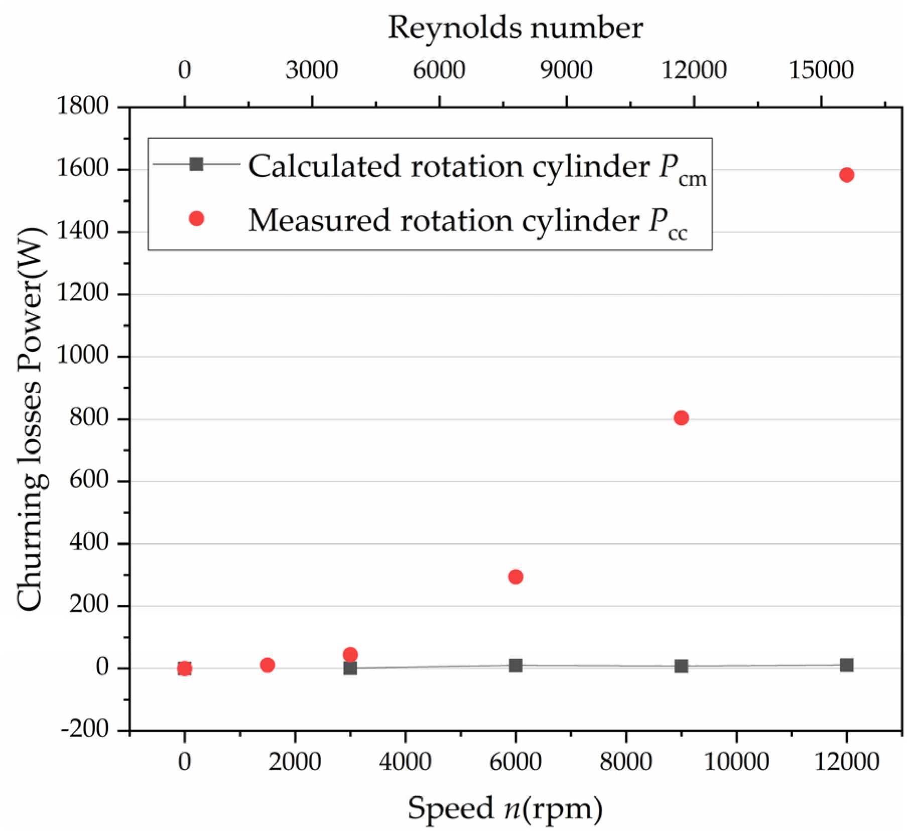
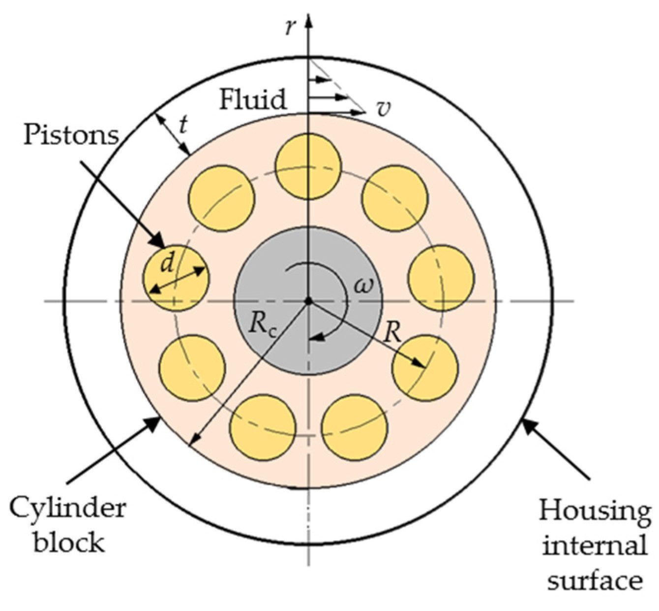
3.1. Churning Losses—Formulas for the Cylinder Block
3.2. Churning Losses—Formulas for Pistons
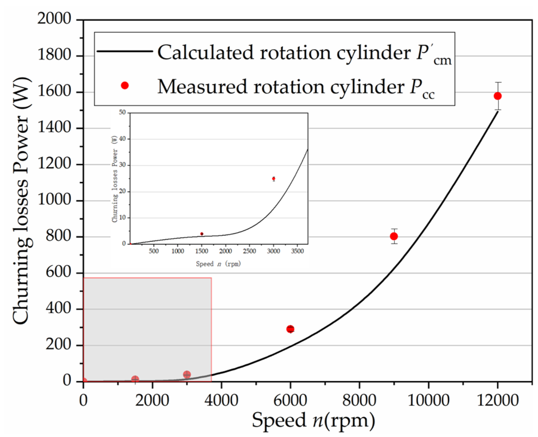
4. Discussion
5. Conclusions
Author Contributions
Funding
Conflicts of Interest
Nomenclature
| d | the diameter of the piston (m) |
| Cd | the drag coefficient |
| kz | the reduction coefficient |
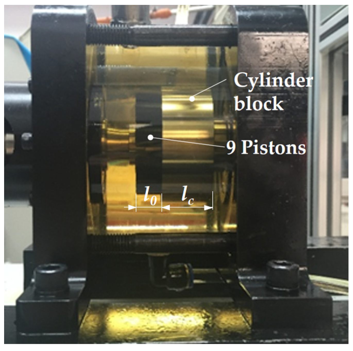
| l0 | the length of the piston out of the cylinder block at the outer dead point (m) |
| lc | the length of the cylinder block (m) |
| Mcc | the experimental churning losses torque due to the rotation of the cylinder (N·m) |
| Mcp | the experimental churning losses torque due to the circling pistons (N·m) |
| Mdc | the experimental torque acting on the shaft because of the rotation of the cylinder without oil in the case (N·m) |
| Mdcp | the experimental torque acting on the shaft because of the circling pistons and the rotating cylinder without oil in the case (N·m) |
| Mwc | the experimental torque acting on the shaft because of the rotation of the cylinder with oil in the case (N·m) |
| Mwcp | the experimental torque acting on the shaft because of the circling pistons and the rotating cylinder with oil in the case (N·m) |
| n | the test speed (rpm) |
| Pcc | the experimental churning losses power due to the rotation of the cylinder (W) |
| Pcm | the calculated churning losses power due to the rotation of the cylinder (W) |
| P’cm | the calculated churning losses power due to the rotation of the cylinder after optimization (W) |
| Pcp | the experimental churning losses power due to circling pistons (W) |
| Ppm | the calculated churning losses power due to circling pistons (W) |
| P’pm | the calculated churning losses power due to circling pistons after optimization (W) |
| R | the pitch circle radius of piston bores (m) |
| Rc | the radius of the cylinder block (m) |
| Re | the Reynolds number |
| t | the gap between the cylinder block and the housing internal surface(m) |
| V | the volume of the stirring oil (m3) |
| z | the number of pistons |
| ω | the rotation angular velocity (rad/s) |
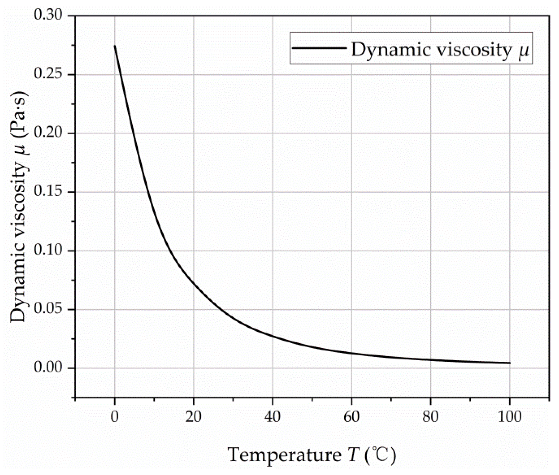
| μ | the dynamic viscosity (Pa·s) |
| ρ | the density of test fluid (kg/m3) |
| γ | the swash plate angle (rad) |
References
- Yang, H.; Pan, M. Engineering research in fluid power: A review. J. Zhejiang Univ. Sci. A 2015, 16, 427–442. [Google Scholar] [CrossRef]
- Yang, H.; Zhang, B.; Xu, B. Development of axial piston pump/motor technology. Chin. J. Mech. Eng. 2008, 44, 1–8. [Google Scholar] [CrossRef]
- Zhang, J.; Li, Y.; Xu, B.; Pan, M.; Lv, F. Experimental study on the influence of the rotating cylinder block and pistons on churning losses in axial piston pumps. Energies 2017, 10, 662. [Google Scholar] [CrossRef]
- Darbani, A.A.; Shang, L.; Beale, J.R.; Ivantysynova, M. Slipper Surface Geometry Optimization of the Slipper/Swashplate Interface of Swashplate-Type Axial Piston Machines. Int. J. Fluid Power 2019, 20, 245–270. [Google Scholar] [CrossRef]
- Hasko, D.; Shang, L.; Noppe, E.; Lefrançois, E. Virtual Assessment and Experimental Validation of Power Loss Contributions in Swash Plate Type Axial Piston Pumps. Energies 2019, 12, 3096. [Google Scholar] [CrossRef]
- Jang, D.S. Verlustanalyse an Axialkolbeneinheiten. Ph.D. Thesis, RWTH Aachen University, Aachen, German, 1997. [Google Scholar]
- Xu, B.; Li, Y.; Zhang, J.; Chao, Q. Modeling and analysis of the churning losses characteristics of swash plate axial piston pump. In Proceedings of the IEEE 2015 International Conference on Fluid Power and Mechatronics (FPM), Harbin, China, 5–7 August 2015; pp. 22–26. [Google Scholar]
- Theissen, H.; Gels, S.; Murrenhoff, H. Reducing energy losses in hydraulic pumps. In Proceedings of the 9th International Conference on Fluid Power Transmission and Control (ICFP), Hangzhou, China, 9–11 April 2013; pp. 1–6. [Google Scholar]
- Enekes, C.P. Ausgewählte Maßnahmen zur Effizienzsteigerung von Axialkolbenmaschinen. Ph.D. Thesis, RWTH Aachen University, Aachen, German, 2012. [Google Scholar]
- Shang, L.; Ivantysynova, M. Port and case flow temperature prediction for axial piston machines. Int. J. Fluid Power 2015, 16, 35–51. [Google Scholar]
- Rahmfeld, R.; Marsch, S.; Göllner, W.; Lang, T.; Dopichay, T.; Untch, J. Efficiency potential of dry case operation for bent-axis motors. In Proceedings of the 8th International Fluid Power Conference (IFK), Dresden, German, 26–28 March 2012; pp. 26–28. [Google Scholar]
- Rahmfeld, R.; Marsch, S.; Göllner, W.; Lang, T.; Dopichay, T.; Untch, J. Mehr Effizienz bei hydrostatischen Einheiten. Oil Hydraul. Pneum. 2012, 56, 7–8. [Google Scholar]
- Jing, C.B.; Zhou, J.J.; Zhou, J.C. Experimental study of churning losses in swash plate axial piston pump. J. Beijing Inst. Technol. 2019, 28, 529–535. [Google Scholar]
- Moslått, G.A.; Hansen, M.R.; Karlsen, N.S. A model for torque losses in variable displacement axial piston motors. MIC 2018, 39, 107–114. [Google Scholar] [CrossRef]
- Huang, Y.; Ding, C.; Wang, H.; Ruan, J. Numerical and experimental study on the churning losses of 2D high-speed piston pumps. Eng. Appl. Comput. Fluid Mech. 2020, 14, 764–777. [Google Scholar] [CrossRef]
- Ding, C.; Huang, Y.; Zhang, L.; Ruan, J. Investigation of the Churning Loss Reduction in 2D Motion-Converting Mechanisms. Energies 2021, 14, 1506. [Google Scholar] [CrossRef]
- Huang, Y.; Ruan, J.; Zhang, C.; Ding, C.; Li, S. Research on the Mechanical Efficiency of High-Speed 2D Piston Pumps. Processes 2020, 8, 853. [Google Scholar] [CrossRef]
- Thiagarajan, D.; Vacca, A. Investigation of Hydro-Mechanical Losses in External Gear Machines: Simulation and Experimental Validation. In Proceedings of the BATH/ASME 2016 Symposium on Fluid Power and Motion Control, Bath, UK, 7–9 September 2016. [Google Scholar]
- Thiagarajan, D.; Vacca, A. Mixed Lubrication Effects in the Lateral Lubricating Interfaces of External Gear Machines: Modelling and Experimental Validation. Energies 2017, 10, 111. [Google Scholar] [CrossRef]
- Changenet, C.; Leprince, G.; Ville, F.; Velex, P. A Note on Flow Regimes and Churning Loss Modeling. ASME J. Mech. Des. 2011, 133, 121009. [Google Scholar] [CrossRef]
- Xu, B.; Chao, Q.; Zhang, J.; Chen, Y. Effects of the dimensional and geometrical errors on the cylinder block tilt of a high-speed EHA pump. Meccanica 2017, 52, 2449–2469. [Google Scholar] [CrossRef]
- Zecchi, M.; Mehdizadeh, A.; Ivantysynova, M. A novel approach to predict the steady state temperature in ports and case of swash plate type axial piston machines. In Proceedings of the 13th Scandinavian International Conference on Fluid Power (SICFP), Linköping, Sweden, 3–5 June 2013; pp. 177–187. [Google Scholar]
- Zdravkovich, M.M. REVIEW—Review of flow interference between two circular cylinders in various arrangements. J. Fluids Eng. 1977, 99, 618–633. [Google Scholar] [CrossRef]
- Zdravkovich, M.M. Flow induced oscillations of two interfering circular cylinders. J. Sound Vib. 1985, 101, 511–521. [Google Scholar] [CrossRef]
- Igarashi, T. Characteristics of the flow around two circular cylinders arranged in tandem: 1st report. Bull. JSME 1981, 24, 323–331. [Google Scholar] [CrossRef]
- Kim, S.; Alam, M.M. Characteristics and suppression of flow-induced vibrations of two side-by-side circular cylinders. J. Fluids Struct. 2015, 54, 629–642. [Google Scholar] [CrossRef]
- Deng, S.Y. Numerical and Experimental Study on the Churning Losses of 2D High-Speed Piston Pumps. Ph.D. Thesis, Nanjing Hydraulic Research Institute, Nanjing, China, June 2007. [Google Scholar]
- Ivantysyn, J.; Ivantysynova, M. Hydrostatic Pumps and Motors: Principles, Design, Performance, Modelling, Analysis, Control and Testing; Academic Books International: New Delhi, India, 2001. [Google Scholar]


| Parameters | Value |
|---|---|
| The number of pistons z | 9 |
| The diameter of the piston d (m) | 0.01 |
| The pitch circle radius of the piston bores R (m) | 0.02 |
| The radius of the cylinder block Rc (m) | 0.028 |
| The length of the piston out of the cylinder block at the outer dead point l0 (m) | 0.0165 |
| The length of the cylinder block lc (m) | 0.0325 |
| The gap between the cylinder block and the housing internal surface t (m) | 0.0145 |
| Test speed n (rpm) | 1500/3000/6000/9000/12,000 |
| Dynamic viscosity μ (Pa·s) | 0.0278 |
| Density of the test fluid ρ (kg/m3) | 850 |
| Speed | kz |
|---|---|
| 1500 rpm | −0.0072 |
| 3000 rpm | −0.0471 |
| 6000 rpm | −0.0783 |
| 9000 rpm | −0.0930 |
| 12,000 rpm | −0.1001 |
Publisher’s Note: MDPI stays neutral with regard to jurisdictional claims in published maps and institutional affiliations. |
© 2021 by the authors. Licensee MDPI, Basel, Switzerland. This article is an open access article distributed under the terms and conditions of the Creative Commons Attribution (CC BY) license (https://creativecommons.org/licenses/by/4.0/).
Share and Cite
Li, Y.; Chen, X.; Luo, H.; Zhang, J. An Empirical Model for the Churning Losses Prediction of Fluid Flow Analysis in Axial Piston Pumps. Micromachines 2021, 12, 398. https://doi.org/10.3390/mi12040398
Li Y, Chen X, Luo H, Zhang J. An Empirical Model for the Churning Losses Prediction of Fluid Flow Analysis in Axial Piston Pumps. Micromachines. 2021; 12(4):398. https://doi.org/10.3390/mi12040398
Chicago/Turabian StyleLi, Ying, Xing Chen, Hao Luo, and Jin Zhang. 2021. "An Empirical Model for the Churning Losses Prediction of Fluid Flow Analysis in Axial Piston Pumps" Micromachines 12, no. 4: 398. https://doi.org/10.3390/mi12040398
APA StyleLi, Y., Chen, X., Luo, H., & Zhang, J. (2021). An Empirical Model for the Churning Losses Prediction of Fluid Flow Analysis in Axial Piston Pumps. Micromachines, 12(4), 398. https://doi.org/10.3390/mi12040398