
A Novel Impedance Micro-Sensor for Metal Debris Monitoring of Hydraulic Oil


 ,
,
Abstract
1. Introduction
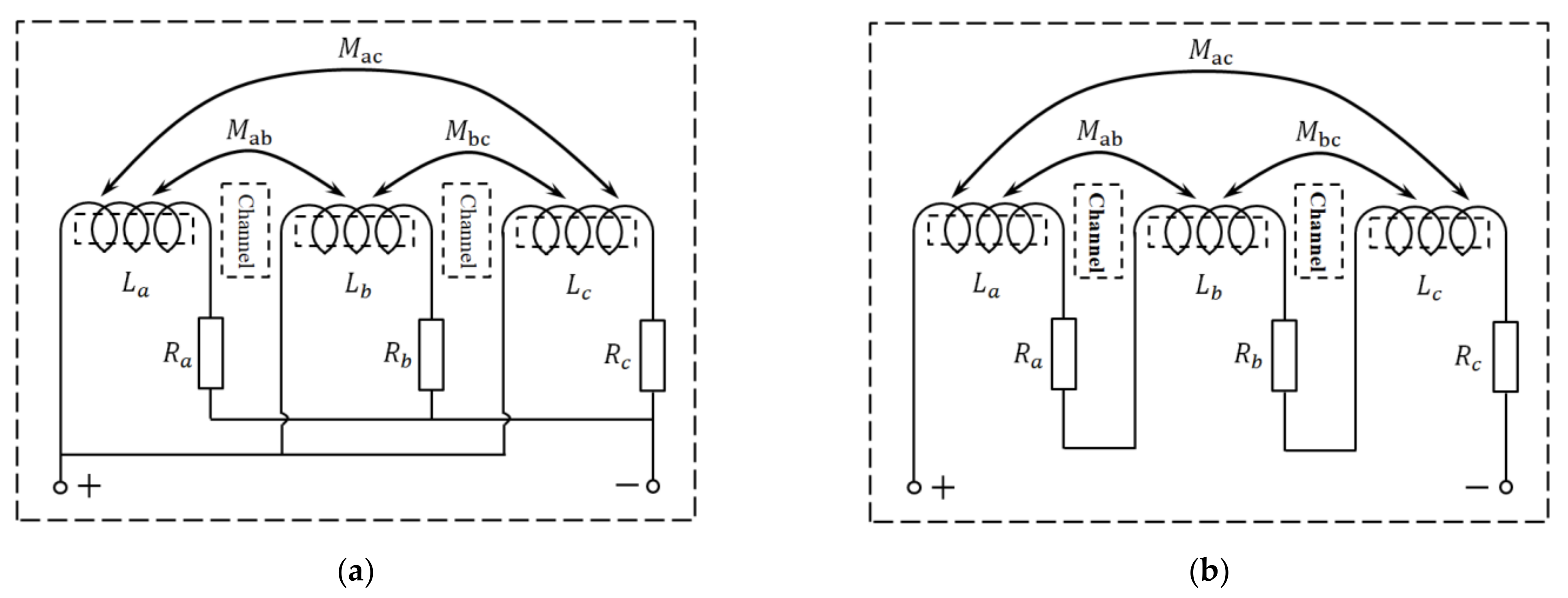
2. Sensor Design
3. Detection Principle
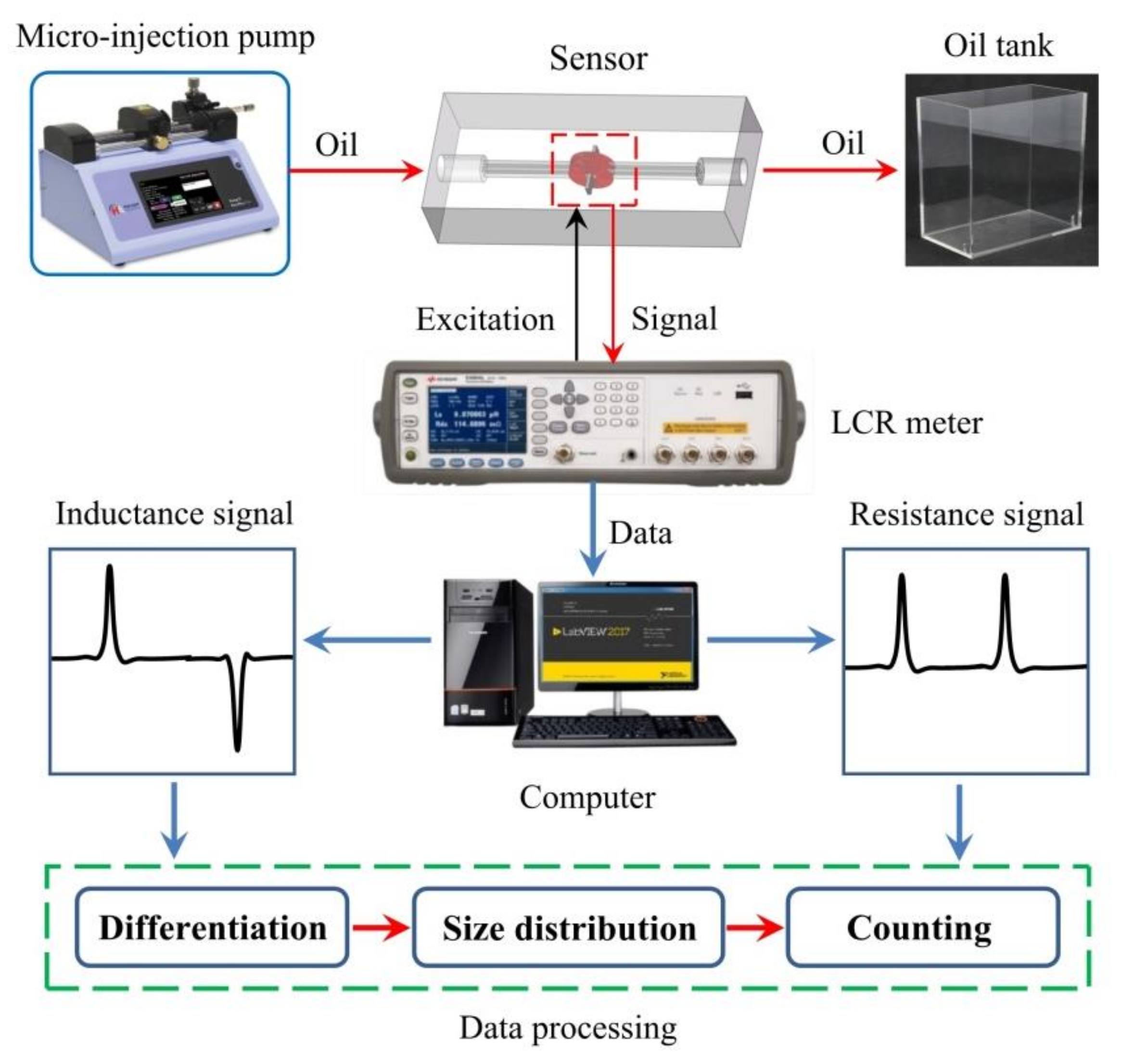
4. Impedance Detection System
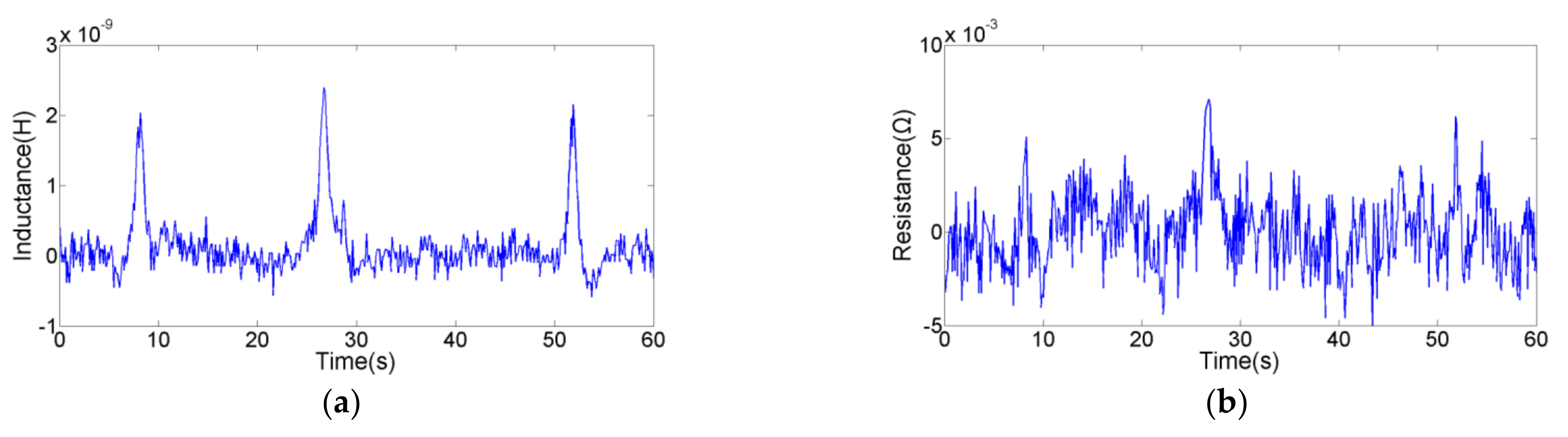
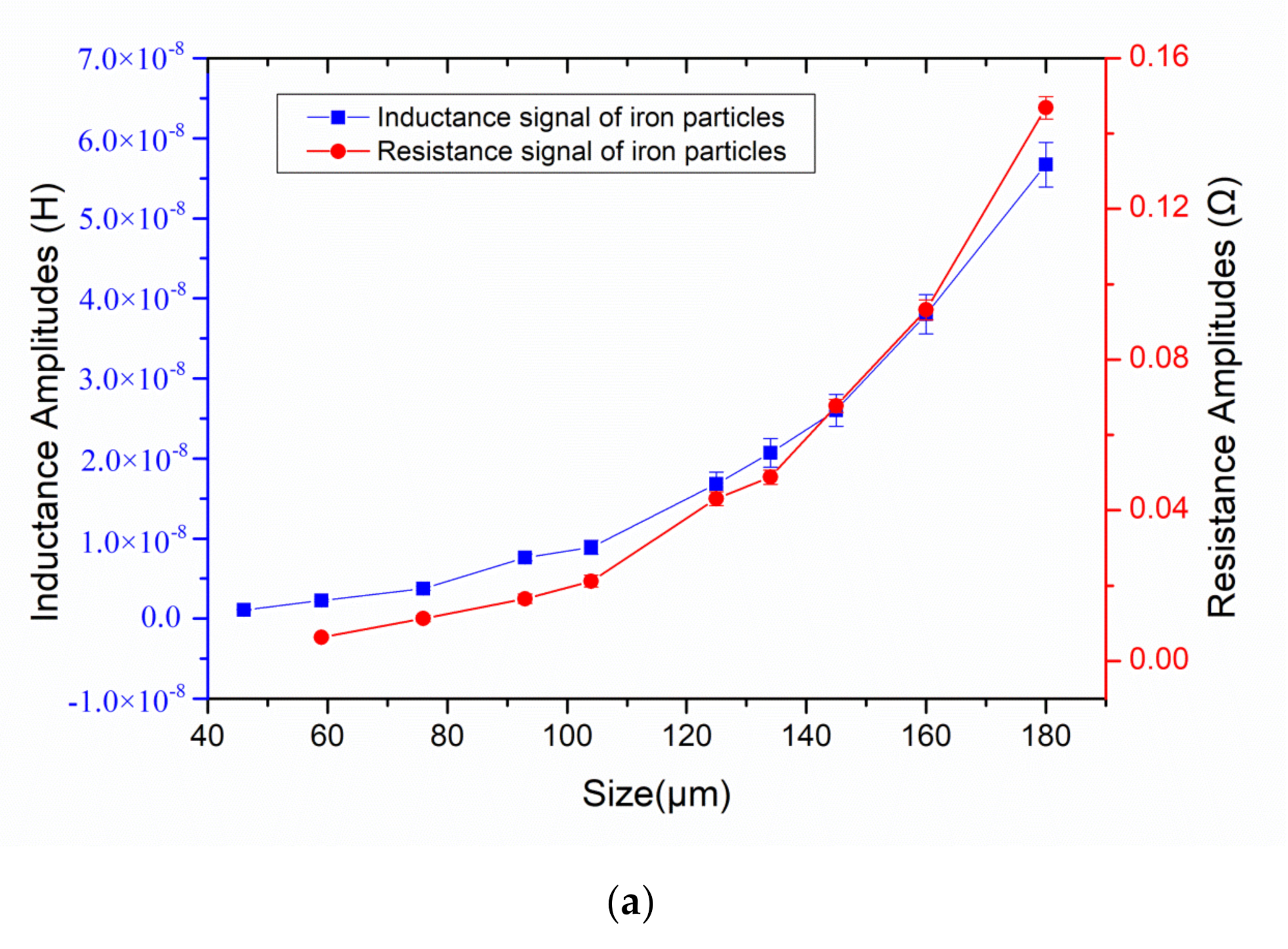
5. Experiments
6. Conclusions
Author Contributions
Funding
Institutional Review Board Statement
Informed Consent Statement
Data Availability Statement
Conflicts of Interest
References
- Kumar, M.; Mukherjee, P.S.; Misra, N.M. Advancement and current status of wear debris analysis for machine condition monitoring: A review. Ind. Lubr. Tribol. 2013, 65, 3–11. [Google Scholar] [CrossRef]
- Huang, Z.Y.; Yu, Z.Q.; Li, Z.X.; Geng, Y.C. A Fault Diagnosis Method of Rolling Bearing through Wear Particle and Vibration Analyses. Appl. Mech. Mater. 2010, 26, 676–681. [Google Scholar] [CrossRef]
- Peng, Y.; Wu, T.; Wang, S.; Peng, Z. Wear state identification using dynamic features of wear debris for on-line purpose. Wear 2017, 376, 1885–1891. [Google Scholar] [CrossRef]
- Cao, W.; Dong, G.; Xie, Y.-B.; Peng, Z. Prediction of wear trend of engines via on-line wear debris monitoring. Tribol. Int. 2018, 120, 510–519. [Google Scholar] [CrossRef]
- Abdul-Munaim, A.M.; Reuter, M.; Abdulmunem, O.M.; Balzer, J.C.; Koch, M.; Watson, D.G. Using Terahertz Time-Domain Spectroscopy to Discriminate among Water Contamination Levels in Diesel Engine Oil. Trans. ASABE 2016, 59, 795–801. [Google Scholar]
- Wang, H.T.; Gong, L.H.; Zhao, W.; Zhao, H.F. Study on Mechanical Wear State in Military Launch Vehicle Hydraulic System with Knowledge Discovery from Analytical Ferrography. Appl. Mech. Mater. 2013, 454, 94–97. [Google Scholar] [CrossRef]
- Mabe, J.; Zubia, J.; Gorritxategi, E. Lens-free imaging-based low-cost microsensor for in-line wear debris detection in lube oils. In Proceedings of the SPIE OPTO 2017—Photonic Instrumentation Engineering IV, San Francisco, CA, USA, 31 January–2 February 2017. [Google Scholar] [CrossRef]
- Lopez, P.; Mabe, J.; Miró, G.; Etxeberria, L. Low Cost Photonic Sensor for in-Line Oil Quality Monitoring: Methodological Development Process towards Uncertainty Mitigation. Sensors 2018, 18, 2015. [Google Scholar] [CrossRef]
- Xu, C.; Zhang, P.; Wang, H.; Li, Y.; Lv, C. Ultrasonic echo waveshape features extraction based on QPSO-matching pursuit for online wear debris discrimination. Mech. Syst. Signal Process. 2015, 60, 301–315. [Google Scholar] [CrossRef]
- Xu, C.; Zhang, P.; Ren, G.; Li, B.; Wu, D.; Fan, H. Discriminating debris particle in lubricant by ultrasonic waveshape features. Ind. Lubr. Tribol. 2015, 67, 202–209. [Google Scholar] [CrossRef]
- Shi, H.; Ma, L.; Rogers, F.; Zhao, X.; Zeng, L. An Impedance Debris Sensor Based on a High-Gradient Magnetic Field for High Sensitivity and High Throughput. IEEE Trans. Ind. Electron. 2020. [Google Scholar] [CrossRef]
- Zhu, X.; Du, L.; Zhe, J. An integrated lubricant oil conditioning sensor using signal multiplexing. J. Micromechan. Microeng. 2014, 25. [Google Scholar] [CrossRef]
- Islam, T.; Yousuf, M.; Nauman, M. A highly precise cross-capacitive sensor for metal debris detection in insulating oil. Rev. Sci. Instrum. 2020, 91, 025005. [Google Scholar] [CrossRef] [PubMed]
- Shi, H.; Zhang, H.; Wang, W.; Zeng, L.; Sun, G.; Chen, H. An Integrated Inductive-Capacitive Microfluidic Sensor for Detection of Wear Debris in Hydraulic Oil. IEEE Sens. J. 2019, 19, 11583–11590. [Google Scholar] [CrossRef]
- Miller, J.L.; Kitaljevich, D. In-line oil debris monitor for aircraft engine condition assessment. In Proceedings of the 2000 IEEE Aerospace Conference, Big Sky, MT, USA, 25 March 2000; pp. 49–56. [Google Scholar]
- Bozchalooi, I.S.; Liang, M. In-line identification of oil debris signals: An adaptive subband filtering approach. Meas. Sci. Technol. 2009, 21, 015104. [Google Scholar] [CrossRef]
- Hong, W.; Wang, S.; Liu, H.; Tomovć, M.M.; Zhang, C. A hybrid method based on Band Pass Filter and Correlation Algorithm to improve debris sensor capacity. Mech. Syst. Signal Process. 2017, 82, 1–12. [Google Scholar] [CrossRef]
- Ren, Y.J.; Zhao, G.F.; Qian, M.; Feng, Z.H. A highly sensitive triple-coil inductive debris sensor based on an effective unbalance compensation circuit. Meas. Sci. Technol. 2018, 30, 015108. [Google Scholar] [CrossRef]
- Jia, R.; Ma, B.; Zheng, C.; Ba, X.; Wang, L.; Du, Q.; Wang, K. Comprehensive Improvement of the Sensitivity and Detectability of a Large-Aperture Electro-magnetic Wear Particle Detector. Sensors 2019, 19, 3162. [Google Scholar] [CrossRef]
- Ding, Y.; Wang, Y.; Xiang, J. An online debris sensor system with vibration resistance for lubrication analysis. Rev. Sci. Instrum. 2016, 87, 025109. [Google Scholar] [CrossRef]
- Ren, Y.J.; Li, W.; Zhao, G.F.; Feng, Z.H. Inductive debris sensor using one energizing coil with multiple sensing coils for sensitivity im-provement and high throughput. Tribol. Int. 2018, 128, 96–103. [Google Scholar] [CrossRef]
- Xiao, H.; Wang, X.; Li, H.; Luo, J.; Feng, S. An Inductive Debris Sensor for a Large-Diameter Lubricating Oil Circuit Based on a High-Gradient Magnetic Field. Appl. Sci. 2019, 9, 1546. [Google Scholar] [CrossRef]
- Hong, W.; Wang, S.; Tomovic, M.; Liu, H.; Wang, X. A new debris sensor based on dual excitation sources for online debris monitoring. Meas. Sci. Technol. 2015, 26. [Google Scholar] [CrossRef]
- Du, L.; Zhe, J.; Carletta, J.; Veillette, R.; Choy, F. Real-time monitoring of wear debris in lubrication oil using a microfluidic inductive Coulter counting device. Microfluid. Nanofluidics 2010, 9, 1241–1245. [Google Scholar] [CrossRef]
- Ma, L.; Shi, H.; Zhang, H.; Li, G.; Shen, Y.; Zeng, N. High-sensitivity distinguishing and detection method for wear debris in oil of marine machinery. Ocean Eng. 2020, 215, 107452. [Google Scholar] [CrossRef]
- Liu, L.; Chen, L.; Wang, S.; Yin, Y.; Liu, D.; Wu, S.; Liu, Z.; Pan, X. Improving Sensitivity of a Micro Inductive Sensor for Wear Debris Detection with Magnetic Powder Surrounded. Micromachines 2019, 10, 440. [Google Scholar] [CrossRef] [PubMed]
- Zhang, H.; Zeng, L.; Teng, H.; Zhang, X. A Novel On-Chip Impedance Sensor for the Detection of Particle Contamination in Hydraulic Oil. Micromachines 2017, 8, 249. [Google Scholar] [CrossRef] [PubMed]
- Zeng, L.; Wang, W.; Rogers, F.; Zhang, H.; Zhang, X.; Yang, D. A High Sensitivity Micro Impedance Sensor Based on Magnetic Focusing for Oil Condition Monitoring. IEEE Sens. J. 2019, 20, 3813–3821. [Google Scholar] [CrossRef]
- Zhang, X.; Zeng, L.; Zhang, H.; Huang, S. Magnetization Model and Detection Mechanism of a Microparticle in a Harmonic Magnetic Field. IEEE/ASME Trans. Mechatron. 2019, 24, 1882–1892. [Google Scholar] [CrossRef]
- Shinagawa, H.; Suzuki, T.; Noda, M.; Shimura, Y.; Enoki, S.; Mizuno, T. Theoretical Analysis of AC Resistance in Coil Using Magnetoplated Wire. IEEE Trans. Magn. 2009, 45, 3251–3259. [Google Scholar] [CrossRef]
- Kazimierczuk, M.K.; Sancineto, G.; Grandi, G.; Reggiani, U.; Massarini, A. High-frequency small-signal model of ferrite core inductors. IEEE Trans. Magn. 1999, 35, 4185–4191. [Google Scholar] [CrossRef]
- Zhang, X.; Zhang, H.; Sun, Y.; Chen, H.; Zhang, Y. Research on the Output Characteristics of Microfluidic Inductive Sensor. J. Nanomater. 2014, 2014, 1–7. [Google Scholar] [CrossRef]
- Dziczkowski, L. Effect of eddy current frequency on measuring properties of devices used in non-destructive measurements of non-ferromagnetic metal plates. Arch. Mater. Sci. Eng. 2008, 32, 77–84. [Google Scholar]
- Wu, Y.; Zhang, H. Research on the effect of relative movement on the output characteristic of inductive sensors. Sens. Actuators A Phys. 2017, 267, 485–490. [Google Scholar] [CrossRef]
- Shi, H.; Zhang, H.; Ma, L.; Zeng, L. A multi-function sensor for online detection of contaminants in hydraulic oil. Tribol. Int. 2019, 138, 196–203. [Google Scholar] [CrossRef]


| Particle Type | Connection Mode | Inductance Pulse Amplitude/H | Inductance Signal Noise/H | Inductance SNR | Resistance Pulse Amplitude/Ω | Resistance Signal Noise/Ω | Resistance SNR |
|---|---|---|---|---|---|---|---|
| 93 μm iron particle | Series connection | 4.28 × 10⁻⁹ | 5.0 × 10⁻¹⁰ | 8.56 | 5.0 × 10⁻³ | ||
| Parallel connection | 9.4 × 10⁻¹¹ | 3.0 × 10⁻¹¹ | 3.13 | 3.0 × 10⁻⁴ | |||
| 186 μm copper particle | Series connection | 1.88 × 10⁻⁹ | 5.0 × 10⁻¹⁰ | 3.76 | 3.73 × 10⁻² | 5.0 × 10⁻³ | 7.46 |
| Parallel connection | 5.0 × 10⁻¹¹ | 3.0 × 10⁻¹¹ | 1.67 | 7.4 × 10⁻⁴ | 3.0 × 10⁻⁴ | 2.47 |
| Particle Type | Connection Mode | Inductance Pulse Amplitude/H | Inductance Signal Noise/H | Inductance SNR | Resistance Pulse Amplitude/Ω | Resistance Signal Noise/Ω | Resistance SNR |
|---|---|---|---|---|---|---|---|
| 93 μm iron particle | Series connection | 7.64 × 10⁻⁹ | 5.0 × 10⁻¹⁰ | 15.28 | 1.65 × 10⁻² | 5.0 × 10⁻³ | 3.30 |
| Parallel connection | 1.72 × 10⁻¹⁰ | 3.0 × 10⁻¹¹ | 5.73 | 4.7 × 10⁻⁴ | 3.0 × 10⁻⁴ | 1.57 | |
| 186 μm copper particle | Series connection | 5.63 × 10⁻⁹ | 5.0 × 10⁻¹⁰ | 11.26 | 8.03 × 10⁻² | 5.0 × 10⁻³ | 16.06 |
| Parallel connection | 1.05 × 10⁻¹⁰ | 3.0 × 10⁻¹¹ | 3.50 | 1.69 × 10⁻³ | 3.0 × 10⁻⁴ | 5.63 |
Publisher’s Note: MDPI stays neutral with regard to jurisdictional claims in published maps and institutional affiliations. |
© 2021 by the authors. Licensee MDPI, Basel, Switzerland. This article is an open access article distributed under the terms and conditions of the Creative Commons Attribution (CC BY) license (http://creativecommons.org/licenses/by/4.0/).
Share and Cite
Zhang, H.; Shi, H.; Li, W.; Ma, L.; Zhao, X.; Xu, Z.; Wang, C.; Xie, Y.; Zhang, Y. A Novel Impedance Micro-Sensor for Metal Debris Monitoring of Hydraulic Oil. Micromachines 2021, 12, 150. https://doi.org/10.3390/mi12020150
Zhang H, Shi H, Li W, Ma L, Zhao X, Xu Z, Wang C, Xie Y, Zhang Y. A Novel Impedance Micro-Sensor for Metal Debris Monitoring of Hydraulic Oil. Micromachines. 2021; 12(2):150. https://doi.org/10.3390/mi12020150
Chicago/Turabian StyleZhang, Hongpeng, Haotian Shi, Wei Li, Laihao Ma, Xupeng Zhao, Zhiwei Xu, Chenyong Wang, Yucai Xie, and Yuwei Zhang. 2021. "A Novel Impedance Micro-Sensor for Metal Debris Monitoring of Hydraulic Oil" Micromachines 12, no. 2: 150. https://doi.org/10.3390/mi12020150
APA StyleZhang, H., Shi, H., Li, W., Ma, L., Zhao, X., Xu, Z., Wang, C., Xie, Y., & Zhang, Y. (2021). A Novel Impedance Micro-Sensor for Metal Debris Monitoring of Hydraulic Oil. Micromachines, 12(2), 150. https://doi.org/10.3390/mi12020150