
Periodic Analysis of Surface Acoustic Wave Resonator with Dimensionally Reduced PDE Model Using COMSOL Code

 , ,
, , 
Abstract
1. Introduction
2. Methodology
2.1. COMSOL Multiphysics and Computation Procedure
2.2. Reduced PDE Modelling for Periodic Analysis
2.2.1. PDE-Based 2D-FEM Model
2.2.2. MOR Based on FEM
2.2.3. MOR Based on Anti-Periodic Boundary Condition
3. Numerical and Experimental Results
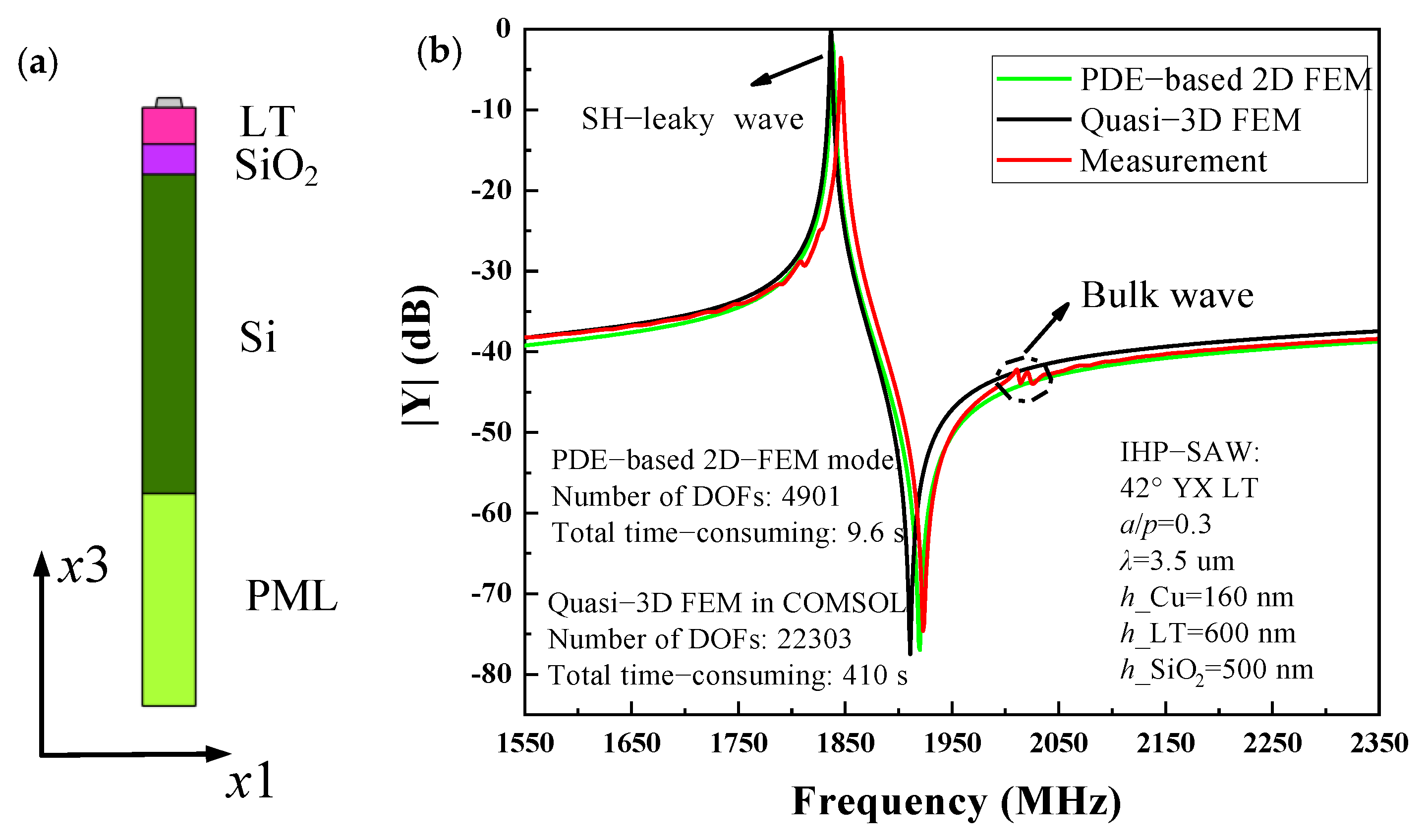
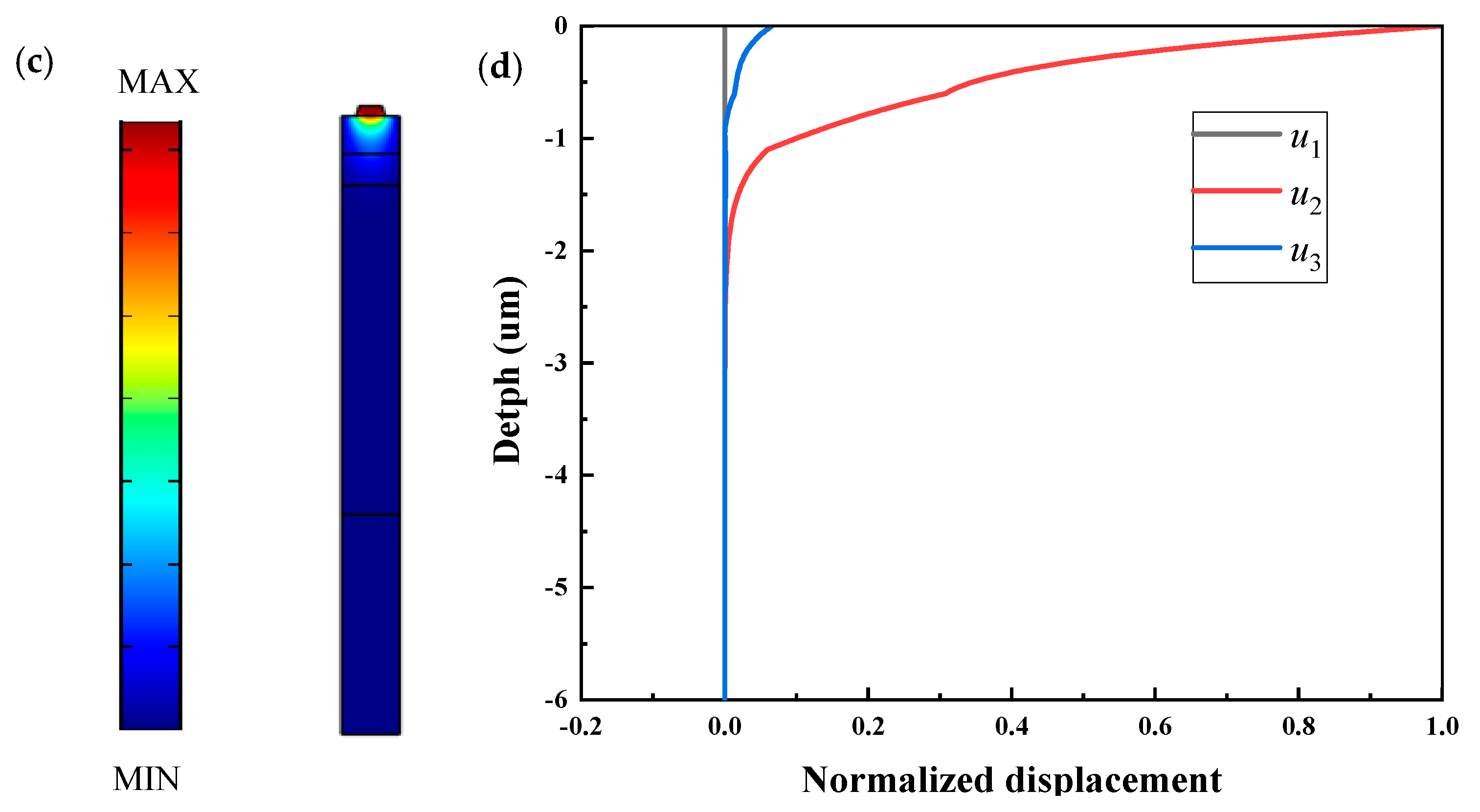
3.1. LT-Based SAW Resonator
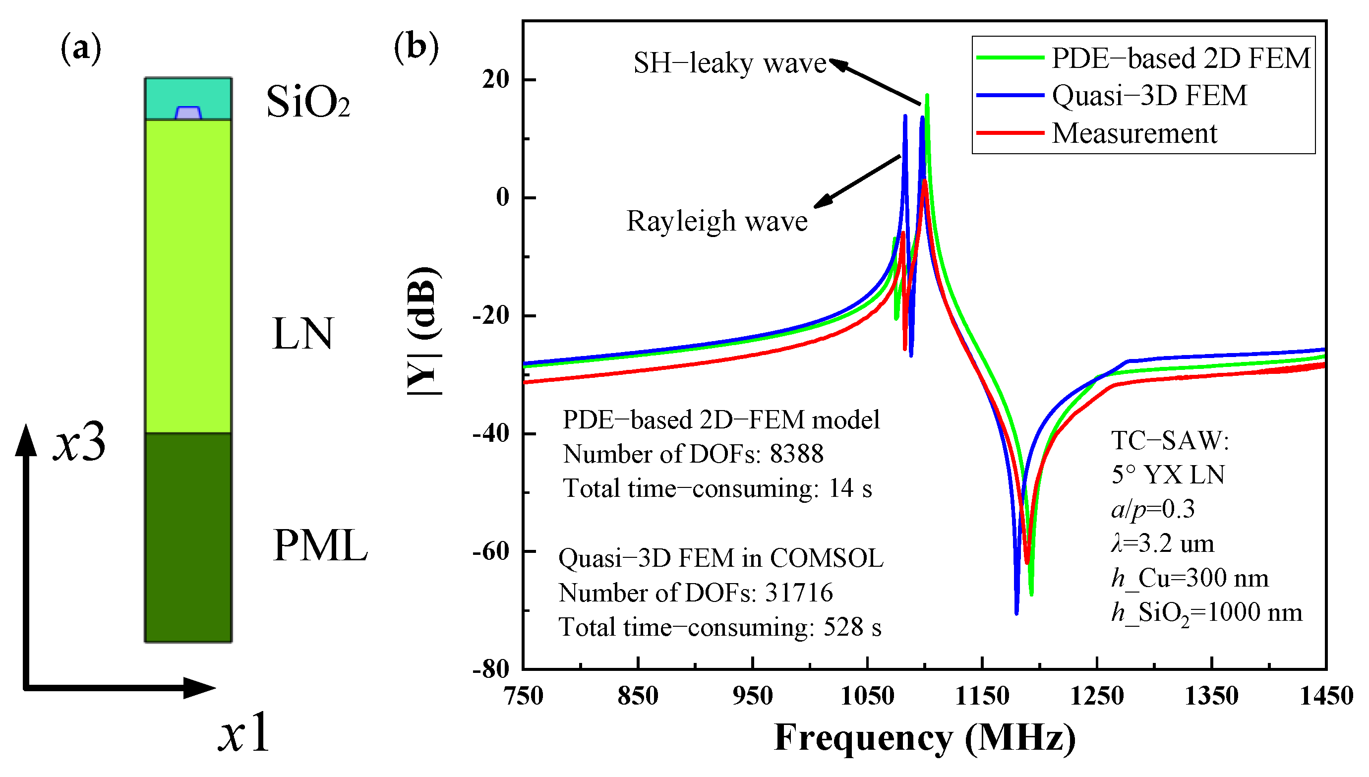
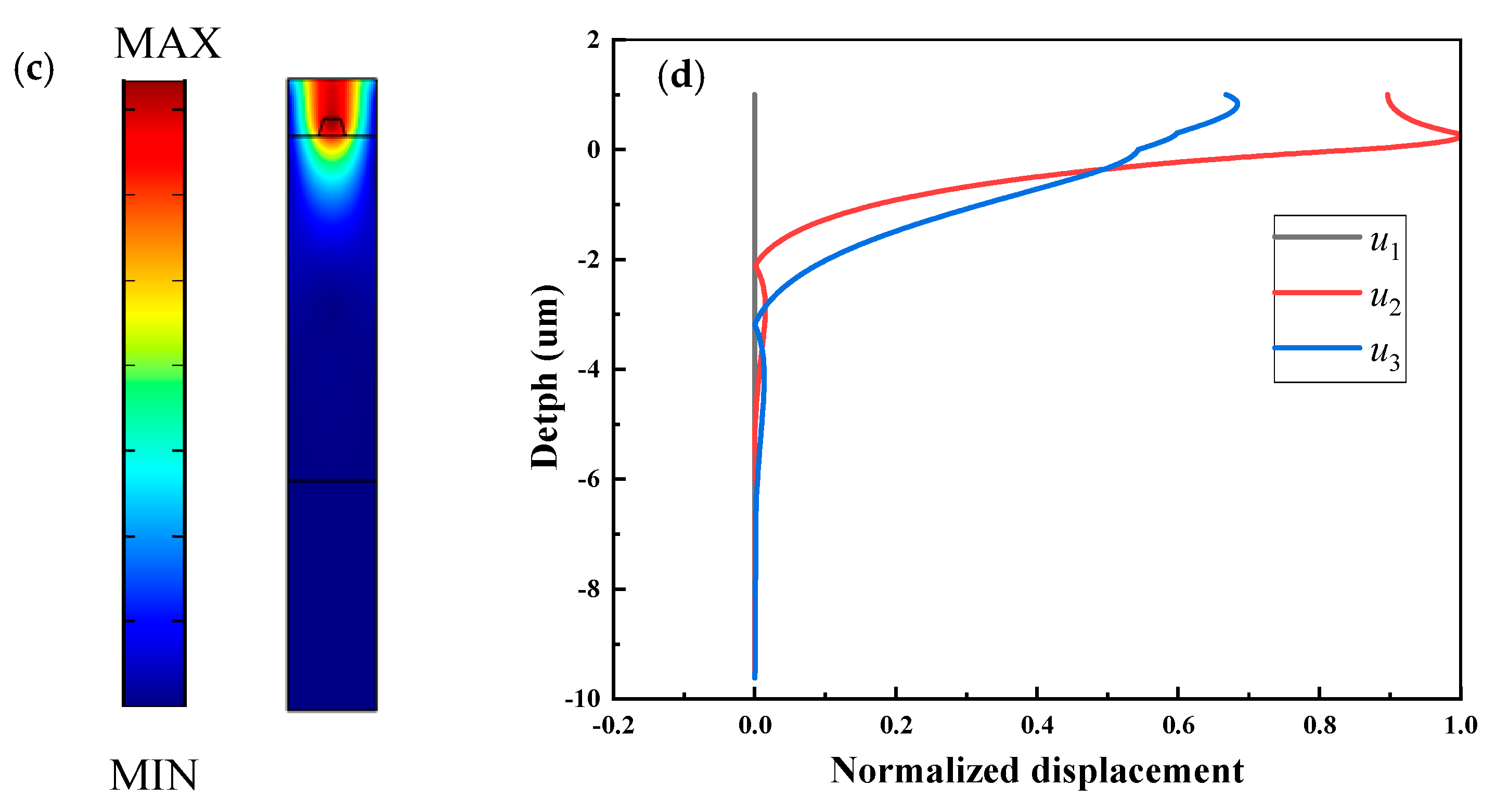
3.2. LN-Based SAW Resonator
3.3. Results Comparison and Discussions
4. Conclusions
Author Contributions
Funding
Conflicts of Interest
References
- Balysheva, O.L. SAW Filters for Mobile Communications: Achievements and Prospects. In Proceedings of the 2019 Wave Electronics and its Application in Information and Telecommunication Systems, Saint-Petersburg, Russia, 3–7 June 2019; pp. 1–4. [Google Scholar]
- Cai, T.; Chen, C.; Lin, F. A Hybrid Microstrip/SAW-Resonator Wideband Bandpass Filter. In Proceedings of the 2nd IEEE International Conference on Integrated Circuits, Technologies and Applications, Chengdu, China, 13–15 November 2019; pp. 127–128. [Google Scholar]
- Smirnov, D.; Plessky, V.; Miskinis, R.; Urba, E.; Yandrapalli, S. Network of SAW sensors with hyperbolically frequency-modulated reflecting gratings. In Proceedings of the IEEE International Ultrasonics Symposium (IUS), Las Vegas, NV, USA, 7–11 September 2020. [Google Scholar] [CrossRef]
- Chen, Z.; Zhang, Q.; Li, C.; Fu, S.; Qiu, X.; Wang, X.; Wu, H. Geometric nonlinear model for prediction of frequency temperature behavior of saw devices for nanosensor applications. Sensors 2020, 20, 4237. [Google Scholar] [CrossRef] [PubMed]
- Kajii, S.; Kong, D.; Nishio, K.; Kurosawa, M.K. Propulsion measurement of high frequency underwater SAW actuators. In Proceedings of the IEEE International Ultrasonics Symposium (IUS), Las Vegas, NV, USA, 7–11 September 2020. [Google Scholar] [CrossRef]
- Li, G.-Z.; Yu, J.-Y.; Liu, H.-P.; Chen, F.; Li, L.-X. Numerical simulation of effects of saw tooth plasma actuator on film cooling efficiency. J. Propuls. Technol. (Tuijin Jishu) 2017, 38, 2548–2554. [Google Scholar]
- Naumenko, N.F. Optimization of LiNbO3/Quartz substrate for high-frequency wideband SAW devices using longitudinal leaky waves. IEEE Trans. Ultrason. Ferroelectr. Freq. Control 2020, 67, 1485–1491. [Google Scholar] [CrossRef] [PubMed]
- Matsuoka, N.; Omori, T.; Hashimoto, K.-Y. Suppression of lowest-order plate mode in wafer-bonded saw devices using LiTaO3 thin plate. In Proceedings of the IEEE International Ultrasonics Symposium (IUS), Glasgow, UK, 7–11 September 2019; pp. 1231–1234. [Google Scholar]
- Pang, X.; Yong, Y.-K. Characteristics of BAW modes harmonically generated (f-2f-3f) in LiNO3 SAW devices. In Proceedings of the Joint Conference of the IEEE International Frequency Control Symposium and European Frequency and Time Forum, Orlando, FL, USA, 14–18 April 2019. [Google Scholar] [CrossRef]
- Hashimoto, K.; Sato, S.; Teshigahara, A.; Nakamura, T.; Kano, K. High-performance surface acoustic wave resonators in the 1 to 3 GHz range using a ScAlN/6H-SiC structure. IEEE Trans. Ultrason. Ferroelectr. Freq. Control 2013, 60, 637–642. [Google Scholar] [CrossRef] [PubMed]
- Tang, G.; Goto, R.; Nakamura, H. Modeling and suppression method for guided mode in TC-SAW devices. In Proceedings of the IEEE International Ultrasonics Symposium (IUS), Glasgow, UK, 6–9 October 2019; pp. 2087–2090. [Google Scholar]
- Abbott, B.; Kokkonen, K. Calculating transverse mode profiles of TCSAW piston mode resonators. In Proceedings of the IEEE International Ultrasonics Symposium (IUS), Tours, France, 18–21 September 2016; pp. 1–4. [Google Scholar]
- Mayer, M.; Ammann, S.; Pernpeintner, M.; Johnson, J.; Ebner, T.; Wagner, K. Multi-mode P-matrix models for the description of interacting modes in TCSAW and LSAW devices. In Proceedings of the IEEE International Ultrasonics Symposium (IUS), Kobe, Japan, 22–25 October 2018; pp. 1–4. [Google Scholar]
- Fu, S.; Wang, W.; Li, Q.; Lu, Z.; Chen, Z.; Luo, J.; Shen, J.; Wang, R.; Song, C.; Zeng, F. High-frequency V-doped ZnO/SiC surface acoustic wave devices with enhanced electromechanical coupling coefficient. Appl. Phys. Lett. 2019, 114, 113504.1–113504.5. [Google Scholar] [CrossRef]
- Takai, T.; Iwamoto, H.; Takamine, Y.; Fuyutsume, T.; Nakao, T.; Hiramoto, M.; Toi, T.; Koshino, M.I.H.P. SAW technology and its application to microacoustic components (Invited). In Proceedings of the IEEE International Ultrasonics Symposium (IUS), Washington, DC, USA, 6–9 September 2017; pp. 1–8. [Google Scholar]
- Plessky, V.; Yandrapalli, S.; Turner, P.J.; Villanueva, L.G.; Koskela, J.; Hammond, R.B. 5 GHz laterally-excited bulk-wave resonators (XBARs) based on thin platelets of lithium niobate. Electron. Lett. 2019, 55, 98–100. [Google Scholar] [CrossRef]
- Plessky, V.; Yandrapalli, S.; Turner, P.J.; Villanueva, L.G.; Koskela, J.; Faizan, M.; De Pastina, A.; Garcia, B.; Costa, J.; Hammond, R.B. Laterally excited bulk wave resonators (XBARs) based on thin Lithium Niobate platelet for 5GHz and 13 GHz filters. In Proceedings of the IEEE International Ultrasonics Symposium (IMS), Boston, MA, USA, 2–7 June; pp. 512–515.
- Takai, T.; Iwamoto, H.; Takamine, Y.; Yamazaki, H.; Fuyutsume, T.; Kyoya, H.; Nakao, T.; Kando, H.; Hiramoto, M.; Toi, T.; et al. Incredible high performance SAW resonator on novel multi-layerd substrate. In Proceedings of the IEEE International Ultrasonics Symposium (IUS), Tours, France, 18–21 September 2016; pp. 102–103. [Google Scholar]
- Glushkov, E.V.; Glushkova, N.V.; Evdokimov, A.A.; Zhang, C. Guided wave Generation in Elastic Layered Substrates with Piezoelectric Coatings and Patches. Phys. Procedia 2015, 70, 945–948. [Google Scholar] [CrossRef][Green Version]
- Su, R.; Fu, S.; Shen, J.; Chen, Z.; Lu, Z.; Yang, M.; Wang, R.; Zeng, F.; Wang, W.; Song, C.; et al. Enhanced performance of ZnO/SiO2/Al2O3 surface acoustic wave devices with embedded electrodes. ACS Appl. Mater. Interfaces 2020, 12, 42378–42385. [Google Scholar] [CrossRef] [PubMed]
- Perois, X.; Pastureaud, T.; Girard, P.A.; Lardat, R. Analysis of SAW devices using FEM/BEM method and parallel computing. In Proceedings of the IEEE International Ultrasonics Symposium, Rotterdam, The Netherlands, 18–21 September 2005; pp. 1564–1567. [Google Scholar]
- Ke, Y.; Li, H.; He, S. Fast FEM/BEM Simulation of non-periodic SAW structures. In Proceedings of the IEEE International Ultrasonics Symposium (IUS), Dresden, Germany, 7–10 October 2012; pp. 815–818. [Google Scholar]
- Li, H.; Lu, Z.; Ke, Y.; Tian, Y.; Luo, W. A fast optimization algorithm of FEM/BEM simulation for periodic surface acoustic wave structures. Information 2019, 10, 90. [Google Scholar] [CrossRef]
- Solal, M.; Chen, L.; Gratier, J. Measurement and FEM/BEM simulation of transverse effects in SAW resonators on lithium tantalate. IEEE Trans. Ultrason. Ferroelectr. Freq. Control 2013, 60, 2404–2413. [Google Scholar] [CrossRef] [PubMed]
- Shimko, A.; Plessky, V. Fast SAW Device Simulation in COMSOL Using the Hierarchical Cascading Method. In Proceedings of the IEEE International Ultrasonics Symposium (IUS), Glasgow, UK, 6–9 October 2019. [Google Scholar] [CrossRef]
- Solal, M.; Gallagher, M.; Tajic, A. Full 3D simulation of SAW resonators using hierarchical cascading FEM. In Proceedings of the 2017 IEEE International Ultrasonics Symposium (IUS), Washington, DC, USA, 6–9 September 2017; pp. 1–5. [Google Scholar]
- Koskela, J.; Plessky, V.; Willemsen, B.; Turner, P.; Hammond, B.; Fenzi, N. Hierarchical cascading algorithm for 2D FEM simulation of finite SAW devices. IEEE Trans. Ultrason. Ferroelectr. Freq. Control 2018, 65, 1933–1942. [Google Scholar] [CrossRef] [PubMed]
- Koskela, J.; Plessky, V.P.; Willemsen, B.A.; Turner, P.J.; Garcia, B.; Hammond, R.B.; Fenzi, N.O. Fast GPU-Assisted FEM Simulations of 3D Periodic TCSAW, IHP, and XBAR Devices. In Proceedings of the IEEE International Ultrasonics Symposium (IUS), Glasgow, UK, 6–9 October 2019; pp. 181–184. [Google Scholar]
- Wang, W.B.; Tang, K.J.; Wu, H.D. Analysis of frequency-temperature behavior of surface acoustic wave (SAW) under periodic IDT. In Proceedings of the Symposium on Piezoelectricity, Acoustic Waves and Device Applications, Xiamen, China, 10–13 December 2010; pp. 460–464. [Google Scholar]
- Yong, Y.-K. Analysis of periodic structures for BAW and SAW resonators. In Proceedings of the IEEE International Ultrasonics Symposium (IUS), Atlanta, GA, USA, 6–10 October 2001; pp. 781–790. [Google Scholar]
- Pastureaud, T.; Lardat, R.; Steichen, W.; Ventura, P. Analysis of SAW propagation under a periodic multi-electrode-type grating. In Proceedings of the IEEE International Ultrasonics Symposium (IUS), Rotterdam, The Netherlands, 18–21 September 2005; pp. 683–686. [Google Scholar]
- Huang, Y.; Bao, J.; Li, X.; Zhang, B.; Qiu, L.; Omori, T.; Hashimoto, K.-Y. Analysis of SAW scattering at discontinuity between periodic gratings using travelling wave excitation and hierarchical cascading technique. In Proceedings of the IEEE International Ultrasonics Symposium (IUS), Kobe, Japan, 22–25 October 2018; pp. 1–9. [Google Scholar]
- Pastureaud, T. Evaluation of the P-matrix parameters frequency variation using periodic FEM/BEM analysis. In Proceedings of the IEEE International Ultrasonics Symposium, Montreal, QC, Canada, 23–27 August 2004; pp. 645–649. [Google Scholar]
- Ventura, P.; Hecht, F.; Dufilie, P. Single electrode periodic buried IDT analysis using an original FEM/BEM numerical model. In Proceedings of the IEEE International Ultrasonics Symposium (IUS), San Diego, CA, USA, 11–14 October 2010; pp. 645–649. [Google Scholar]
- Fukuura, A.; Kawaguchi, M. A technique for P-matrix computation by periodic FEM/BEM analysis. In Proceedings of the IEEE International Ultrasonics Symposium (IUS), New York, NY, USA, 28–31 October 2007; pp. 694–697. [Google Scholar]
- Yantchev, V.; Turner, P.; Plessky, V. COMSOL modeling of SAW resonators. In Proceedings of the IEEE International Ultrasoics Symposium, Tours, France, 18–21 September 2016; pp. 1–4. [Google Scholar]
- Ten, S.T.; Hashim, U.; Liu, W.W.; Foo, K.L.; Voon, C.H.; Hisham, H.; Nazwa, T.; Ten, S.T.; Sudin, A.; Humaira, M.S.N. Shear Horizontal Surface Acoustic Wave COMSOL Modeling on Lithium Niobate Piezoelectric Substrate. In Proceedings of the IEEE International Conference on Semiconductor Electronics (ICSE), Kuala Lumpur, Malaysia, 27–29 August 2014; pp. 104–107. [Google Scholar]
- Yong, Y.K.; Kanna, S. IDT geometry and crystal cut effects on the frequency-temperature curves of a SAW periodic structure of quartz. Ultrason 1998, 1, 223–228. [Google Scholar]
- Yong, Y.K. Three-Dimensional Finite-Element Solution of the Lagrangean Equations for the Frequency-Temperature Behavior of Y-Cut and NT-Cut Bars. IEEE Trans. Ultrason. Ferroelectr. Freq. Control 1987, 34, 491–499. [Google Scholar] [CrossRef] [PubMed]
- Zhang, Q.; Han, T.; Tang, G.; Chen, J.; Hashimoto, K. SAW Characteristics of AlN/SiO2/3C-SiC Layered Structure With Embedded Electrodes. IEEE Trans. Ultrason. Ferroelectr. Freq. Control 2016, 63, 1608–1612. [Google Scholar] [CrossRef] [PubMed]
- Chen, Z.; Zhang, Q.; Fu, S.; Wang, X.; Qiu, X.; Wu, H. Hybrid full-wave analysis of surface acoustic wave devices for accuracy and fast performance prediction. Micromachines 2021, 12, 5. [Google Scholar] [CrossRef] [PubMed]
- Fotyga, G.; Nyka, K.; Kulas, L. Macro-elements and model order reduction for efficient three-dimensional FEM analysis. In Proceedings of the 2012 19th International Conference on Microwaves, Radar and Wireless Communications, Warsaw, Poland, 21–23 May 2012; pp. 137–140. [Google Scholar]
- Xoubi, N.; Soliman, A.Y. Neutronic modeling and calculations of the ETRR-2 MTR reactor using COMSOL multiphysics code. Ann. Nucl. Energy 2017, 109, 667–674. [Google Scholar] [CrossRef]
- Sahu, S.; Bhattacharyay, R. Validation of COMSOL code for analyzing liquid metal magnetohydrodynamic flow. Fusion Eng. Des. 2018, 127, 151–159. [Google Scholar] [CrossRef]
- Qiao, D.; Liu, W.; Smith, P.M. General Green’s functions for SAW device analysis. IEEE Trans. Ultrason. Ferroelectr. Freq. Control 1999, 46, 1242–1253. [Google Scholar] [CrossRef] [PubMed]
- COMSOL Multiphysics LiveLink for MATLAB User’s Guides. Available online: https://cn.comsol.com/documentation (accessed on 7 January 2019).
- Zou, J.; Yantchev, V.; Iliev, F.; Plessky, V.; Samadian, S.; Hammond, R.B.; Turner, P.J. Ultra-Large-Coupling and Spurious-Free SH0 Plate Acoustic Wave Resonators Based on Thin LiNbO3. IEEE Trans. Ultrason. Ferroelectr. Freq. Control 2020, 67, 374–386. [Google Scholar] [CrossRef] [PubMed]
- Kovacs, G.; Anhorn, M.; Engan, H.E.; Visintini, G.; Ruppel, C.C.W. Improved material constants for LiNbO3 and LiTaO3. In Proceedings of the IEEE International Ultrasonics Symposium, Honolulu, HI, USA, 4–7 December 1990; pp. 435–438. [Google Scholar]
- Fu, S.; Wang, W.; Qian, L.; Li, Q.; Lu, Z.; Shen, J.; Song, C.; Zeng, F.; Pan, F.; Parker, R.; et al. High-Frequency Surface Acoustic Wave Devices Based on ZnO/SiC Layered Structure. IEEE Electron Device Lett. 2019, 40, 103–106. [Google Scholar] [CrossRef]


| Parameters | Normal SAW | IHP SAW | TC SAW | ||||||
|---|---|---|---|---|---|---|---|---|---|
| S | M | Error | S | M | Error | S | M | Error | |
| K2 | 9.64% | 9.31% | 3.42% | 10.53% | 10.28% | 2.37% | 18.82% | 18.51% | 1.65% |
| Q | 549.18 | 551 | 0.33% | 1011 | 986.8 | 2.39% | 976.1 | 947.96 | 2.88% |
| FEM Model | Normal SAW | IHP SAW | TC SAW | ||||||
|---|---|---|---|---|---|---|---|---|---|
| DOFs | T1 (s) | T2(s) (950–1300 MHz) | DOFs | T1 (s) | T2(s) (1550–2350 MHz) | DOFs | T1 (s) | T2 (s) (750–1450 MHz) | |
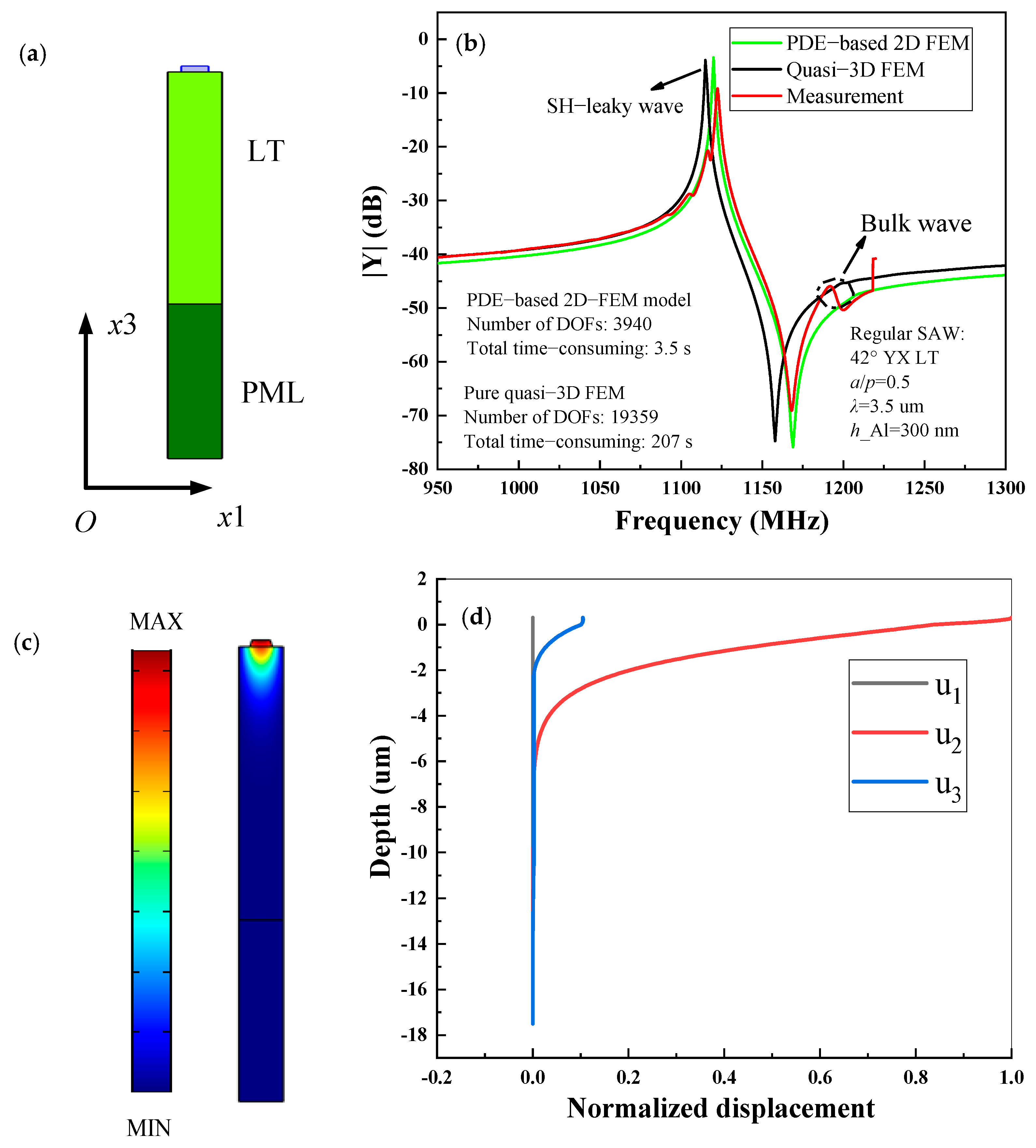
| PDE | 3940 | 0.01 | 3.5 | 4901 | 0.012 | 9.6 | 8388 | 0.02 | 14 |
| Quasi-3D | 19359 | 0.59 | 207 | 22303 | 0.51 | 410 | 31716 | 0.75 | 528 |
Publisher’s Note: MDPI stays neutral with regard to jurisdictional claims in published maps and institutional affiliations. |
© 2021 by the authors. Licensee MDPI, Basel, Switzerland. This article is an open access article distributed under the terms and conditions of the Creative Commons Attribution (CC BY) license (http://creativecommons.org/licenses/by/4.0/).
Share and Cite
Zhang, Q.; Chen, Z.; Chen, Y.; Dong, J.; Tang, P.; Fu, S.; Wu, H.; Ma, J.; Zhao, X. Periodic Analysis of Surface Acoustic Wave Resonator with Dimensionally Reduced PDE Model Using COMSOL Code. Micromachines 2021, 12, 141. https://doi.org/10.3390/mi12020141
Zhang Q, Chen Z, Chen Y, Dong J, Tang P, Fu S, Wu H, Ma J, Zhao X. Periodic Analysis of Surface Acoustic Wave Resonator with Dimensionally Reduced PDE Model Using COMSOL Code. Micromachines. 2021; 12(2):141. https://doi.org/10.3390/mi12020141
Chicago/Turabian StyleZhang, Qiaozhen, Zhenglin Chen, Yanguang Chen, Jiahe Dong, Panliang Tang, Sulei Fu, Haodong Wu, Jinyi Ma, and Xiangyong Zhao. 2021. "Periodic Analysis of Surface Acoustic Wave Resonator with Dimensionally Reduced PDE Model Using COMSOL Code" Micromachines 12, no. 2: 141. https://doi.org/10.3390/mi12020141
APA StyleZhang, Q., Chen, Z., Chen, Y., Dong, J., Tang, P., Fu, S., Wu, H., Ma, J., & Zhao, X. (2021). Periodic Analysis of Surface Acoustic Wave Resonator with Dimensionally Reduced PDE Model Using COMSOL Code. Micromachines, 12(2), 141. https://doi.org/10.3390/mi12020141