
Analysis of Aspect Ratio in a Miniature Rectangle Channel for Low Frictional Resistance


Abstract
:1. Introduction
2. Methods
2.1. Theory of Pressure Drop
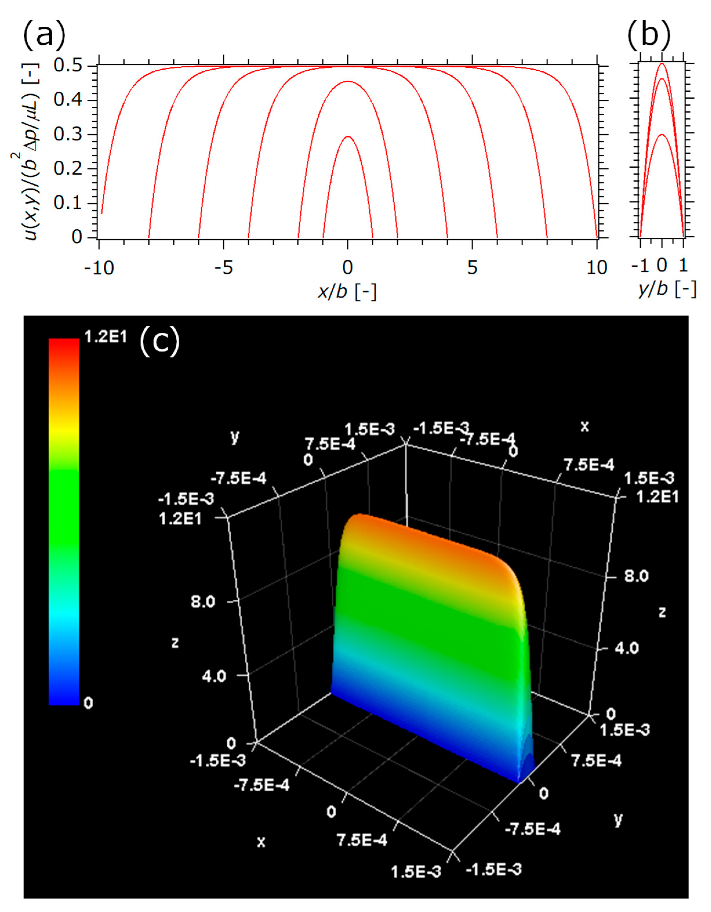
2.2. CFD Simulation
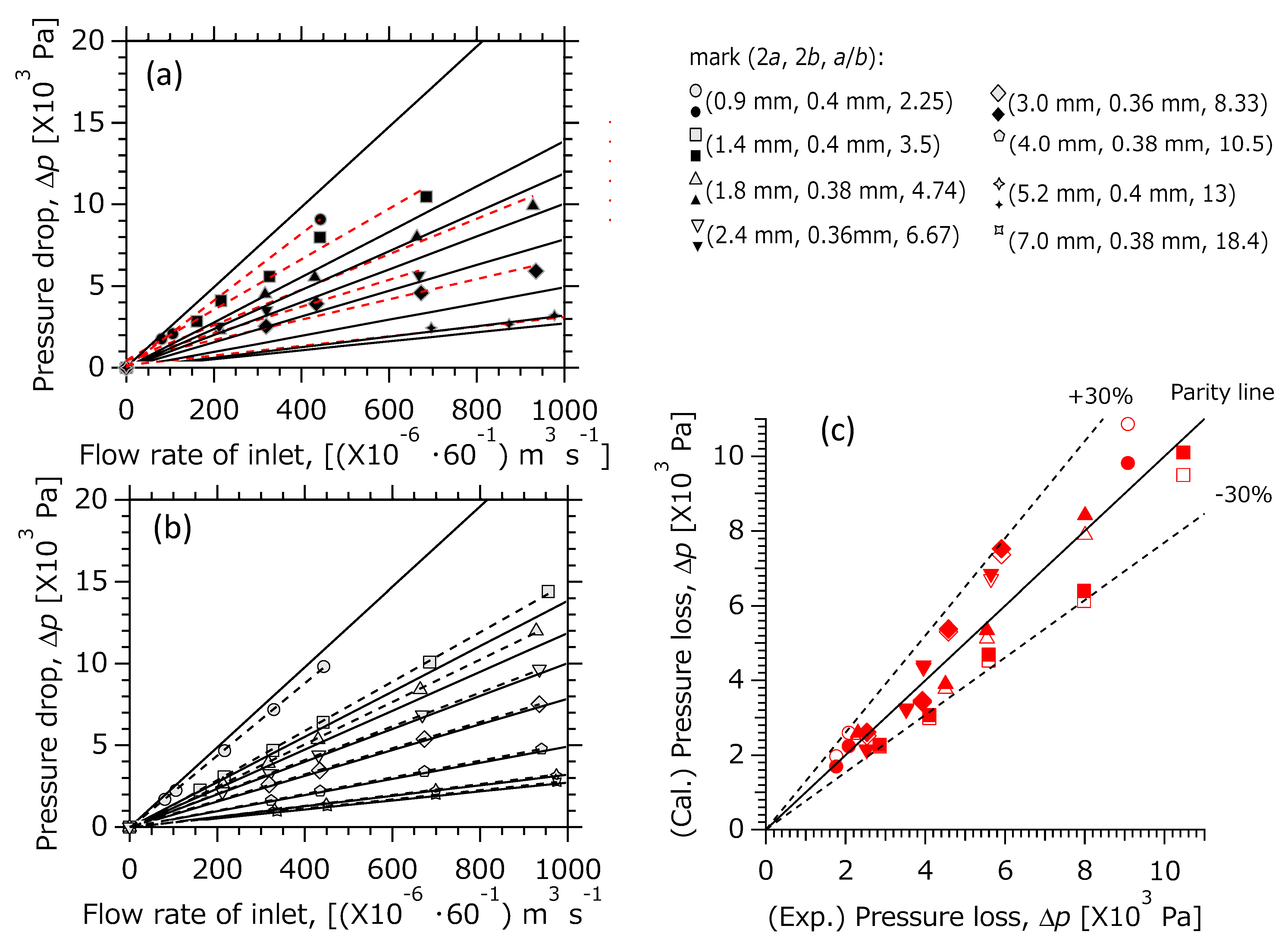
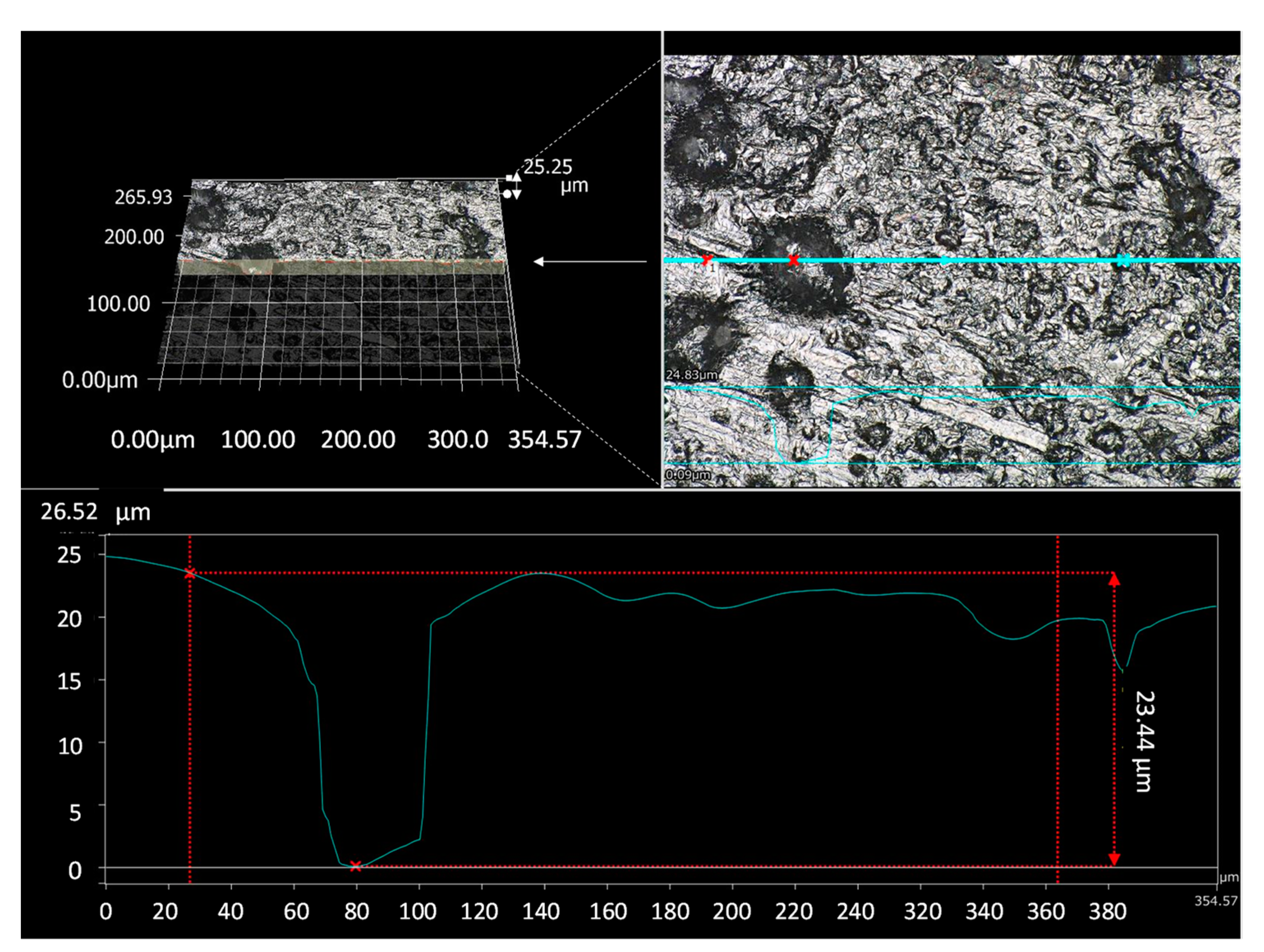
2.3. Experimental
3. Results and Discussion
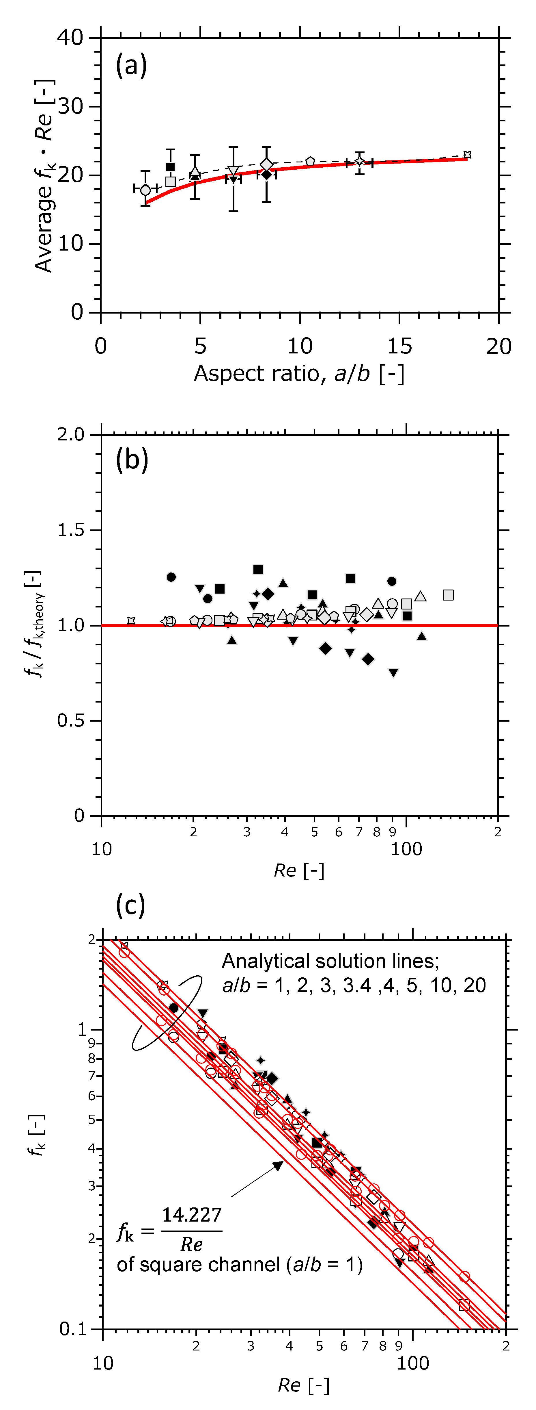
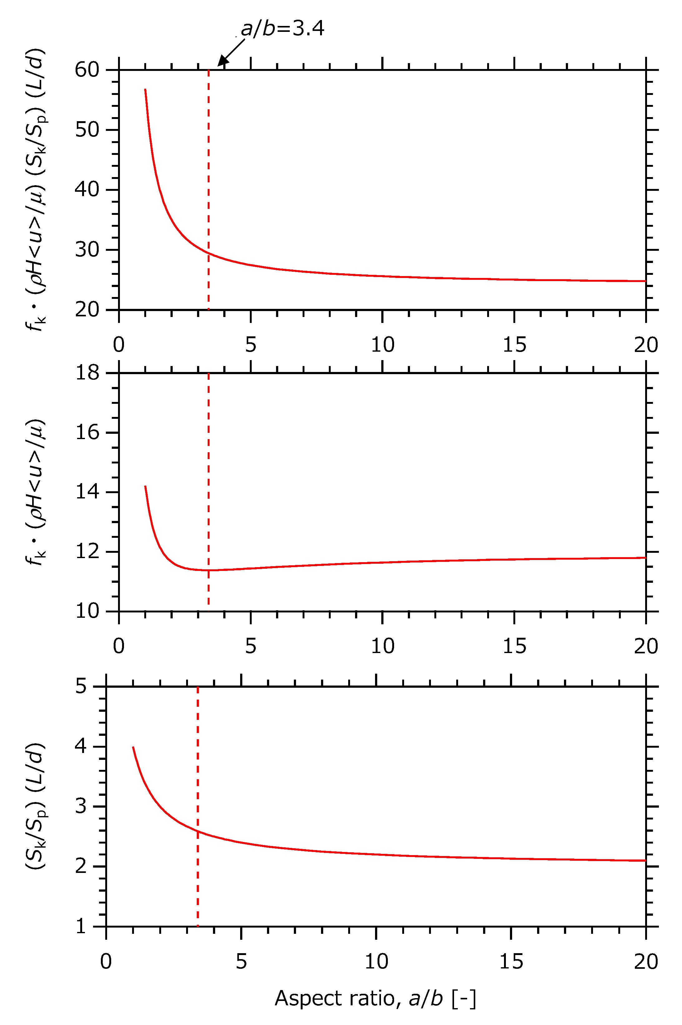
3.1. Analysis of the Theoretical Equations
3.2. Comparison between the Analitical Solution and the Results of the Detailed Systems
4. Summary
Author Contributions
Funding
Data Availability Statement
Conflicts of Interest
Abbreviations
| CFD | computational fluid dynamics |
| 1D | one-dimensional |
| 3D | three-dimensional |
Nomenclature
| Alphabets | ||
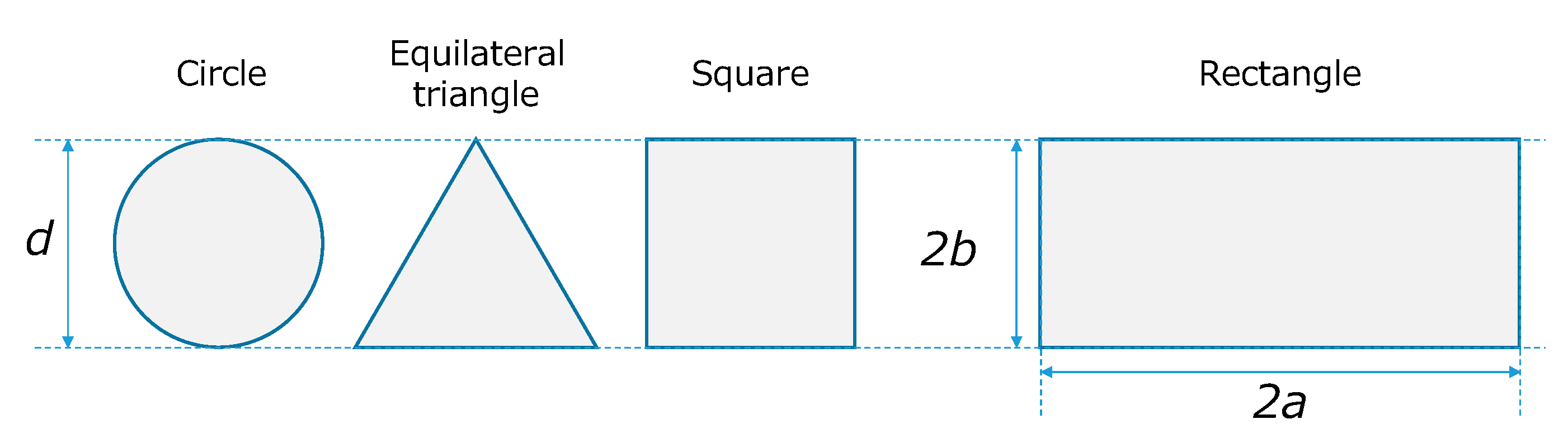
| a | half the length in the long axis direction of cross-sectional rectangle | [m] |
| b | half the length in the short axis direction of cross-sectional rectangle | [m] |
| d | flow path height | [m] |
| dH | hydraulic diameter | [m] |
| dp | particle size | [m] |
| fk | the Fanning friction factor | [-] |
| the Darcy friction factor | [-] | |
| Fk | fluid force | [N] |
| K | constant defined by Equation (6) | [-] |
| I | unit matrix | [-] |
| L | channel length from inlet to outlet | [m] |
| p | pressure | [Pa] |
| pressure drop | [Pa] | |
| the Reynolds number | [-] | |
| surface area between the fluid and inner wall | [m2] | |
| channel’s cross-sectional area | [m2] | |
| average flow velocity | [m·s−1] | |
| u | vector of flow velocity | [m·s−1] |
| x | coordinate along long side direction of channel’s cross-section | [m] |
| y | coordinate along short side direction of channel’s cross-section | [m] |
| z | coordinate along flow direction in channel | [m] |
| Greek letters | ||
| density of fluid | [kg·m−3] | |
| shear stress subjected to channel wall | [Pa] | |
| μ | viscosity of fluid | [Pa·s] |
| absolute roughness | [m] | |
References
- Mason, B.P.; Price, K.E.; Steinbacher, J.L.; Bogdan, A.R.; McQuade, D.T. Greener Approaches to Organic Synthesis Using Microreactor Technology. Chem. Rev. 2007, 107, 2300–2318. [Google Scholar] [CrossRef]
- Hessel, V.; Kralisch, D.; Kockmann, N.; Noël, T.; Wang, Q. Novel Process Windows for Enabling, Accelerating, and Uplifting Flow Chemistry. ChemSusChem 2013, 6, 746–789. [Google Scholar] [CrossRef] [PubMed]
- Rahimi, M.; Aghel, B.; Alitabar, M.; Sepahvand, A.; Ghasempour, H.R. Optimization of biodiesel production from soybean oil in a microreactor. Energy Convers. Manag. 2014, 79, 599–605. [Google Scholar] [CrossRef]
- Murakami, S.; Ohtaki, K.; Matsumoto, S.; Inoue, T. Parallelization of Catalytic Packed-Bed Microchannels with Pressure-Drop Microstructures for Gas–Liquid Multiphase Reactions. Jpn. J. Appl. Phys. 2012, 51, 06FK11. [Google Scholar] [CrossRef]
- Mei, D.; Lou, X.; Qian, M.; Yao, Z.; Liang, L.; Chen, Z. Effect of tip clearance on the heat transfer and pressure drop performance in the micro-reactor with micro-pin–fin arrays at low Reynolds number. Int. J. Heat Mass Transfer 2015, 70, 709–718. [Google Scholar] [CrossRef]
- Tourvieille, J.N.; Philippe, R.; de Bellefon, C. Milli-channel with metal foams under an applied gas–liquid periodic flow: External mass transfer performance and pressure drop. Chem. Eng. J. 2015, 267, 332–346. [Google Scholar] [CrossRef]
- Tsubogo, T.; Oyamada, H.; Kobayashi, S. Multistep continuous-flow synthesis of (R)- and (S)-rolipram using heterogeneous catalysts. Nature 2015, 520, 329–332. [Google Scholar] [CrossRef] [PubMed]
- Adamo, A.; Beingessner, R.L.; Behnam, M.; Chen, J.; Jamison, T.F.; Jensen, K.F.; Monbaliuallan, J.-C.M.; Myerson, A.S.; Revalor, E.M.; Snead, D.R.; et al. On-demand continuous-flow production of pharmaceuticals in a compact, reconfigurable system. Science 2016, 352, 61–67. [Google Scholar] [CrossRef] [PubMed] [Green Version]
- Jensen, K.F. Flow chemistry—Microreaction technology comes of age. AIChE J. 2017, 63, 858–869. [Google Scholar] [CrossRef]
- Hasebe, S. Design and operation of micro-chemical plants—Bridging the gap between nano, micro and macro technologies. Comput. Chem. Eng. 2004, 29, 57–64. [Google Scholar] [CrossRef]
- Schenk, R.; Hessel, V.; Hofmann, C.; Kiss, J.; Löwe, H.; Ziogas, A. Numbering-up of micro devices: A first liquid-flow splitting unit. Chem. Eng. J. 2004, 101, 421–429. [Google Scholar] [CrossRef]
- Saber, M.; Commenge, J.M.; Falk, L. Microreactor numbering-up in multi-scale networks for industrial-scale applications: Impact of flow maldistribution on the reactor performances. Chem. Eng. Sci. 2010, 65, 372–379. [Google Scholar] [CrossRef]
- Engelbrecht, N.; Everson, C.R.; Bessarabov, D.; Kolb, G. Microchannel reactor heat-exchangers: A review of design strategies for the effective thermal coupling of gas phase reactions. Chem. Eng. Process.—Process Intensif. 2020, 157, 108164. [Google Scholar] [CrossRef]
- Görke, O.; Pfeifer, P.; Schubert, K. Highly selective methanation by the use of a microchannel reactor. Catal. Today 2005, 110, 132–139. [Google Scholar] [CrossRef]
- Lerou, J.J.; Tonkovich, A.L.; Silva, L.; Perry, S.; McDaniel, J. Microchannel reactor architecture enables greener processes. Chem. Eng. Sci. 2010, 65, 380–385. [Google Scholar] [CrossRef]
- Fukuda, T.; Kawanami, H.; Miyazawa, A. Development of a Newly Catalytic Plate-type Reactor and Its Evaluation of Methane Conversion and Pressure Drop in Dry Reforming of Methane. J. Chem. Eng. Jpn. 2017, 50, 657–665. [Google Scholar] [CrossRef] [Green Version]
- Fukuda, T.; Harada, M.R.; Hamzah, A.B.; Ookawara, S.; Yoshikawa, S.; Matsumoto, H. Double-layered catalytic wall-plate microreactor for process intensification of dry reforming of methane: Reaction activity improvement and coking suppression. Chem. Eng. Process.—Process Intensif. 2021, 164, 108406. [Google Scholar] [CrossRef]
- Hamzah, A.B.; Fukuda, T.; Ookawara, S.; Yoshikawa, S.; Matsumoto, H. Process intensification of dry reforming of methane by structured catalytic wall-plate microreactor. Chem. Eng. J. 2021, 412, 128636. [Google Scholar] [CrossRef]
- Fukuda, T.; Maki, T.; Mae, K. Design of a Plate-Type Catalytic Microreactor with CO2 Permeation Membrane for Water-Gas Shift Reaction. Chem. Eng. Technol. 2012, 35, 1205–1213. [Google Scholar] [CrossRef]
- Tullius, J.F.; Tullius, T.K.; Bayazitoglu, Y. Optimization of short micro pin fins in minichannels. Int. J. Heat Mass Transfer 2012, 55, 3921–3932. [Google Scholar] [CrossRef]
- Yao, X.; Zhang, Y.; Du, L.; Liu, J.; Yao, J. Review of the applications of microreactors. Renew. Sustain. Energy Rev. 2015, 47, 519–539. [Google Scholar] [CrossRef]
- Fukuda, T.; Sawada, M.; Maki, T.; Mae, K. Basic Design Concept of a Microreactor for Isothermal Operation Including Heat Conductivity. Chem. Eng. Technol. 2013, 36, 968–974. [Google Scholar] [CrossRef]
- Fukuda, T.; Harada, R.M.; Miyazawa, A. Influence of channel dimensions and operational parameters on methane dry-reforming reaction in a catalytic wall-plate reactor and its design methodology. React. Chem. Eng. 2019, 4, 537–549. [Google Scholar] [CrossRef]
- Peiyi, W.; Little, W.A. Measurement of friction factors for the flow of gases in very fine channels used for microminiature Joule-Thomson refrigerators. Cryogenics 1983, 23, 273–277. [Google Scholar] [CrossRef]
- Pfahler, J.; Harley, J.; Bau, H.; Zemel, J. Liquid transport in micron and submicron channels. Sens. Actuators A Phys. 1990, 22, 431–434. [Google Scholar] [CrossRef]
- Peng, X.F.; Peterson, G.P.; Wang, B.X. Frictional flow characteristics of water flowing through rectangular microchannels. Exp. Heat Transfer 1994, 7, 249–264. [Google Scholar] [CrossRef]
- Wilding, P.; Shoffner, M.A.; Kircka, L.J. PCR in a silicon microstructure. Clin. Chem. 1994, 40, 1815–1818. [Google Scholar] [CrossRef]
- Jiang, X.N.; Zhou, J.Y.; Yao, Y.L.; Ye, X.Y. Micro-fluid Flow In Microchannel. Proc. Transducers. 1995, 95, 317–320. [Google Scholar] [CrossRef]
- Hetsroni, G.; Mosyak, A.; Pogrebnyak, E.; Yarin, L.P. Fluid Flow in Micro-Channels. Int. J. Heat Mass Transfer 2005, 48, 1982–1998. [Google Scholar] [CrossRef]
- Kohl, M.J.; Abdel-Khalik, S.I.; Jeter, S.M.; Sadowski, D.L. An experimental investigation of microchannel flow with internal pressure measurements. Int. J. Heat Mass Transfer 2005, 48, 1518–1533. [Google Scholar] [CrossRef]
- Nagamoto, H.; Kobayashi, Y.; Otomo, J.; Oshima, E. Laminar Flow Characteristics in a Rectangular Microchannel. Kagaku kogaku Ronbunshu 2006, 32, 293–296. (In Japanese) [Google Scholar] [CrossRef]
- Pashchenko, D. Effect of the geometric dimensionality of computational domain on the results of CFD-modeling of steam methane reforming. Int. J. Hydrogen Energy 2018, 43, 8662–8673. [Google Scholar] [CrossRef]
- Müller, W. Einführung in Die Theorie der Zähen Flüssigkeiten; (Nenseiryuutai no Rikigaku) (Translation); Korona-Sha: Tokyo, Japan, 1942; 82p. [Google Scholar]
- Fukuda, T.; Harada, M.R.; Miyazawa, A. Heat exchangeability of a catalytic plate reactor and analysis of the reactivity of steam and CO2 in methane reforming. Chem. Eng. Technol. 2019, 42, 2127–2137. [Google Scholar] [CrossRef] [Green Version]
- Moody, L.F. Friction factors for pipe flow. Trans. ASME 1944, 66, 671–684. [Google Scholar]
- Harley, J.; Huang, Y.; Bau, H.; Zemel, J. Gas flow in micro-channels. J. Fluid Mech. 1995, 284, 257–274. [Google Scholar] [CrossRef]


| Sk | Sp | dH | fk | Re | |||
|---|---|---|---|---|---|---|---|
| Circle | |||||||
| Equilateral triangle | |||||||
| Square | |||||||
| Rectangle |
Publisher’s Note: MDPI stays neutral with regard to jurisdictional claims in published maps and institutional affiliations. |
© 2021 by the authors. Licensee MDPI, Basel, Switzerland. This article is an open access article distributed under the terms and conditions of the Creative Commons Attribution (CC BY) license (https://creativecommons.org/licenses/by/4.0/).
Share and Cite
Fukuda, T.; Harada, M.R. Analysis of Aspect Ratio in a Miniature Rectangle Channel for Low Frictional Resistance. Micromachines 2021, 12, 1580. https://doi.org/10.3390/mi12121580
Fukuda T, Harada MR. Analysis of Aspect Ratio in a Miniature Rectangle Channel for Low Frictional Resistance. Micromachines. 2021; 12(12):1580. https://doi.org/10.3390/mi12121580
Chicago/Turabian StyleFukuda, Takashi, and Makoto Ryo Harada. 2021. "Analysis of Aspect Ratio in a Miniature Rectangle Channel for Low Frictional Resistance" Micromachines 12, no. 12: 1580. https://doi.org/10.3390/mi12121580
APA StyleFukuda, T., & Harada, M. R. (2021). Analysis of Aspect Ratio in a Miniature Rectangle Channel for Low Frictional Resistance. Micromachines, 12(12), 1580. https://doi.org/10.3390/mi12121580