
Surface Integrity and Friction Performance of Brass H62 Textured by One-Dimensional Ultrasonic Vibration-Assisted Turning


Abstract
:1. Introduction
2. Sample Preparation
3. Surface Topography
4. Subsurface Microstructure
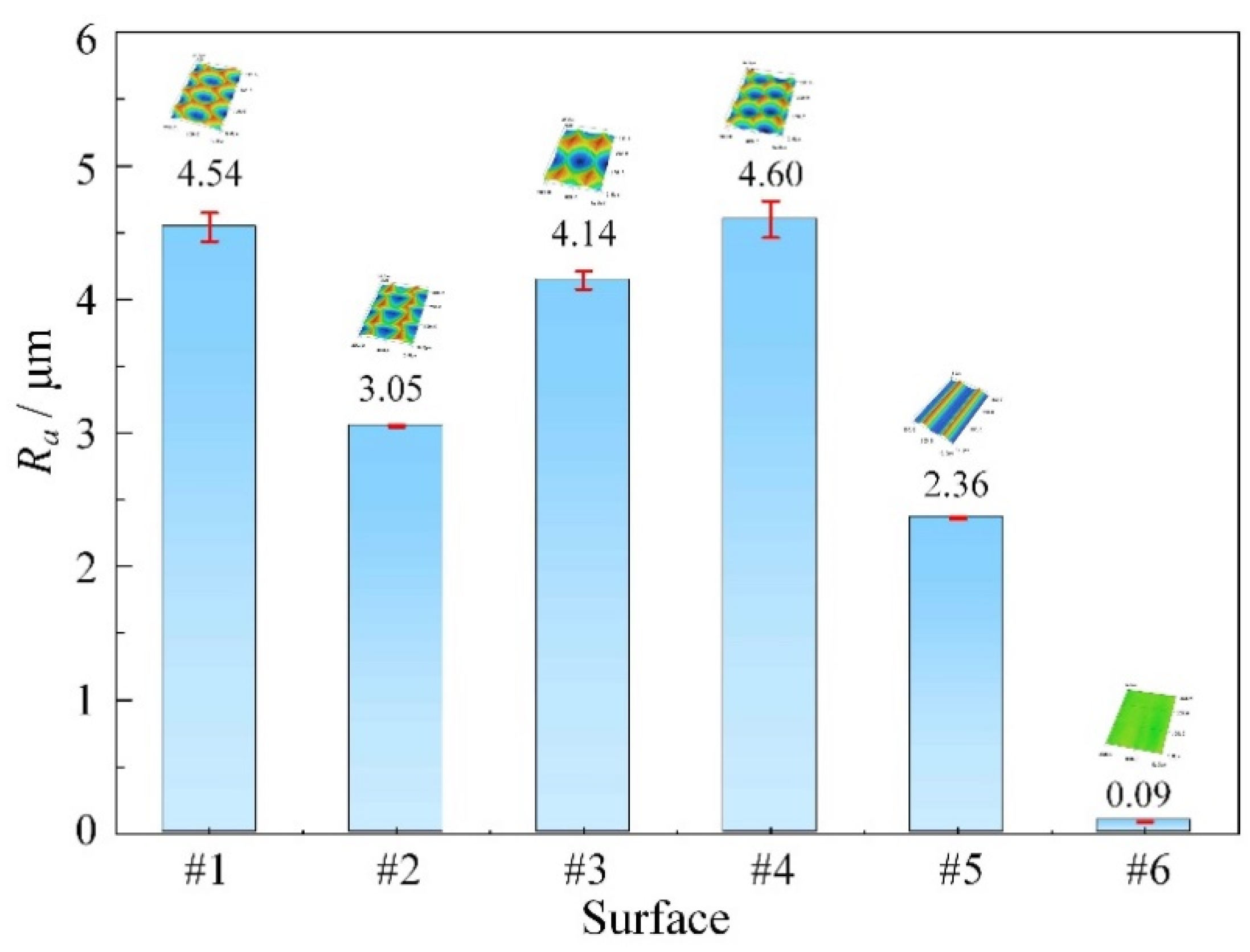
5. Surface Roughness
6. Friction Performance
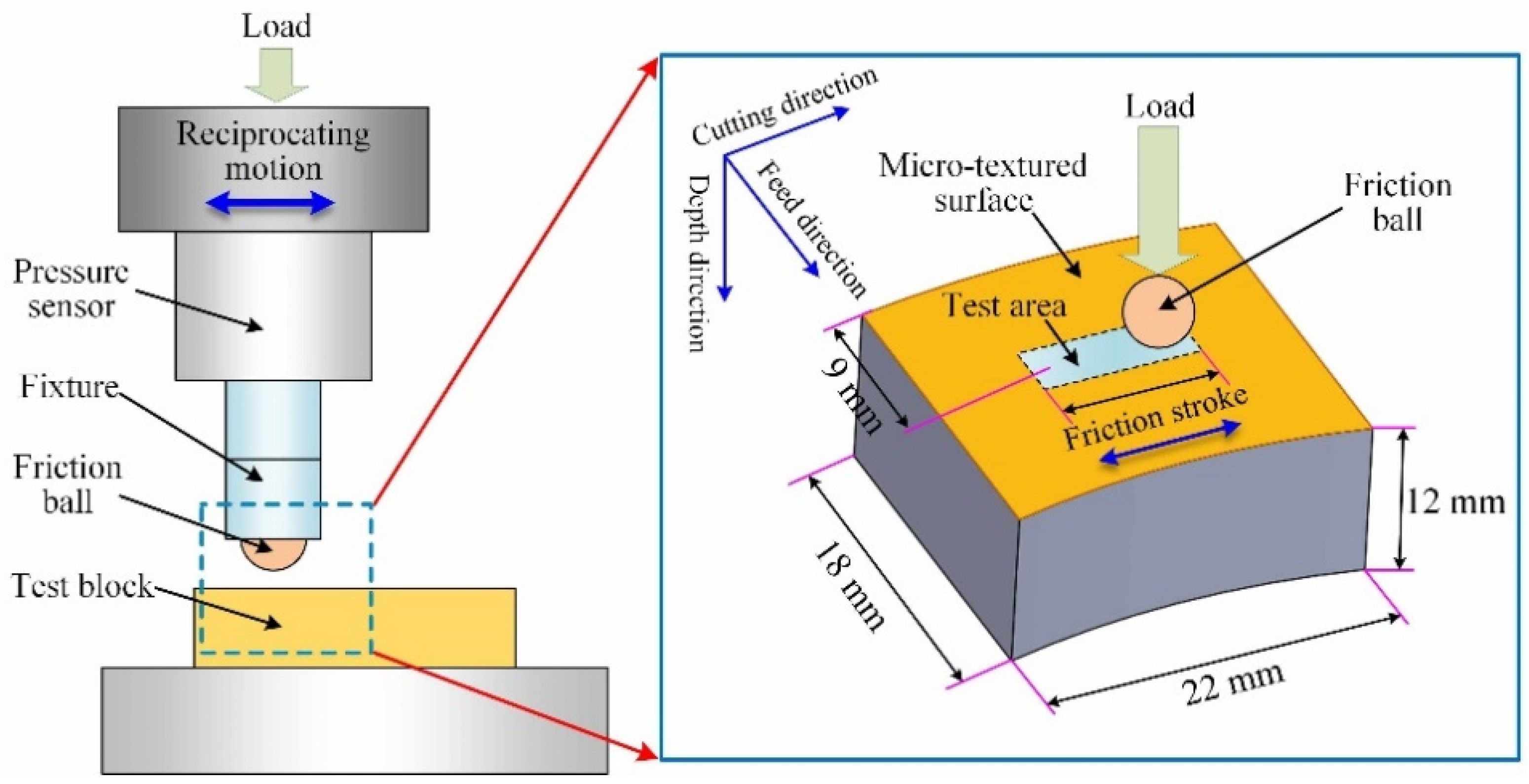
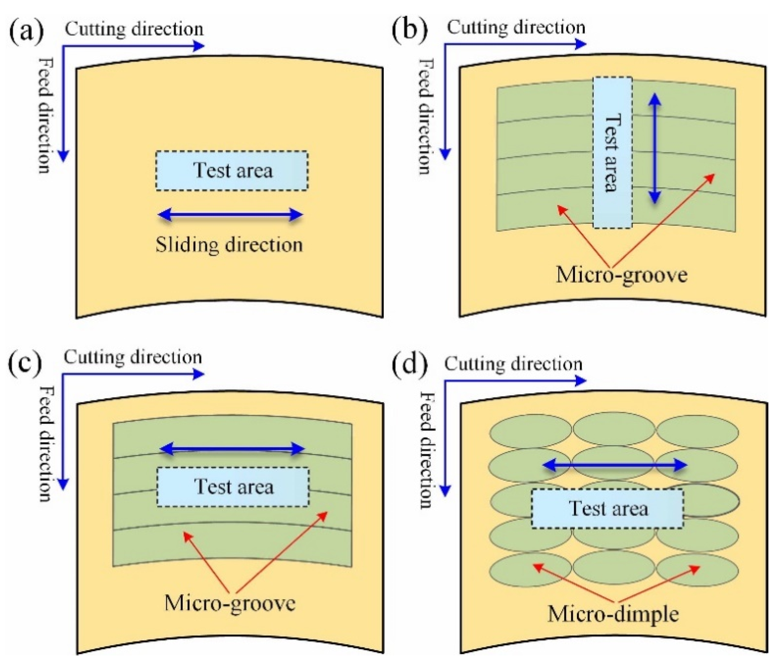
6.1. Test Procedure
6.2. Results and Discussion
7. Conclusions
- (1)
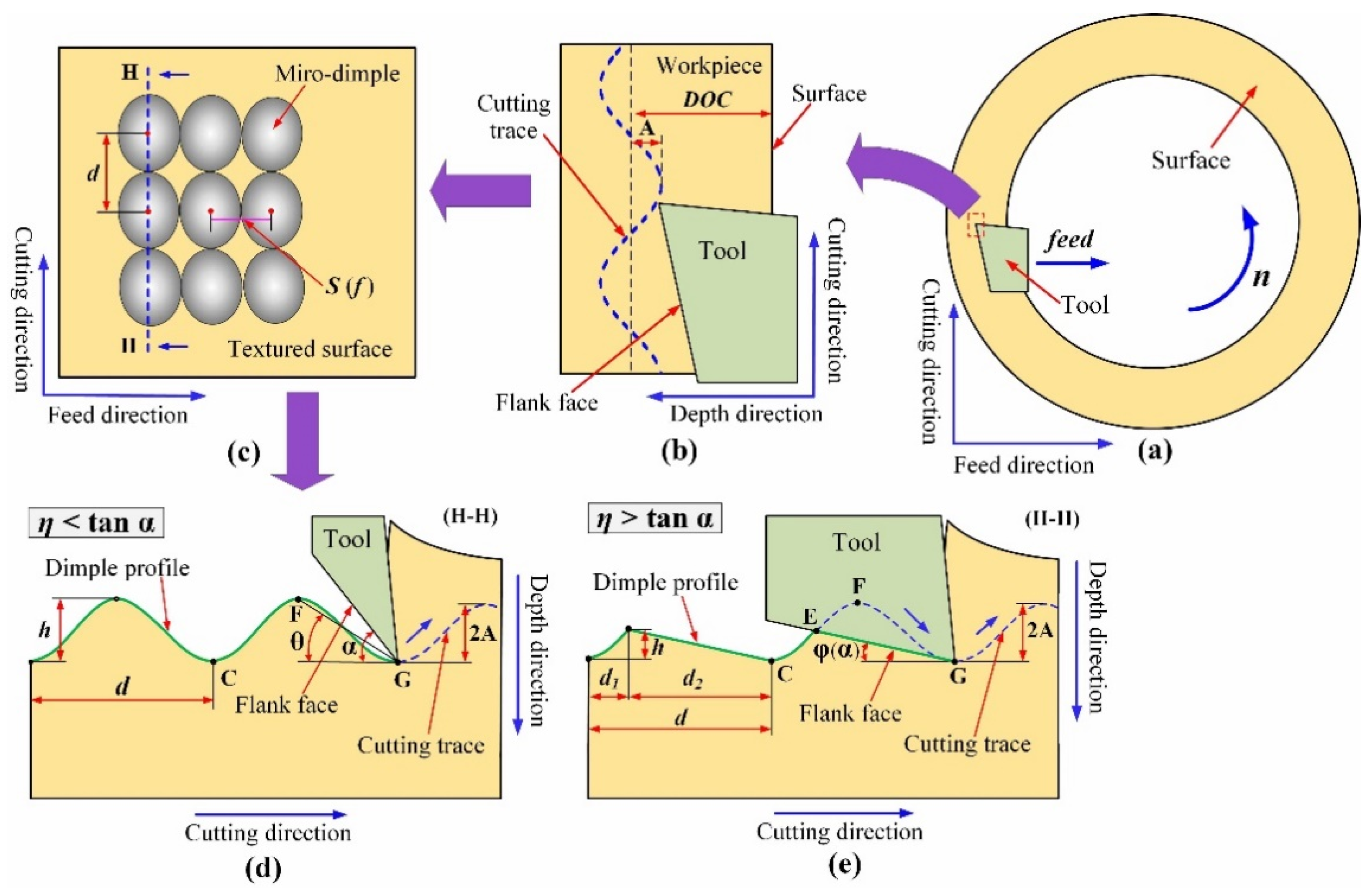
- By observing the inclination of grain boundary, it is confirmed that when the ultrasonic vibration is applied to the depth direction of turning, the elastoplastic deformation of the subsurface becomes larger, and the intersection state between the flank face and cutting trace has an important effect on the deformation degree. This provides a valid proof to further reveal the reason for the deviation between the theoretical and experimental values of dimple depth.
- (2)
- Compared with the micro-grooved surface fabricated by the turning without ultrasonic vibration, the micro-textured surface generated by 1D UVAT has greater surface roughness. The surface roughness value is related to the number of micro-dimples per unit area and dimple size.
- (3)
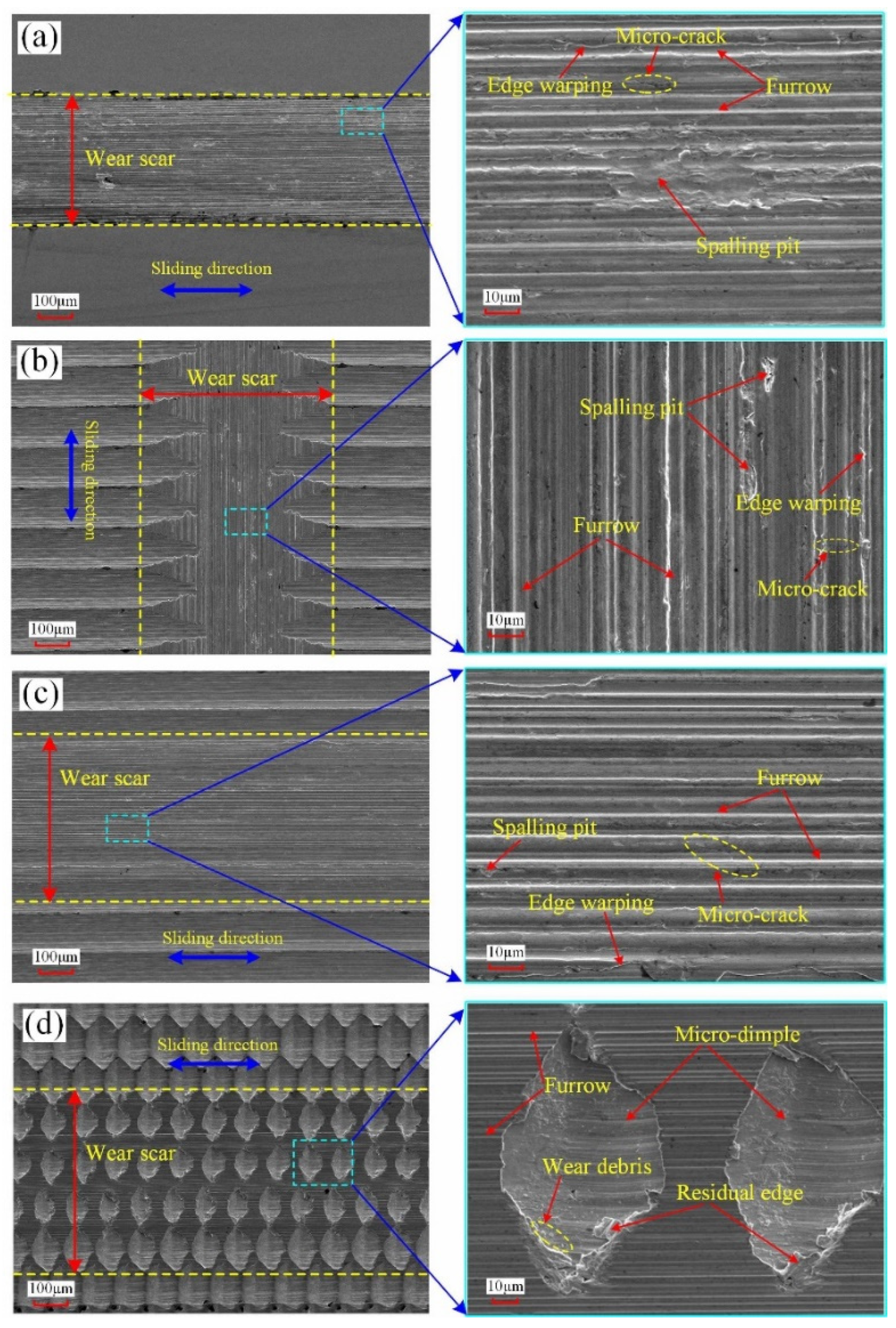
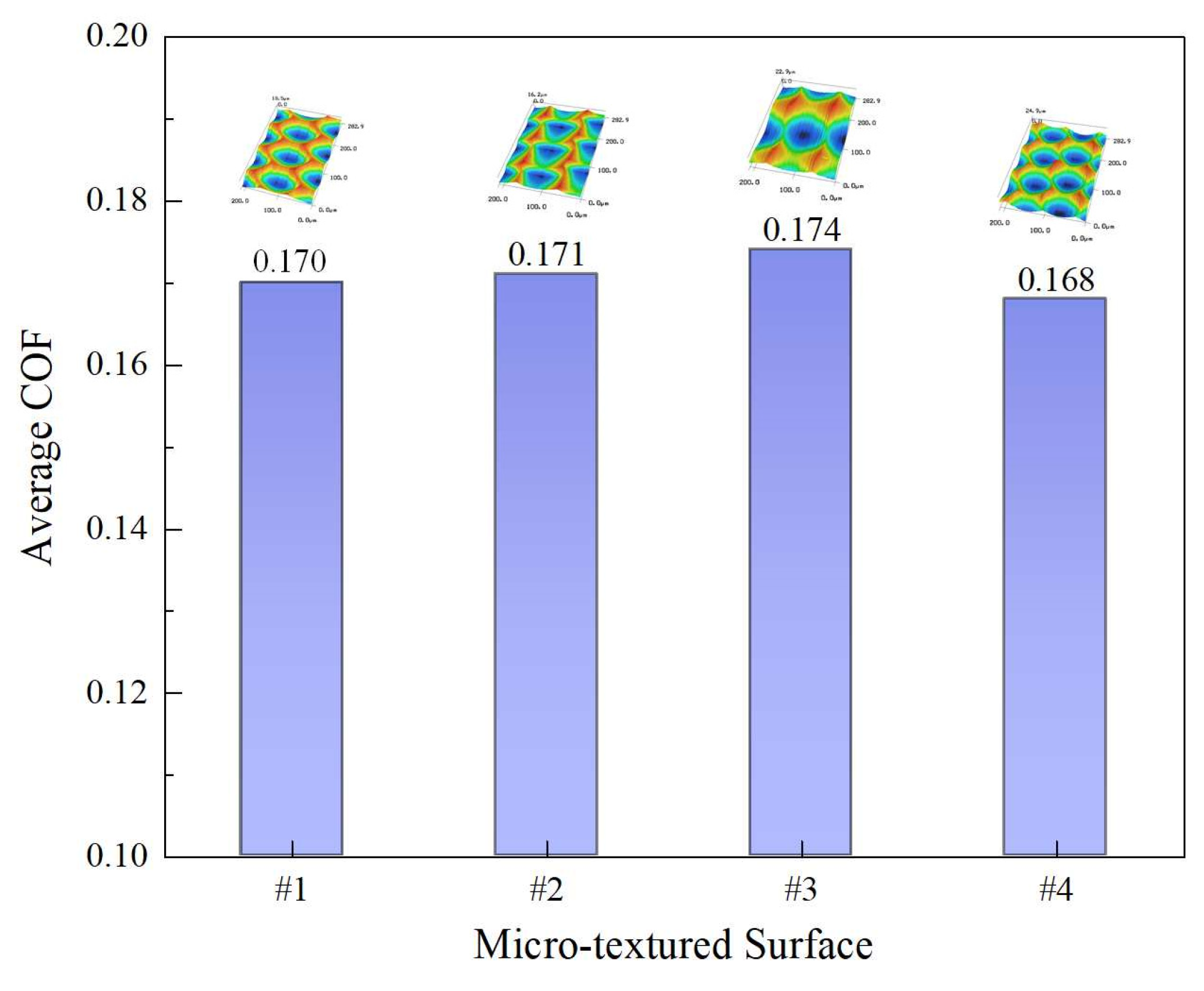
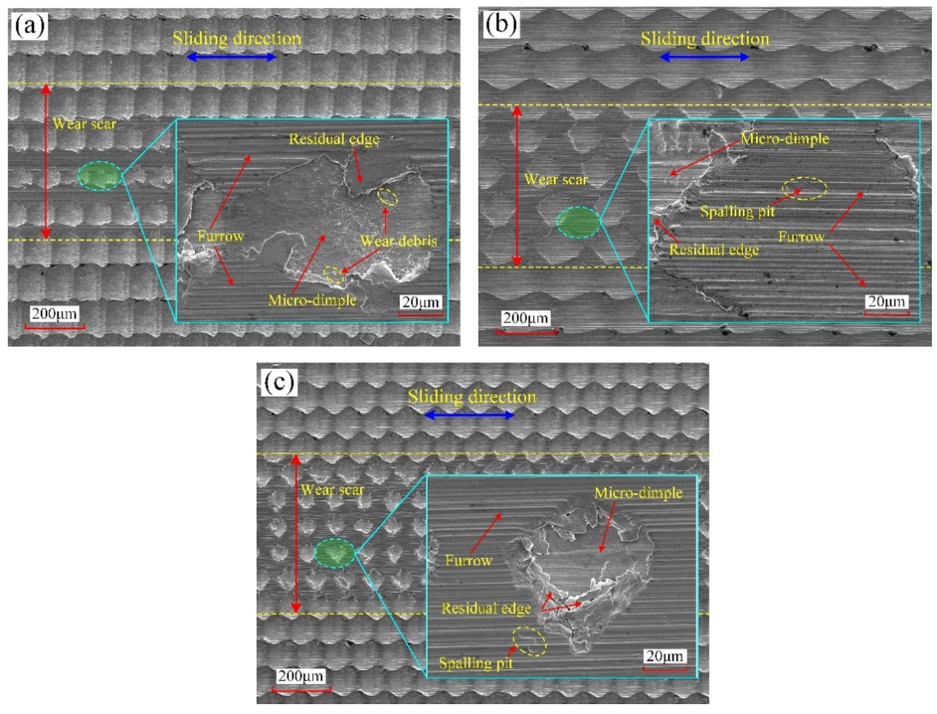
- Under the oil lubricating conditions of low speed and light load, the micro-dimpled surfaces fabricated by the 1D UVAT have better friction performance than the micro-grooved surface and the polished surface. Compared with the micro-grooved surface and polished surface, the average COF in the stable stage of the micro-dimpled surface can be reduced by up to 33.1%. The continuous micro-dimples mainly play the role of oil storage and debris containment in this linear reciprocating sliding process, which can provide enough lubricating oil for the tribo-surface and reduce the wear degree of the surface materials caused by abrasive. The number of micro-dimples per unit area has a great effect on the friction performance. Choosing the surface with a greater number of continuous micro-dimples per unit area is beneficial to improve the surface friction performance. As a consequence, this study proves that the proposed surface texturing method, 1D UVAT, can be a feasible candidate for the fabrication of micro-textured surfaces with better tribological property, which also lays a certain foundation for the further application of this surface texturing.
Author Contributions
Funding
Acknowledgments
Conflicts of Interest
References
- Bruzzone, A.A.G.; Costa, H.L.; Lonardo, P.M.; Lucca, D.A. Advances in engineered surfaces for functional performance. CIRP Ann. 2008, 57, 750–769. [Google Scholar] [CrossRef]
- Gropper, D.; Wang, L.; Harvey, T.J. Hydrodynamic lubrication of textured surfaces: A review of modeling techniques and key findings. Tribol. Int. 2016, 94, 509–529. [Google Scholar] [CrossRef] [Green Version]
- Lu, P.; Wood, R.J.K. Tribological performance of surface texturing in mechanical applications—a review. Surf. Topogr. Metrol. Prop. 2020, 8, 043001. [Google Scholar] [CrossRef]
- Sudeep, U.; Tandon, N.; Pandey, R.K. Performance of lubricated rolling/sliding concentrated contacts with surface textures: A review. J. Tribol. 2015, 137, 031501. [Google Scholar] [CrossRef]
- Tala-Ighil, N.; Maspeyrot, P.; Fillon, M.; Bounif, A. Effects of surface texture on journal-bearing characteristics under steady-state operating conditions. Proc. Inst. Mech. Eng. Part J J. Eng. Tribol. 2007, 221, 623–633. [Google Scholar] [CrossRef]
- Kligerman, Y.; Etsion, I.; Shinkarenko, A. Improving tribological performance of piston rings by partial surface texturing. J. Tribol. Trans. ASME 2005, 127, 632–638. [Google Scholar] [CrossRef]
- Yu, X.Q.; He, S.; Cai, R.L. Frictional characteristics of mechanical seals with a laser-textured seal face. J. Mater. Process. Technol. 2002, 129, 463–466. [Google Scholar] [CrossRef]
- Ramesh, A.; Akram, W.; Mishra, S.P.; Cannon, A.H.; Polycarpou, A.A.; King, W.P. Friction characteristics of microtextured surfaces under mixed and hydrodynamic lubrication. Tribol. Int. 2013, 57, 170–176. [Google Scholar] [CrossRef]
- Suh, A.Y.; Lee, S.C.; Polycarpou, A.A. Adhesion and friction evaluation of textured slider surfaces in ultra-low flying head-disk interfaces. Tribol. Lett. 2004, 17, 739–749. [Google Scholar] [CrossRef]
- Ganapathi, S.K.; Talke, F.E. Correlation between contact start/stop and constant speed drag testing in magnetic head-disk tribology. J. Tribol. Trans. ASME 1993, 115, 387–391. [Google Scholar] [CrossRef]
- Tan, A.H.; Cheng, W.S. A novel textured design for hard disk tribology improvement. Tribol. Int. 2006, 39, 506–511. [Google Scholar] [CrossRef]
- Zou, M.; Cai, L.; Wang, H. Adhesion and friction studies of a nano-textured surface produced by spin coating of colloidal silica nanoparticle solution. Tribol. Lett. 2006, 21, 25–30. [Google Scholar] [CrossRef]
- Da Silva, W.M.; Suarez, M.P.; Machado, A.R.; Costa, H.L. Effect of laser surface modification on the micro-abrasive wear resistance of coated cemented carbide tools. Wear 2013, 302, 1230–1240. [Google Scholar] [CrossRef]
- Ma, J.; Duong, N.H.; Lei, S. Numerical investigation of the performance of microbump textured cutting tool in dry machining of AISI 1045 steel. J. Manuf. Process. 2015, 19, 194–204. [Google Scholar] [CrossRef]
- Wu, Z.; Deng, J.; Su, C.; Luo, C.; Xia, D. Performance of the micro-texture self-lubricating and pulsating heat pipe self-cooling tools in dry cutting process. Int. J. Refract. Met. Hard Mat. 2014, 45, 238–248. [Google Scholar] [CrossRef]
- Zhang, K.; Deng, J.; Sun, J.; Jiang, C.; Liu, Y.; Chen, S. Effect of micro/nano-scale textures on anti-adhesive wear properties of WC/Co-based TiAlN coated tools in AISI 316 austenitic stainless steel cutting. Appl. Surf. Sci. 2015, 355, 602–614. [Google Scholar] [CrossRef]
- Nishimoto, S.; Bhushan, B. Bioinspired self-cleaning surfaces with superhydrophobicity, superoleophobicity, and superhydrophilicity. RSC Adv. 2013, 44, 671–690. [Google Scholar] [CrossRef]
- Bixler, G.D.; Bhushan, B. Bioinspired rice leaf and butterfly wing surface structures combining shark skin and lotus effects. Soft Matter 2012, 8, 11271–11284. [Google Scholar] [CrossRef]
- Chen, H.; Zhang, P.; Zhang, L.; Iu, H.; Jiang, Y.; Zhang, D.; Han, Z.; Jiang, L. Continuous directional water transport on the peristome surface of Nepenthes alata. Nature 2016, 532, 85–89. [Google Scholar] [CrossRef] [PubMed]
- Qin, L.; Hafezi, M.; Yang, H.; Dong, G.; Zhang, Y. Constructing a dual-function surface by microcasting and nanospraying for efficient drag reduction and potential antifouling capabilities. Micromachines 2019, 10, 490. [Google Scholar] [CrossRef] [Green Version]
- Fu, Y.; Yuan, C.; Bai, X.; Li, T. Study on drag reduction performance of antifouling ribbed surfaces. J. Ship Prod. Des. 2018, 34, 32–41. [Google Scholar]
- Patel, D.S.; Singh, A.; Balani, K.; Ramkumar, J. Topographical effects of laser surface texturing on various time-dependent wetting regimes in Ti6Al4V. Surf. Coat. Technol. 2018, 349, 816–829. [Google Scholar] [CrossRef]
- Pettersson, U.; Jacobson, S. Influence of surface texture on boundary lubricated sliding contacts. Tribol. Int. 2003, 36, 857–864. [Google Scholar] [CrossRef]
- Akhtar, R.R.; Yi, Q. A review on micro-manufacturing, micro-forming and their key issues. Procedia Eng. 2013, 53, 665–672. [Google Scholar]
- Zhou, R.; Cao, J.; Wang, Q.J.; Meng, F.; Zimowski, K.; Xia, Z.C. Technology effect of EDT surface texturing on tribological behavior of aluminum sheet. J. Mater. Process. Technol. 2011, 211, 1643–1649. [Google Scholar] [CrossRef]
- Wakuda, M.; Yamauchi, Y.; Kanzaki, S.; Yasuda, Y. Effect of surface texturing on friction reduction between ceramic and steel materials under lubricated sliding contact. Wear 2003, 254, 356–363. [Google Scholar] [CrossRef]
- Malek, C.K.; Saile, V. Applications of LIGA technology to precision manufacturing of high-aspect-ratio micro-components and -systems, a review. Microelectron. J. 2004, 35, 131–143. [Google Scholar] [CrossRef]
- Zhang, J.; Cui, T.; Ge, C.; Sui, Y.; Yang, H. Review of micro/nano machining by utilizing elliptical vibration cutting. Int. J. Mach. Tools Manuf. 2016, 106, 109–126. [Google Scholar] [CrossRef]
- Guo, P.; Ehmann, K.F. An analysis of the surface generation mechanics of the elliptical vibration texturing process. Int. J. Mach. Tools Manuf. 2013, 64, 85–95. [Google Scholar] [CrossRef]
- Guo, P. Development of the Elliptical Vibration Texturing Process. Ph.D. Thesis, Northwestern University, Evanston, IL, USA, 2014. [Google Scholar]
- Liu, X.; Wu, D.; Zhang, J.; Hu, X.; Cui, P. Analysis of surface texturing in radial ultrasonic vibration-assisted turning. J. Mater. Process. Technol. 2019, 267, 186–195. [Google Scholar] [CrossRef]
- Liu, X.; Zhang, J.; Hu, X.; Wu, D. Influence of tool material and geometry on micro-textured surface in radial ultrasonic vibration-assisted turning. Int. J. Mech. Sci. 2019, 152, 545–557. [Google Scholar] [CrossRef]
- Liu, X.; Hu, X.; Zhang, J.; Wu, D. Study on the fabrication of micro-textured end face in one-dimensional ultrasonic vibration-assisted turning. Int. J. Adv. Manuf. Technol. 2019, 105, 2599–2613. [Google Scholar] [CrossRef]
- Palacios, M.; Bagherifard, S.; Guagliano, M.; Fernández Pariente, I. Influence of severe shot peening on wear behaviour of an aluminium alloy. Fatigue Fract. Eng. Mater. Struct. 2014, 37, 821–829. [Google Scholar] [CrossRef]
- Ma, C.; Andani, M.T.; Qin, H.; Moghaddam, N.S.; Ibrahim, H.; Jahadakbar, A.; Amerinatanzi, A.; Ren, Z.; Zhang, H.; Doll, G.L.; et al. Improving surface finish and wear resistance of additive manufactured nickel-titanium by ultrasonic nano-crystal surface modification. J. Mater. Process. Technol. 2017, 249, 433–440. [Google Scholar] [CrossRef]


| # | Workpiece | Cutting Tool | Vibration Parameters | Cutting Parameters | |||||
|---|---|---|---|---|---|---|---|---|---|
| Material | Material | Clearance Angle (°) | Nose Radius (μm) | Ultrasonic Frequency (Hz) | Vibration Amplitude (μm) | Depth of Cut (μm) | Spindle Speed (r/min) | Feed Rate (μm/rev) | |
| 1 | H62 | PCD | 20 | 200 | 19,670 | 3.9 | 80 | 300 | 110 |
| 2 | H62 | PCD | 7 | 200 | 19,670 | 3.9 | 80 | 300 | 110 |
| 3 | H62 | PCD | 20 | 200 | 19,670 | 3.9 | 80 | 600 | 110 |
| 4 | H62 | PCD | 20 | 100 | 19,670 | 3.9 | 80 | 300 | 80 |
| 5 | H62 | PCD | 20 | 200 | 0 | 0 | 80 | 300 | 110 |
| Micro-Textured Surface | Parameters | ||
|---|---|---|---|
| h | d | S | |
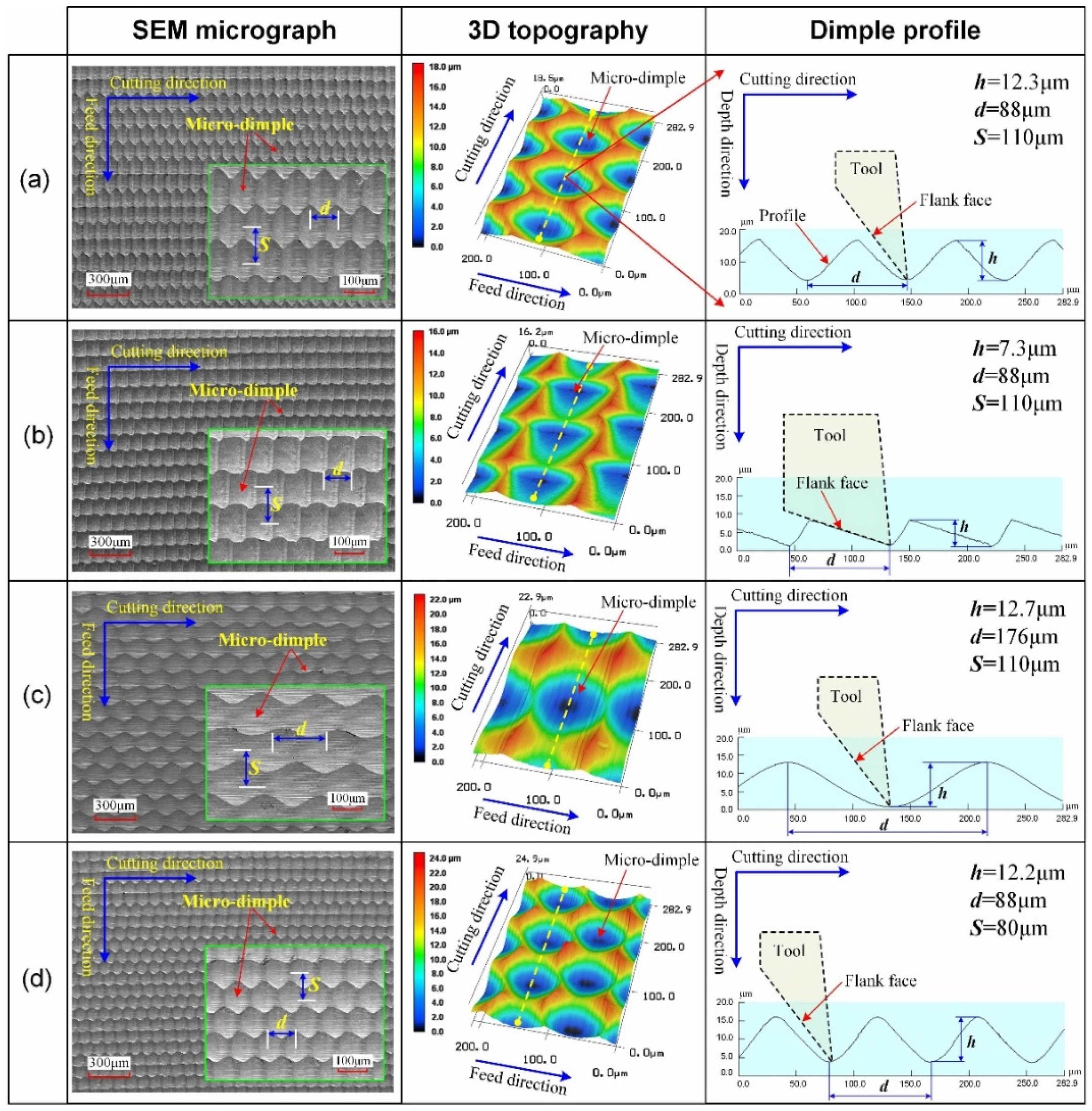
| #1 | 12.3 μm | 88 μm | 110 μm |
| #2 | 7.3 μm | 88 μm | 110 μm |
| #3 | 12.7 μm | 176 μm | 110 μm |
| #4 | 12.2 μm | 88 μm | 80 μm |
Publisher’s Note: MDPI stays neutral with regard to jurisdictional claims in published maps and institutional affiliations. |
© 2021 by the authors. Licensee MDPI, Basel, Switzerland. This article is an open access article distributed under the terms and conditions of the Creative Commons Attribution (CC BY) license (https://creativecommons.org/licenses/by/4.0/).
Share and Cite
Liu, X.; Zhang, J.; Li, L. Surface Integrity and Friction Performance of Brass H62 Textured by One-Dimensional Ultrasonic Vibration-Assisted Turning. Micromachines 2021, 12, 1398. https://doi.org/10.3390/mi12111398
Liu X, Zhang J, Li L. Surface Integrity and Friction Performance of Brass H62 Textured by One-Dimensional Ultrasonic Vibration-Assisted Turning. Micromachines. 2021; 12(11):1398. https://doi.org/10.3390/mi12111398
Chicago/Turabian StyleLiu, Xianfu, Jianhua Zhang, and Li Li. 2021. "Surface Integrity and Friction Performance of Brass H62 Textured by One-Dimensional Ultrasonic Vibration-Assisted Turning" Micromachines 12, no. 11: 1398. https://doi.org/10.3390/mi12111398
APA StyleLiu, X., Zhang, J., & Li, L. (2021). Surface Integrity and Friction Performance of Brass H62 Textured by One-Dimensional Ultrasonic Vibration-Assisted Turning. Micromachines, 12(11), 1398. https://doi.org/10.3390/mi12111398