
Controlling Resonator Nonlinearities and Modes through Geometry Optimization


Abstract
:1. Introduction
2. Materials and Methods
3. Results


4. Discussion
Author Contributions
Funding
Institutional Review Board Statement
Informed Consent Statement
Acknowledgments
Conflicts of Interest
Appendix A
Appendix B


References
- Yamagiwa, H.; Sato, S.; Fukawa, T.; Ikehara, T.; Maeda, R.; Mihara, T.; Kimura, M. Detection of Volatile Organic Compounds by Weight-Detectable Sensors coated with Metal-Organic Frameworks. Sci. Rep. 2014, 4, 6247. [Google Scholar] [CrossRef] [PubMed]
- Vyas, A.; Peroulis, D.; Bajaj, A.K. A Microresonator Design Based on Nonlinear 1 : 2 Internal Resonance in Flexural Structural Modes. J. Microelectromech. Syst. 2009, 18, 744–762. [Google Scholar] [CrossRef]
- Zhang, T.; Wei, X.; Jiang, Z.; Cui, T. Sensitivity enhancement of a resonant mass sensor based on internal resonance. Appl. Phys. Lett. 2018, 113, 223505. [Google Scholar] [CrossRef]
- Bannon, F.D.; Clark, J.R.; Nguyen, C.-C. High-Q HF microelectromechanical filters. IEEE J. Solid-State Circuits 2000, 35, 512–526. [Google Scholar] [CrossRef] [Green Version]
- Pallay, M.; Miles, R.N.; Towfighian, S. Towards a high bias voltage MEMS filter using electrostatic levitation. Mech. Syst. Signal Process. 2021, 150, 107250. [Google Scholar] [CrossRef]
- Mahboob, I.; Flurin, E.; Nishiguchi, K.; Fujiwara, A.; Yamaguchi, H. Interconnect-free parallel logic circuits in a single mechanical resonator. Nat. Commun. 2011, 2, 198. [Google Scholar] [CrossRef] [PubMed] [Green Version]
- Al Hafiz, M.A.; Kosuru, L.; Younis, M.I. Microelectromechanical reprogrammable logic device. Nat. Commun. 2016, 7, 11137. [Google Scholar] [CrossRef] [Green Version]
- Yang, W.; Towfighian, S. Internal resonance and low frequency vibration energy harvesting. Smart Mater. Struct. 2017, 26, 95008. [Google Scholar] [CrossRef]
- Du, S.; Jia, Y.; Zhao, C.; Amaratunga, G.A.J.; Seshia, A.A. A fully integrated split-electrode SSHC rectifier for piezoelectric energy harvesting. IEEE J. Solid-State Circuits 2019, 54, 1733–1743. [Google Scholar] [CrossRef]
- Antonio, D.; Zanette, D.H.; López, D. Frequency stabilization in nonlinear micromechanical oscillators. Nat. Commun. 2012, 3, 806. [Google Scholar] [CrossRef] [Green Version]
- Nguyen, C.T.-C. MEMS technology for timing and frequency control. IEEE Trans. Ultrason. Ferroelectr. Freq. Control 2007, 54, 251–270. [Google Scholar] [CrossRef] [Green Version]
- Lyshevski, S.E. MEMS and NEMS: Systems, Devices, and Structures; CRC Press: Boca Raton, FL, USA, 2018. [Google Scholar]
- Liu, Y.; Yang, J.; Liu, Z.; Cheng, Y.; Grey, F.; Zheng, Q. Mechanics and Multidisciplinary Study for Creating Graphene-Based van der Waals Nano/Microscale Devices. In IUTAM Symposium on Surface Effects in the Mechanics of Nanomaterials and Heterostructures; Springer: Berlin/Heidelberg, Germany, 2013; pp. 87–104. [Google Scholar]
- Potekin, R.; Dharmasena, S.; Keum, H.; Jiang, X.; Lee, J.; Kim, S.; Bergman, L.A.; Vakakis, A.F.; Cho, H. Multi-frequency Atomic Force Microscopy based on enhanced internal resonance of an inner-paddled cantilever. Sens. Actuators A Phys. 2018, 273, 206–220. [Google Scholar] [CrossRef]
- Westra, H.J.R.; van der Zant, H.S.J.; Venstra, W.J. Modal interactions of flexural and torsional vibrations in a microcantilever. Ultramicroscopy 2012, 120, 41–47. [Google Scholar] [CrossRef] [Green Version]
- Jeong, B.; Pettit, C.; Dharmasena, S.; Keum, H.; Lee, J.; Kim, J.; Kim, S.; McFarland, D.M.; Bergman, L.A.; Vakakis, A.F.; et al. Utilizing intentional internal resonance to achieve multi-harmonic atomic force microscopy. Nanotechnology 2016, 27, 125501. [Google Scholar] [CrossRef] [Green Version]
- Nabavi, S.; Zhang, L. Nonlinear multi-mode wideband piezoelectric mems vibration energy harvester. IEEE Sens. J. 2019, 19, 4837–4848. [Google Scholar] [CrossRef]
- Hajjaj, A.Z.; Hafiz, M.A.; Younis, M.I. Mode Coupling and Nonlinear Resonances of MEMS Arch Resonators for Bandpass Filters. Sci. Rep. 2017, 7, 41820. [Google Scholar] [CrossRef] [Green Version]
- Qalandar, K.R.; Strachan, B.S.; Gibson, B.; Sharma, M.; Ma, A.; Shaw, S.W.; Turner, K.L. Frequency division using a micromechanical resonance cascade. Appl. Phys. Lett. 2014, 105, 244103. [Google Scholar] [CrossRef] [Green Version]
- Kozinsky, I.; Postma, H.W.C.; Bargatin, I.; Roukes, M.L. Tuning nonlinearity, dynamic range, and frequency of nanomechanical resonators. Appl. Phys. Lett. 2006, 88, 253101. [Google Scholar] [CrossRef] [Green Version]
- Kacem, N.; Hentz, S. Bifurcation topology tuning of a mixed behavior in nonlinear micromechanical resonators. Appl. Phys. Lett. 2009, 95, 183104. [Google Scholar] [CrossRef]
- Hajjaj, A.Z.; Alcheikh, N.; Ramini, A.; Al Hafiz, M.A.; Younis, M.I. Highly Tunable Electrothermally and Electrostatically Actuated Resonators. J. Microelectromech. Syst. 2016, 25, 440–449. [Google Scholar] [CrossRef] [Green Version]
- Hajjaj, A.Z.; Alcheikh, N.; Younis, M.I. The static and dynamic behavior of MEMS arch resonators near veering and the impact of initial shapes. Int. J. Non-Linear Mech. 2017, 95. [Google Scholar] [CrossRef] [Green Version]
- Zhang, G.; Zhao, L.; Xu, L.; Jiang, Z.; Zhao, Y.; Wang, X.; Liu, Z. Active Frequency Tuning for Magnetically Actuated and Piezoresistively Sensed MEMS Resonators. IEEE Electron. Dev. Lett. 2013, 34, 921–923. [Google Scholar] [CrossRef]
- Cho, H.; Jeong, B.; Yu, M.-F.; Vakakis, A.F.; McFarland, D.M.; Bergman, L.A. Nonlinear hardening and softening resonances in micromechanical cantilever-nanotube systems originated from nanoscale geometric nonlinearities. Int. J. Solids Struct. 2012, 49, 2059–2065. [Google Scholar] [CrossRef] [Green Version]
- Alcheikh, N.; Ouakad, H.M.; Younis, M.I. Dynamic analysis of straight stepped microbeams. Int. J. Non-Linear Mech. 2021, 128, 103639. [Google Scholar] [CrossRef]
- Alcheikh, N.; Ouakad, H.M.; Younis, M.I. Dynamics of V-Shaped Electrothermal MEMS-Based Resonators. J. Microelectromech. Syst. 2020, 29, 1372–1381. [Google Scholar] [CrossRef]
- Dou, S.; Strachan, B.S.; Shaw, S.W.; Jensen, J.S. Structural optimization for nonlinear dynamic response. Philos. Trans. R. Soc. A Math. Phys. Eng. Sci. 2015, 373, 20140408. [Google Scholar] [CrossRef] [Green Version]
- Li, L.L.; Polunin, P.M.; Dou, S.; Shoshani, O.; Scott Strachan, B.; Jensen, J.S.; Shaw, S.W.; Turner, K.L. Tailoring the nonlinear response of MEMS resonators using shape optimization. Appl. Phys. Lett. 2017, 110, 81902. [Google Scholar] [CrossRef]
- Tripathi, A.; Bajaj, A.K. Topology optimization and internal resonances in transverse vibrations of hyperelastic plates. Int. J. Solids Struct. 2016, 81, 311–328. [Google Scholar] [CrossRef]
- Shoshani, O.; Dykman, M.I.; Shaw, S.W. Tuning linear and nonlinear characteristics of a resonator via nonlinear interaction with a secondary resonator. Nonlinear Dyn. 2020, 99, 433–443. [Google Scholar] [CrossRef]
- Tamayo, J.; Kosaka, P.M.; Ruz, J.J.; San Paulo, Á.; Calleja, M. Biosensors based on nanomechanical systems. Chem. Soc. Rev. 2013, 42, 1287–1311. [Google Scholar] [CrossRef] [Green Version]
- Raman, A.; Melcher, J.; Tung, R. Cantilever dynamics in atomic force microscopy. Nano Today 2008, 3, 20–27. [Google Scholar] [CrossRef]
- Lifshitz, R.; Cross, M.C. Nonlinear dynamics of nanomechanical and micromechanical resonators. Rev. Nonlinear Dyn. Complex. 2008, 1, 1–52. [Google Scholar]
- Asadi, K.; Yu, J.; Cho, H. Nonlinear couplings and energy transfers in micro-and nano-mechanical resonators: Intermodal coupling, internal resonance and synchronization. Philos. Trans. R. Soc. A Math. Phys. Eng. Sci. 2018, 376, 20170141. [Google Scholar] [CrossRef]
- Hajjaj, A.Z.; Jaber, N.; Ilyas, S.; Alfosail, F.K.; Younis, M.I. Linear and nonlinear dynamics of micro and nano-resonators: Review of recent advances. Int. J. Non-Linear Mech. 2019, 119, 103328. [Google Scholar] [CrossRef]
- Nitzan, S.H.; Zega, V.; Li, M.; Ahn, C.H.; Corigliano, A.; Kenny, T.W.; Horsley, D.A. Self-induced parametric amplification arising from nonlinear elastic coupling in a micromechanical resonating disk gyroscope. Sci. Rep. 2015, 5, 9036. [Google Scholar] [CrossRef] [Green Version]
- Zhou, X.; Zhao, C.; Xiao, D.; Sun, J.; Sobreviela, G.; Gerrard, D.D.; Chen, Y.; Flader, I.; Kenny, T.W.; Wu, X.; et al. Dynamic modulation of modal coupling in microelectromechanical gyroscopic ring resonators. Nat. Commun. 2019, 10, 4980. [Google Scholar] [CrossRef] [Green Version]
- Alneamy, A.M.; Khater, M.E.; Abdel-Aziz, A.K.; Heppler, G.R.; Abdel-Rahman, E.M. Electrostatic arch micro-tweezers. Int. J. Non-Linear Mech. 2020, 118, 103298. [Google Scholar] [CrossRef]
- Tajaddodianfar, F.; Pishkenari, H.N.; Yazdi, M.R.H.; Miandoab, E.M. Size-dependent bistability of an electrostatically actuated arch NEMS based on strain gradient theory. J. Phys. D Appl. Phys. 2015, 48, 245503. [Google Scholar] [CrossRef]
- Alcheikh, N.; Ramini, A.; Hafiz MAAl Younis, M.I. Tunable clamped–guided arch resonators using electrostatically induced axial loads. Micromachines 2017, 8, 14. [Google Scholar] [CrossRef] [Green Version]
- Wang, D.F.; Chatani, K.; Ikehara, T.; Maeda, R. Mode localization analysis and characterization in a 5-beam array of coupled nearly identical micromechanical resonators for ultra-sensitive mass detection and analyte identification. Microsyst. Technol. 2012, 18, 1923–1929. [Google Scholar] [CrossRef]
- Erbes, A.; Thiruvenkatanathan, P.; Woodhouse, J.; Seshia, A.A. Numerical study of the impact of vibration localization on the motional resistance of weakly coupled MEMS resonators. J. Microelectromech. Syst. 2014, 24, 997–1005. [Google Scholar] [CrossRef]
- Hajjaj, A.Z.; Alfosail, F.K.; Jaber, N.; Ilyas, S.; Younis, M.I. Theoretical and experimental investigations of the crossover phenomenon in micromachined arch resonator: Part II—simultaneous 1:1 and 2:1 internal resonances. Nonlinear Dyn. 2019, 99, 407–432. [Google Scholar] [CrossRef]
- Hajjaj, A.Z.; Jaber, N.; Hafiz, M.A.A.; Ilyas, S.; Younis, M.I. Multiple internal resonances in MEMS arch resonators. Phys. Lett. A 2018, 382, 3393–3398. [Google Scholar] [CrossRef]
- Xia, C.; Wang, D.F.; Ono, T.; Itoh, T.; Maeda, R. A mass multi-warning scheme based on one-to-three internal resonance. Mech. Syst. Signal Process. 2020, 142, 106784. [Google Scholar] [CrossRef]
- Hacker, E.; Gottlieb, O. Internal resonance based sensing in non-contact atomic force microscopy. Appl. Phys. Lett. 2012, 101, 53106. [Google Scholar] [CrossRef]
- Pu, D.; Wei, X.; Xu, L.; Jiang, Z.; Huan, R. Synchronization of electrically coupled micromechanical oscillators with a frequency ratio of 3: 1. Appl. Phys. Lett. 2018, 112, 13503. [Google Scholar] [CrossRef]
- Ouakad, H.M.; Younis, M.I. The dynamic behavior of MEMS arch resonators actuated electrically. Int. J. Non-Linear Mech. 2010, 45, 704–713. [Google Scholar] [CrossRef]
- Hajjaj, A.Z.; Jaber, N.; Alcheikh, N.; Younis, M.I. A Resonant Gas Sensor Based on Multimode Excitation of a Buckled Microbeam. IEEE Sens. J. 2019, 20, 1778–1785. [Google Scholar] [CrossRef]
- COMSOL. Available online: https://www.comsol.com/ (accessed on 1 September 2021).
- Qiu, J.; Lang, J.H.; Slocum, A.H.; Weber, A.C. A bulk-micromachined bistable relay with U-shaped thermal actuators. J. Microelectromech. Syst. 2005, 14, 1099–1109. [Google Scholar]


| Quantity | Values |
|---|---|
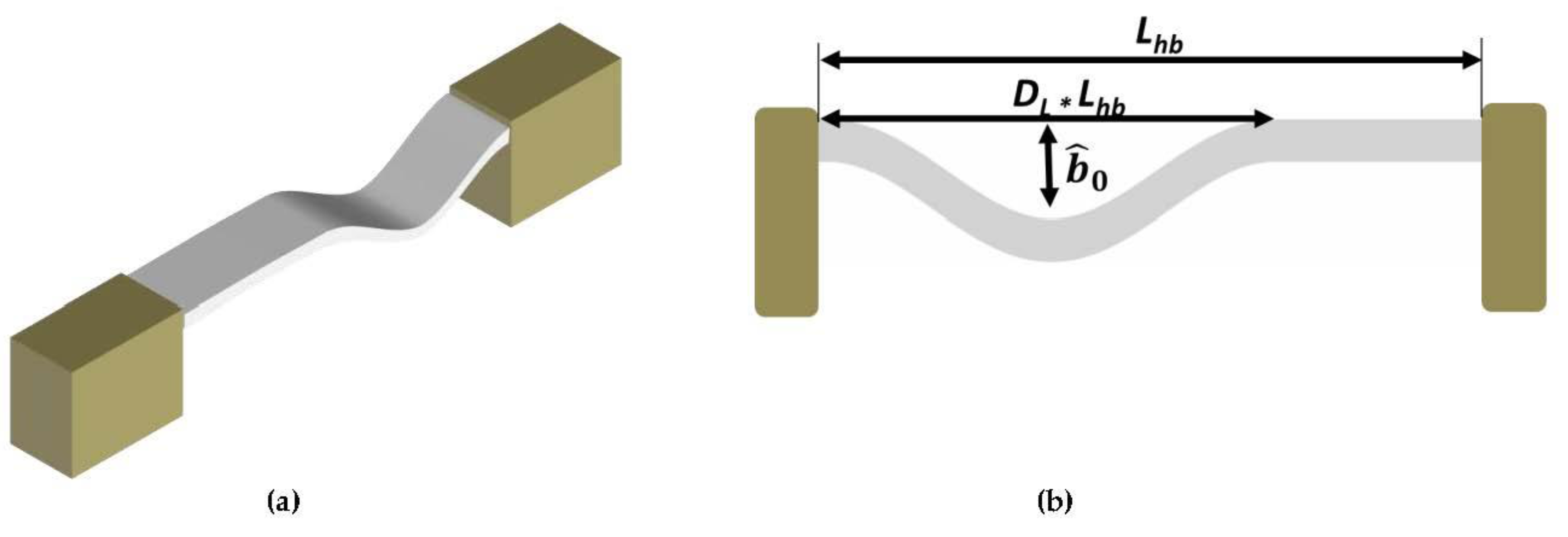
| Length, Lhb | 700 (μm) |
| Thickness, hhb | 2 (μm) |
| Width, bhb | 25 (μm) |
| Young’s Modulus, E | 169 (Gpa) |
| Density, | 2332 (kg·m−3) |
Publisher’s Note: MDPI stays neutral with regard to jurisdictional claims in published maps and institutional affiliations. |
© 2021 by the authors. Licensee MDPI, Basel, Switzerland. This article is an open access article distributed under the terms and conditions of the Creative Commons Attribution (CC BY) license (https://creativecommons.org/licenses/by/4.0/).
Share and Cite
Hajjaj, A.Z.; Jaber, N. Controlling Resonator Nonlinearities and Modes through Geometry Optimization. Micromachines 2021, 12, 1381. https://doi.org/10.3390/mi12111381
Hajjaj AZ, Jaber N. Controlling Resonator Nonlinearities and Modes through Geometry Optimization. Micromachines. 2021; 12(11):1381. https://doi.org/10.3390/mi12111381
Chicago/Turabian StyleHajjaj, Amal Z., and Nizar Jaber. 2021. "Controlling Resonator Nonlinearities and Modes through Geometry Optimization" Micromachines 12, no. 11: 1381. https://doi.org/10.3390/mi12111381
APA StyleHajjaj, A. Z., & Jaber, N. (2021). Controlling Resonator Nonlinearities and Modes through Geometry Optimization. Micromachines, 12(11), 1381. https://doi.org/10.3390/mi12111381