Article

Topological Design of Multi-Material Compliant Mechanisms with Global Stress Constraints

1
School of Mechatronics and Vehicle Engineering, East China Jiaotong University, Nanchang 330013, China
2
School of Mechanical and Mechatronic Engineering, University of Technology Sydney, Ultimo, NSW 2007, Australia
*
Authors to whom correspondence should be addressed.
Micromachines 2021, 12(11), 1379; https://doi.org/10.3390/mi12111379
Submission received: 9 October 2021 / Revised: 3 November 2021 / Accepted: 6 November 2021 / Published: 10 November 2021

Abstract

:
This paper presents an approach for the topological design of multi-material compliant mechanisms with global stress constraints. The element stacking method and the separable stress interpolation scheme are applied to calculate the element stiffness and element stress of multi-material structures. The output displacement of multi-material compliant mechanisms is maximized under the constraints of the maximum stress and the structural volume of each material. The modified P-norm method is applied to aggregate the local von Mises stress constraints for all the finite elements to a global stress constraint. The sensitivities are calculated by the adjoint method, and the method of moving asymptotes is utilized to update the optimization problem. Several numerical examples are presented to demonstrate the effectiveness of the proposed method. The appearance of the de facto hinges in the optimal mechanisms can be suppressed effectively by using the topology optimization model with global stress constraints, and the stress constraints for each material can be met.

1. Introduction

Compliant mechanisms often refer to a family of mechanisms that gain their mobility through the flexibility of some or all of its members due to the elastic body deformation [1]. Compared with the conventional rigid-body mechanisms, compliant mechanisms are featured with some unique benefits, such as easiness in fabrication, less wear and less backlash, requiring no lubrication and a built-in restoring force [2,3]. Due to these advantages and advances in advanced fabrication techniques, compliant mechanisms are already widely used in the field of precision engineering, bionic robots, intelligent structures and Micro-Electro-Mechanical Systems (MEMS) [4,5].
The methods of designing compliant mechanisms generally include two types. The first is the pseudo-rigid-body model-based method [6], which has been successfully adopted to design lumped compliant mechanisms with flexure hinges. The second is the topology optimization approach [7], which is mainly applied to design fully compliant mechanisms. Topology optimization of compliant mechanisms is a numerical process to obtain the best material distribution under a given amount of materials so that the prescribed mechanical performance can be achieved.
Ananthasuresh et al. [8] firstly introduced the homogenization method into the topological design of compliant mechanisms, which provided a new idea for designing compliant mechanisms. Thereafter, various topology optimization methods such as ground structure method [9], solid isotropic material with penalization [10,11], level set method [12,13], evolutionary structural optimization [14,15] and moving morphable components-based framework [16] were developed to design compliant mechanisms. Great progress has been gained in the topological design of compliant mechanisms. However, the topological design of compliant mechanisms is performed by using a single material in most studies. In practice, it is not always possible to use only one single material to design compliant mechanisms for achieving desired general performance. The advantages of different materials can be exploited fully to achieve comprehensive performance when multiple materials are adopted to design compliant mechanisms. It can give designers more freedom in designing advanced compliant mechanisms.
Therefore, the topological design of compliant mechanisms with multiple materials has attracted much attention. Yin et al. [17] applied a peak function material interpolation method to design multiple materials compliant mechanisms. Sigmund et al. [18] performed topological design of electrothermally driven actuators with multiple materials. Saxena et al. [19] proposed a method for the topological design of large-displacement and multi-material compliant mechanisms with multiple output ports. Wang et al. [20] used a color-level set method to design multi-material compliant mechanisms. Alonso et al. [21] used a sequential element rejection and admission method to perform topological design of multiple materials compliant mechanisms. Gaynor et al. [22] used a robust topology optimization method to design multi-material compliant mechanism. Zuo et al. [23] proposed an order multi-material isotropic material with penalization interpolation model for topological design of compliant mechanism without introducing any new variables. Wang et al. [24] applied a bi-level hierarchical optimization approach to perform topological design of compliant mechanisms with multiple materials.
Topology optimization of compliant mechanisms using no matter single material or multiple materials may be subject to de facto hinges, which usually results in stress concentration and poor fatigue performance. Great efforts have been made by many researchers to obtain hinge-free compliant mechanisms. Sigmund et al. [25] developed a class of morphology-based restriction methods to impose minimum length-scale constraints in order to eliminate the de facto hinges in the obtained compliant mechanisms. Poulsen [26] put forward a method for topological design of hinge-free compliant mechanisms by using a minimum length scale control. Yin et al. [27] used relative rotation constraints to suppress the appearance of the de facto hinges in topological design of compliant mechanisms. Zhou [28] used a hybrid discretization method to design compliant mechanisms, which can obtain hinge-free compliant mechanisms. For avoiding undesirable hinges, Luo et al. [29] developed a quadratic energy functional to control the geometric width of structural components. Wang et al. [30] put forward a method for topological design of hinge-free compliant mechanisms by using the intrinsic characteristic stiffness model. Zhu et al. [31] proposed a two-step elastic modeling method for designing compliant mechanisms, which can avoid de facto hinges.
More recently, De Leon et al. [32] adopted the stress-based topology optimization to design compliant mechanisms aiming at avoiding the appearance of the de facto hinges. Lopes et al. [33] performed topological design of compliant mechanisms with local von Mises stress constraints using the topological derivative concept, and the undesirable flexible hinges can be avoided. However, there are few studies about topology optimization of multi-material compliant mechanisms under stress constraints. Chu et al. [34] applied the stress penalty method for topology optimization design of multi-material compliant mechanism. The stress penalty term in the optimization objective is developed to control local stress constraints. Jeong et al. [35] used a separable stress interpolation scheme to solve the problem for topological design of continuum structure with multiple homogenous materials and stress constraints. Using local stress constraints, it gives rise to a topology optimization problem of multi-material compliant mechanisms with a large number of constraints. Consequently, a large computing time is required to solve the optimization problem. A large number of stress constraints can be aggregated into a global constraint by using a global stress constraints approach, and the computational efficiency can be greatly improved. However, no work has been conducted to study topological design of multiple materials compliant mechanisms using global stress constraints.
The aim of this paper is to develop a new approach for topology optimization of compliant mechanisms with multiple materials under global stress constraints. The element stacking method and the separable stress interpolation scheme are applied to calculate the element stiffness and element stress of multi-material structures, respectively. The output displacement of multi-material compliant mechanisms is maximized under the constraints of the maximum stress and the structural volume of each material. The modified P-norm method is applied to aggregate the local von Mises stress constraints for all the finite elements to a global stress constraint. The sensitivities are calculated by the adjoint method, and the method of moving asymptotes is utilized to update the topology optimization problem.
The remainder of this paper is organized as follows. In Section 2, a new optimization model for topological design of multi-material compliant mechanisms with global stress constraints is proposed. In Section 3, the sensitivity analysis of the objective and constraints are described. In Section 4, several numerical examples are used to showcase the effectiveness of the proposed method. Conclusions are given in Section 5.

2. Optimization Problem

2.1. Material Interpolation Method

Within the existing multi-material interpolation methods such as extended solid isotropic material with penalization (SIMP) [9], the Young’s modulus of the optional materials with respect to design variables are generally interpolated and assigned to a single finite element. However, only one stress value per element can be evaluated in this approach. The standard SIMP-based multi-material interpolation methods may experience difficulty in solving the problem for topological design of multi-material compliant mechanisms with stress constraints. In addition, it may be difficult to directly use the standard multi-material topology optimization approaches when multiple different materials with different Poisson’s ratios are applied to design compliant mechanisms. Unlike the standard SIMP method, more than one element is juxtaposed on the same pixel, and a finite element is selected among elements having different material properties in the element stacking method [35]. Multiple stress values per element for each material can be calculated using the separable stress interpolation scheme based on the element stacking method [36]. Therefore, the element stacking method and the separable stress interpolation scheme are used to calculate the element stiffness and element stress for multi-material compliant mechanisms, respectively.
For finite element structural analysis of multi-material topology optimization problems, the element stacking method is applied to calculate the element stiffness as
k e ( ρ ) = A i = 1 N M [ ρ e , i p 1 j = 1 j i N M [ 1 ( ρ e , j ) p 2 k e , i n ] ]
Here, k e is the element stiffness matrix, ρ denotes the element density, namely, the design variables. ρ e , i and ρ e , j represent the design variables that the i th base material and the j th base material are assigned to the e th element, respectively. k e , i n is nominal stiffness matrix of the e th element for i th base material, N M is the number of the base materials, p 1 and p 2 are the penalty exponents, which are set to 3 in this work, A i = 1 N M denotes the pixel-level assembly operator of the element stiffness matrices.
Multiple stress values per element for each material can be calculated by the separable stress interpolation model
σ ˜ e , i = ρ e , i p 3 σ e , i = ρ e , i p 3 D i n B u e
where σ e , i is the stress vector of the e th element for i th base material, σ ˜ e , i is the relaxed stress vector and p 3 is the stress penalization factor. The motivation for introducing the relaxation method is to avoid the singularity phenomena, and it can make the optimization problem more tractable by generating a smooth feasible design space. There are various stress relaxation methods [37,38]. In this work, p 3 is set to be 0.5 as suggested in reference [38] and it works well. D i n is the constitutive matrix of i th material, B is the strain-displacement matrix and u e is the element displacement vector.
For the plane stress problem, the constitutive matrix of the i th base material is defined as
D i n = E i 1 υ i 2 [ 1 υ i 0 υ i 1 0 0 0 ( 1 υ i ) / 2 ]
where E i and υ i are the elastic modulus and the Poisson’s ratio for i th base material, respectively.

2.2. Global Stress Constraints

The von Mises stress of the e th element for i th material can be computed as
σ e , i vm = ( σ e , i 11 ) 2 + ( σ e , i 22 ) 2 + 3 ( σ e , i 12 ) 2 σ e , i 11 σ e , i 22 = [ ( σ e , i ) T V σ e , i ] 1 / 2
Here, σ e , i 11 and σ e , i 22 are the stress components of the e th element for i th base material in the x and y direction, respectively. σ e , i 12 is the element shear stress. V is the auxiliary matrix given by
V = [ 1 1 / 2 0 1 / 2 1 0 0 0 3 ]
Similarly, the von Mises stress of the e th element for i th base material is penalized for intermediate design variable value
σ ˜ e , i vm = ρ e , i p 3 σ e , i vm
where σ e , i vm is the nominal von Mises stress.
The design domain of compliant mechanisms is discretized into N E finite elements, and each element has N M local stress constraints. It means that the total number of local stress constraints N E × N M is too large and the computational demand is intensive. To improve the computational efficiency, the modified P-norm method [38,39] is applied to aggregate the local von Mises stress constraints for all the finite elements to a global stress constraint. The element volume is applied as an elemental scale factor that has the positive effect on convergence of the stress-constrained topology optimization problems [38]. Similarly, the element densities are used as a built-in scaling in this work. The P-norm stress measure of i th base material σ PN , i can be expressed as
σ PN , i = ( e = 1 N E ρ e , i ( σ ˜ e , i vm ) p ) 1 p
Here, p is the P-norm factor. When p approaches infinity, the P-norm stress measure is approximately equal to the maximum element stress. However, the higher value of p will increase the nonlinearity of the optimization problem. In accordance with our experience, when the factor p is set to 8, the method works well.
As the value of p cannot be too large, there is a large difference between the maximum stress and the P-norm stress measure. The adaptive constraint scaling factor [40] is applied to modify the P-norm stress measure in order to remedy the difference.
σ max , i = σ ˜ PN , i C i σ PN , i
where σ max , i is the maximum stress value for i th base material and σ ˜ PN , i is the modified P-norm stress measure. C i is the scaling coefficient and can be defined as
C i ( k ) = α i ( k ) σ max , i ( k 1 ) ( σ PN , i ) ( k 1 ) + ( 1 α i ( k ) ) C i ( k 1 )
Here, ( σ PN , i ) ( k 1 ) and σ max , i ( k 1 ) are the P-norm stress and the maximum stress value for i th base material at the k-1st iteration step, respectively. The parameter α i ( k ) is taken as 0.5, and C i ( 0 ) is set to 1.

2.3. The Topology Optimization Formulation

In this study, the maximization of the output displacement of multi-material compliant mechanisms is defined as the objective function. The maximum element stress and structural volume for each solid phase of materials are applied as the constraints. The model for the topology optimization of multi-material compliant mechanisms using global stress constraints can be expressed as
max   U out = L T U s . t .   σ max , i C i σ PN , i σ i * ( i = 1 , 2 , , N M ) V i = e = 1 N E ρ e , i v 0 f i V 0 ( i = 1 , 2 , , N M , e = 1 , 2 , , N E )   F = K U   ρ = [ ρ 1 , 1 ρ N E , 1 ρ 1 , N M ρ N E , N M ]
where U out represents the output displacement, U is the nodal displacement vector. L is a vector with value 1 at the desired output degree of freedom and with zeros at other all degrees of freedom. σ max , i is the maximum element stress for i th material, σ i * is the allowable stress value for i th material, v 0 is the volume of the solid element, V i is the volume of the i th base material, f i is the allowable volume fraction for i th base material, V 0 is the total volume of design domain, K is the global stiffness matrix and F is the input load vector.

3. Sensitivity Analysis

The gradient-based optimization algorithm is used to solve the optimization problem with multiple constraints. The adjoint method is utilized to perform the sensitivities of the objective and constraints.
The objective U out can be written as
U out = L T U + η T ( F K U )
where η is the Lagrange multipliers.
The chain rule is applied to compute the sensitivity of the output displacement
U out ρ e , i = [ ( L T η T K ) U ρ e , i λ T K ρ e , i U ]
Let L = K η . Then, we have
U out ρ e , i = η T K ρ e , i U
The sensitivity of the volume constraint for i th material can be easily obtained as
V f ρ e , i = v 0
The sensitivity of the maximum stress for i th material can be expressed as
σ max , i ρ e , i C i σ PN , i ρ e , i = C i σ PN , i σ ˜ e , i vm σ ˜ e , i vm ρ e , i
By taking the derivation of Equation (7), the term σ PN , i / σ ˜ e , i vm can be obtained by
σ PN , i σ ˜ e , i vm = ( e = 1 N ρ e , i ( σ ˜ e , i vm ) p ) 1 p 1 ρ e , i ( σ ˜ e , i vm ) p 1
By taking the derivation of Equation (6), the term σ ˜ e , i vm / ρ e , i in Equation (15) can be obtained by
σ ˜ e , i vm ρ e , i = p 3 ρ e , i ( p 3 1 ) σ e , i vm + ρ e , i p 3 ( σ e , i vm σ e , i ) T σ e , i ρ e , i
The term σ e , i vm / σ e , i in Equation (17) can be expressed as
σ e , i vm σ e , i = [ σ e , i vm σ e , i 11 σ e , i vm σ e , i 22 σ e , i vm σ e , i 12 ] = [ 1 2 σ e , i vm ( 2 σ e , i 11 σ e , i 22 ) 1 2 σ e , i vm ( 2 σ e , i 11 σ e , i 22 ) 3 σ e , i vm σ e , i 12 ]
By substituting Equations (4) and (5) into Equation (18), the term σ e , i vm / σ e , i can be simplified as
σ e , i vm σ e , i = V σ e , i σ e , i vm
By taking the derivation of Equation (2), the term σ e , i / ρ e , i can be expressed as
σ e , i ρ e , i = D i n B u e ρ e , i
By taking the derivation of the equation F = K U , the following equation can be obtained while the loads are constant.
K ρ e , i U + K U ρ e , i = 0
The term u e / ρ e , i in Equation (20) can be further written as
u e ρ e , i = u e U U ρ e , i = u e U K 1 K ρ e , i U
where u e / U represents a transformation from local degrees of freedom to the global degrees of freedom.
By substituting Equation (22) into Equation (20), the term σ e , i / ρ e , i can be further written as
σ e , i ρ e , i = D i n B u e U K 1 K ρ e , i U
By substituting Equation (19) into Equation (17), Equation (17) can be further written as
σ ˜ e , i vm ρ e , i = p 3 ρ e , i ( p 3 1 ) σ e , i vm + ρ e , i p 3 ( V σ e , i σ e , i vm ) T σ e , i ρ e , i
The term σ ˜ e , i vm / ρ e , i in Equation (15) can be obtained by substituting Equation (23) into Equation (24)
σ ˜ e , i vm ρ e , i = p 3 ρ e , i ( p 3 1 ) σ e , i vm ρ e , i p 3 σ e , i T V σ e , i vm D i n B u e U K 1 K ρ e , i U
Let η = C i ( e = 1 N ρ e , i ( σ ˜ e , i vm ) p ) 1 p 1 ρ e , i ( σ ˜ e , i vm ) p 1 . Then, Equation (15) can be simplified as
σ max , i ρ e , i = η p 3 ρ e , i ( p 3 1 ) σ e , i vm η ρ e , i p 3 σ e , i T V σ e , i vm D i n B u e U K 1 K ρ e , i U
The adjoint vector λ is obtained by the following equation.
K λ = η ρ e , i p 3 ( u e U ) T B T D i n V σ e , i σ e , i vm
By substituting Equation (27) into Equation (26), we have
σ max , i ρ e , i = ( η p 3 ρ e , i ( p 3 1 ) σ e , i vm λ T K ρ e , i U )
By taking the derivation of Equation (1), the term K / ρ ˜ e , i in Equation (28) can be obtained by
K ρ e , i = Κ k e k e ρ e , i = Κ k e A i = 1 N M [ p 1 ρ e , i ( p 1 1 ) j = 1 j i N M [ 1 ( ρ e , j ) p 2 k e , i n ] ]
The mechanisms obtained by SIMP-based topology optimization method also experience the checker-board and the mesh-dependence phenomena. To resolve these numerical instability issues, the filtering technique [41] is applied to modify the sensitivities. The method of moving asymptotes (MMA) [42] is used to solve the topology optimization problem of multiple materials compliant mechanisms with a global stress constraint. The problem for stress-based topology optimization has a highly nonlinear behavior, which may easily lead to non-convergence in the iteration optimization. Therefore, an external move-limit of 0.1 is added to the MMA algorithm so that the maximum absolute difference between an asymptotic and the design variable is limited.

4. Numerical Examples

In this section, several numerical examples are presented to demonstrate the effectiveness of the proposed method. Both topological design of multi-material compliant mechanism with stress constraints and those without stress constraints will be performed to make comparison studies. In all the examples, the two base material properties are defined as follows: Young’s modulus of base material 1 and base material 2 are E 1 = 70 GPa and E 2 = 100 GPa, respectively, and the Poisson’s ratio of two base materials are μ 1 = μ 2 = 0.3 . The sensitivity filter radius r min is set to 2.5, and all design variable ρ e , i (e = 1, 2, … NE, i = 1, 2) are initialized to 0.5.

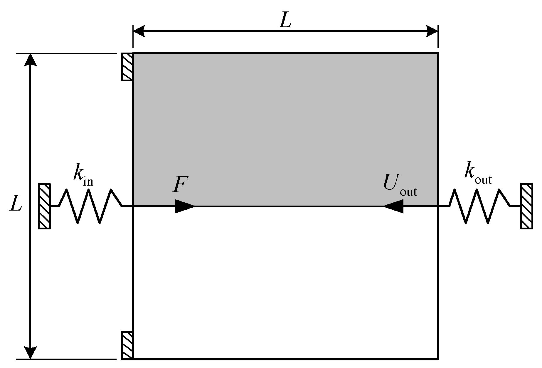
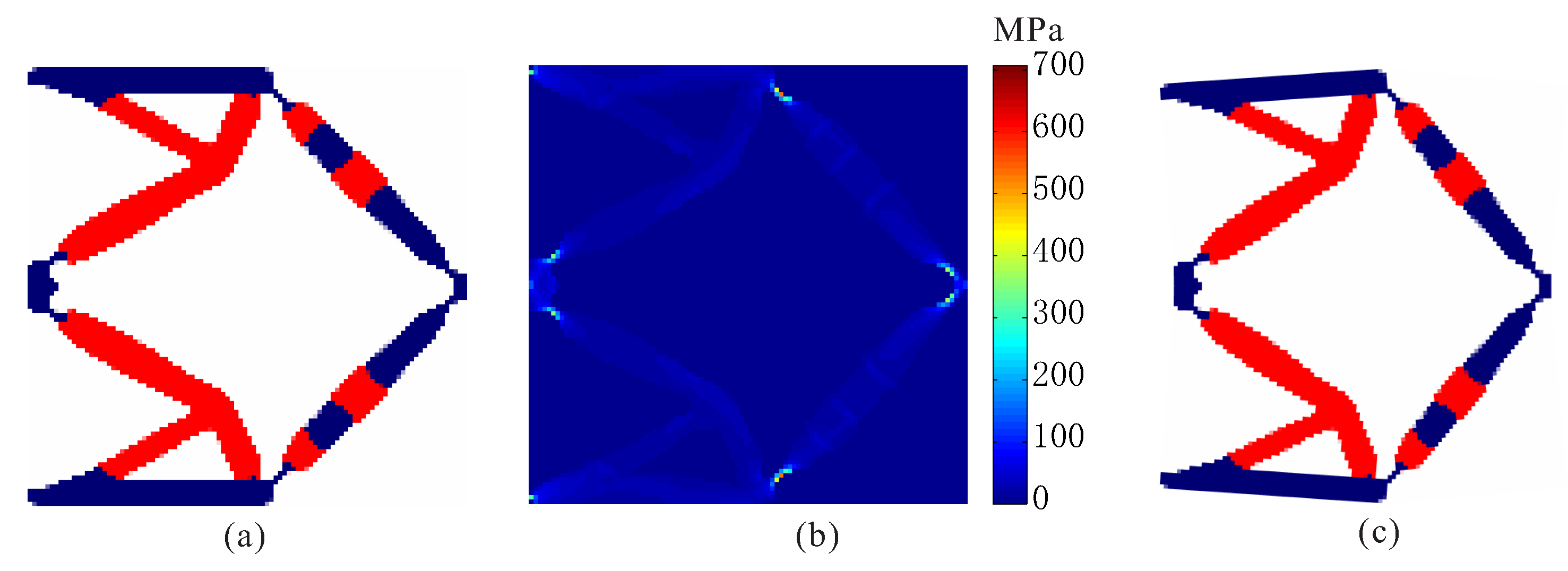
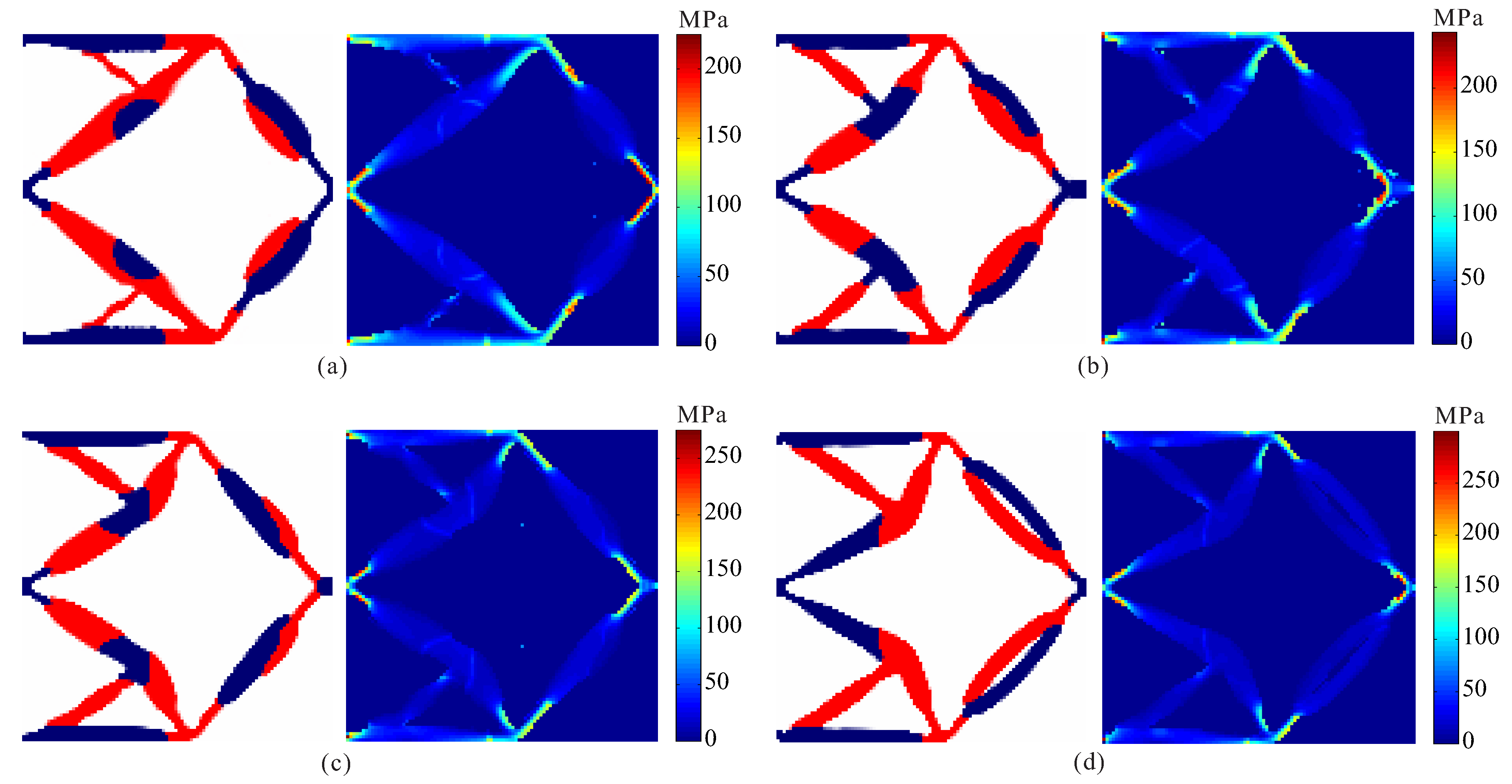
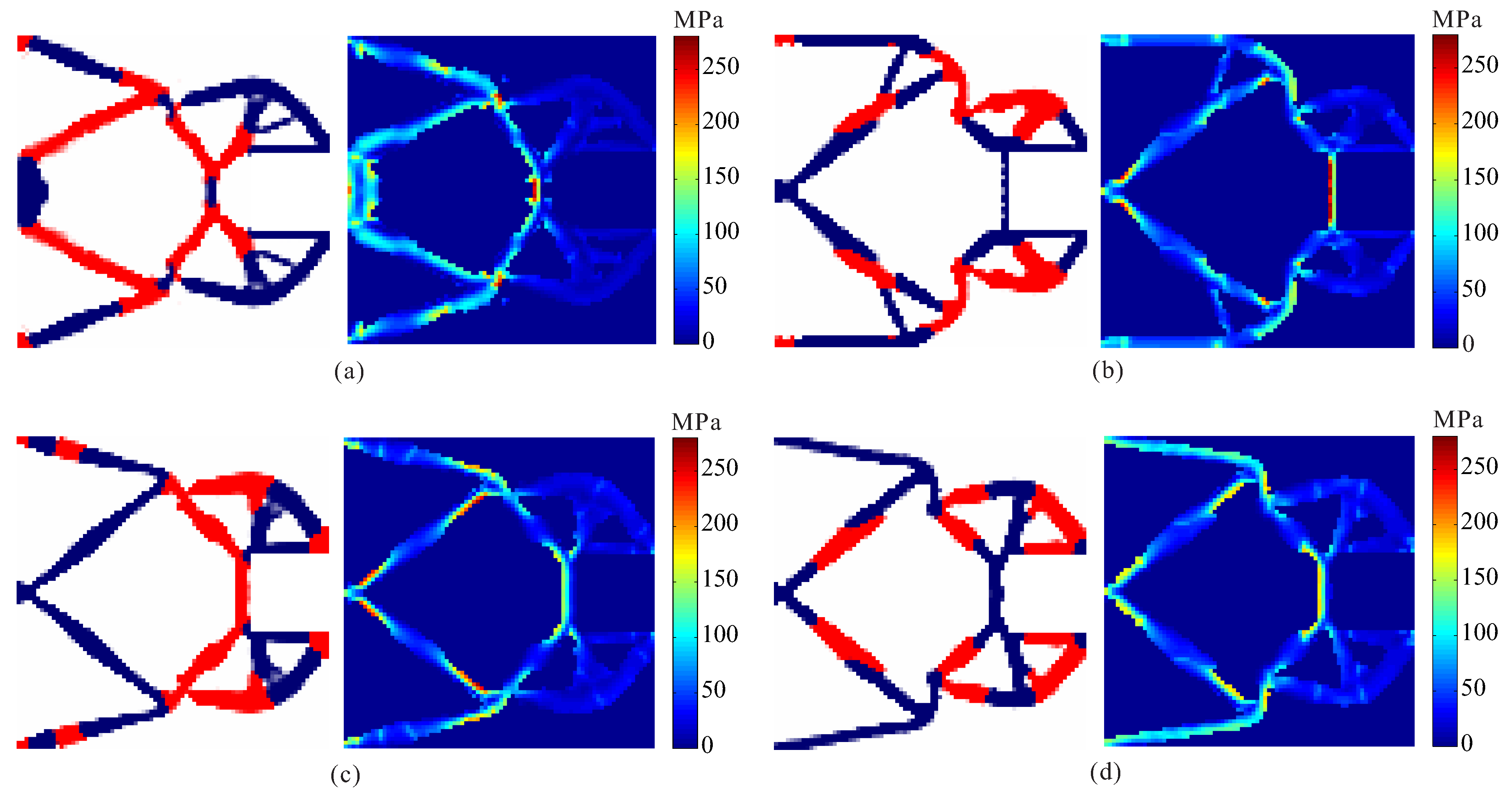
4.1. Displacement Inverter

For the first numerical example, the compliant inverter is to be designed, and the design domain with a square of 300 μm × 300 μm and a thickness of 10 μm is defined as Figure 1. The output port of compliant inverter is expected to generate an opposite output movement compared to the input port. The upper left edge and the lower left edge are fixed. The force loaded at the midpoint of the left side is 65 mN.
The input spring stiffness and the output spring stiffness are k in = 2 × 10³ N/m and k out = 1.6 × 10³ N/m, respectively. Note that, the input and output springs are artificial and they are used to model the interaction between the actuator and the mechanism or the workpiece and the mechanism, the detailed description can be found in the literature [43]. The allowable volume fraction of base material 1 and base material 2 are f 1 = 0.15 and f 1 = 0.125, respectively. Considering the symmetry, only the upper half of the design domain is considered and discretized to 100 × 50 bilinear quadrilateral elements.
To verify the proposed method, topological design of two materials compliant mechanisms without stress constraints is performed firstly. In the topology optimization problem without stress constraints, the objective is developed as maximizing output displacement subject to volume constraints. The optimal layout of two-material compliant inverter obtained by the optimization model without stress constraints is shown in Figure 2. The red regions represent weak material and the blue regions denote strong material in the obtained inverter layout. As shown, one can find that de facto hinges obviously occur in the obtained compliant inverter, which cause stress concentrations. The maximum von Mises stresses are 329.432 MPa in weak material and 706.668 MPa in strong material, respectively. The output displacement of the obtained compliant inverter is 14.930 μm.
Topological design of two-material compliant inverter with global stress constraints is performed. The allowable stresses are σ 1 * = 275 MPa for the weak material and σ 2 * = 350 MPa for the strong material, respectively. The optimal layout of the compliant inverter is obtained in Figure 3. Figure 4 shows the convergence histories of the output displacement, stress constraints, volume constraints and scaling coefficient for topological design of compliant inverter with global stress constraints. The optimization for this example converges after 1000 iterations. There will generally be relatively large oscillations in the initial stage because the volume of each material is reduced to meet the volume constraints. In addition, this is a multi-constraint optimization problem (two volume constraints and two stress constraints), in order to satisfy multiple constraints at the same time, oscillations may occur in the middle stage of optimization. The maximum von Mises stresses are 273.506 MPa in weak material and 349.561 MPa in strong material, respectively. One can notice that de facto hinges is effectively eliminated in the obtained compliant inverter and stress constraints for two materials can be met. By comparing stress distribution in Figure 2b and Figure 3b, one can see that the stress in the compliant inverter obtained by the proposed method is more uniformly distributed. It is demonstrated that the proposed method is effective for topological design of two materials inverter with global stress constraints. The output displacement of the obtained compliant inverter is 14.769 μm. The output displacement of the compliant inverter obtained by stress-based topology optimization is smaller than that of the inverter obtained by topology optimization without stress constraints. This is because the stress constraints limit the maximization of the output displacement to a certain degree.
In order to investigate the effects of different stress constraints on the performance of optimal design, topological design of two-material compliant inverter is performed under different constraint limits for two materials. Comparison of optimal results obtained by topological design of multi-material compliant inverter with global stress constraints is given in Figure 5 and Table 1. From Table 1, one can find that the stress constraints for the weak and strong materials can be satisfied in all the case. It is observed that the optimal topologies of compliant inverter are different under different constraint limits in Figure 5. The hinge-free compliant inverters without de facto hinges can be obtained by using multi-material topology optimization model with global stress constraints. One can observe that as the stress constraint limits for two materials decreases, the output displacement of the obtained compliant inverters also lowers, and the stress is more uniformly distributed.

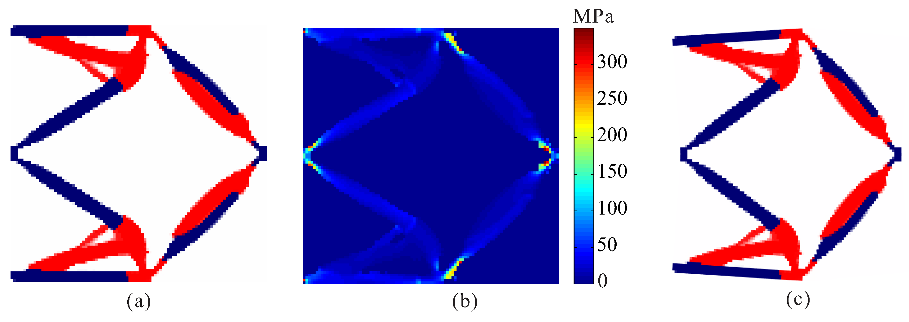
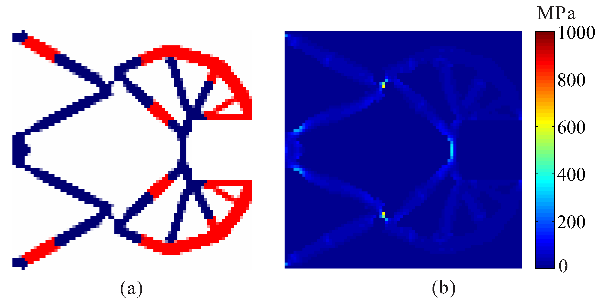
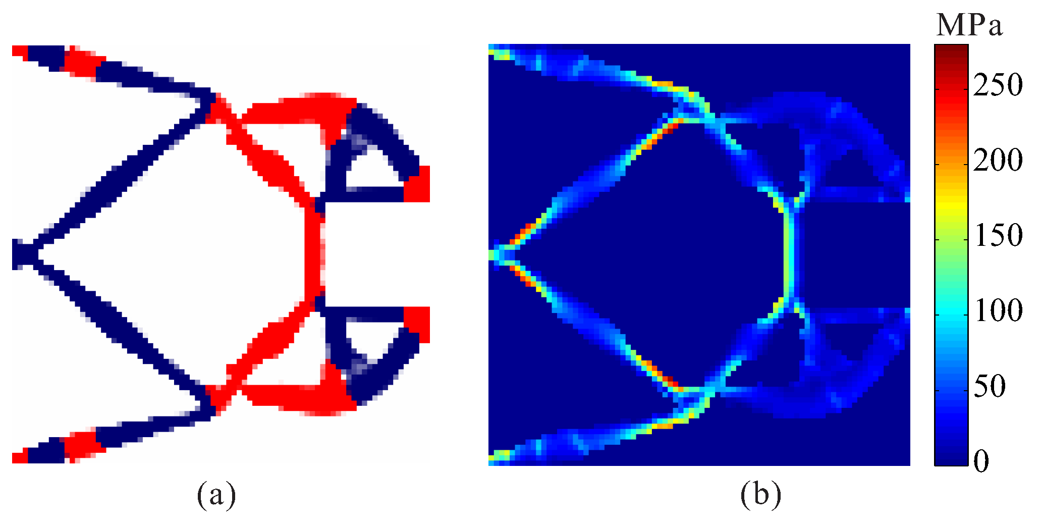
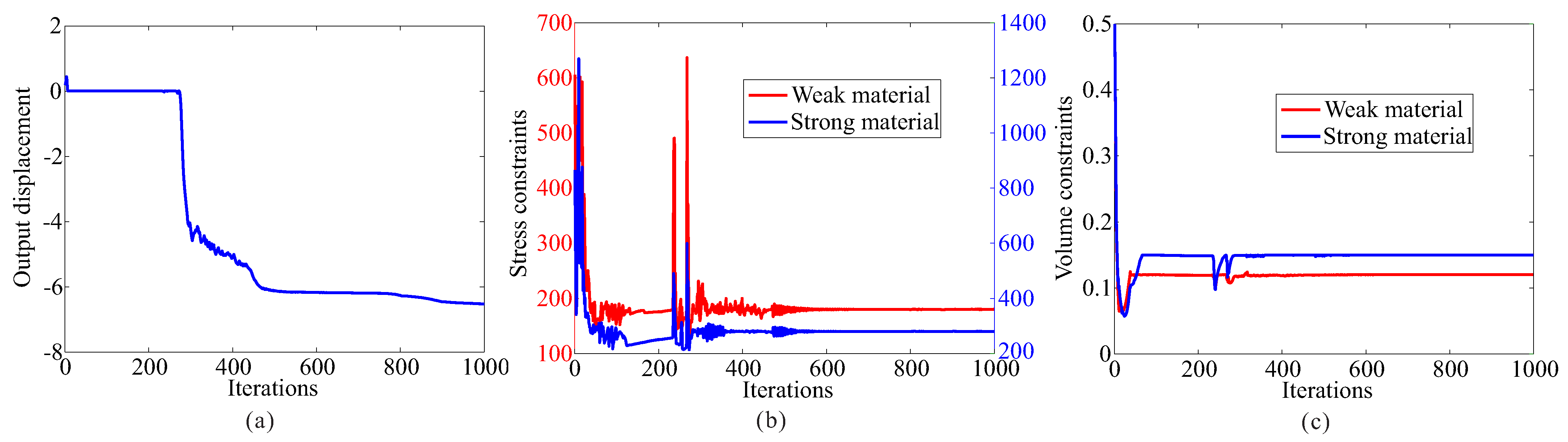
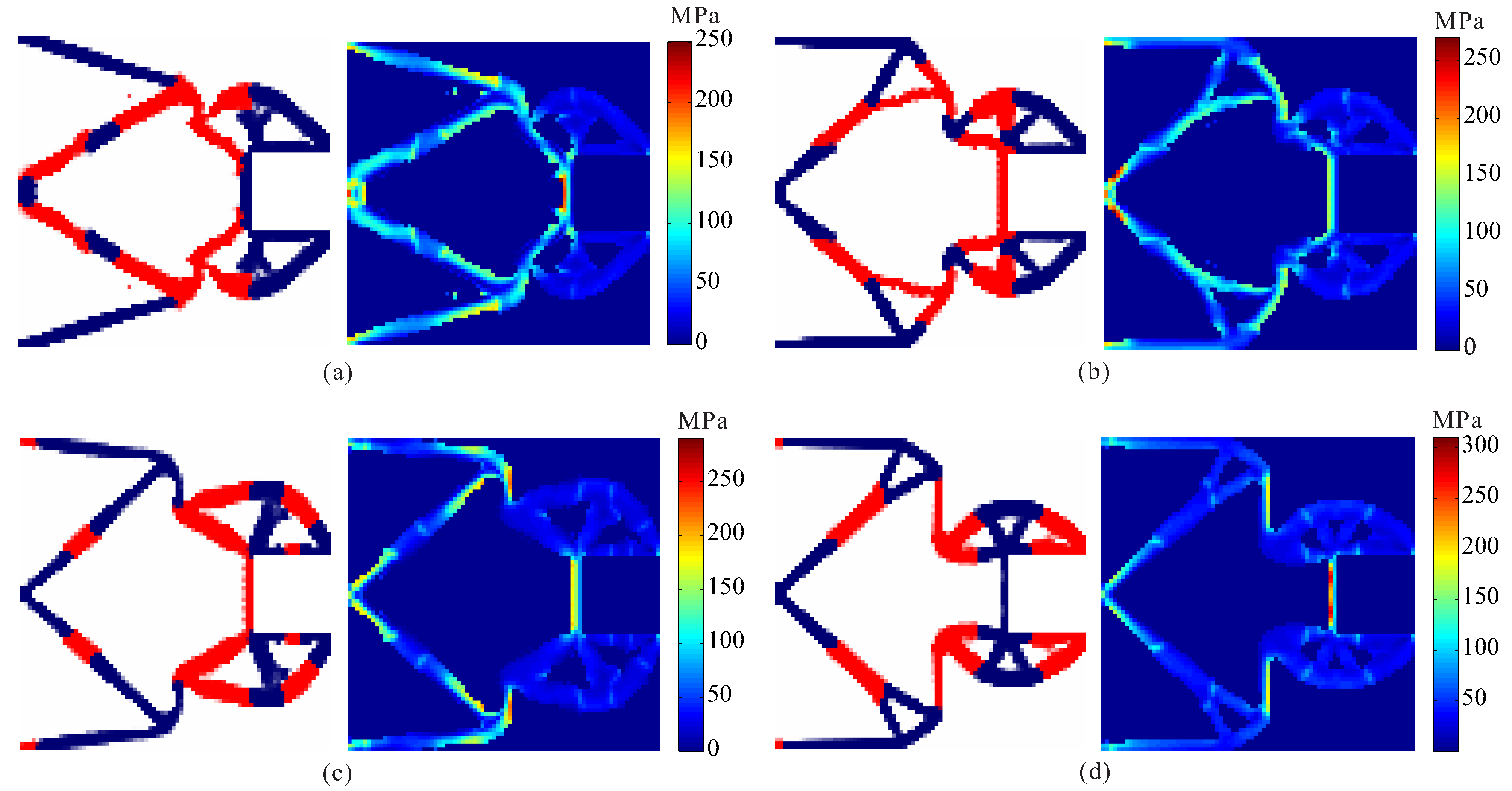
4.2. Compliant Gripper

In this example, the compliant gripper is to be designed, and the design domain with a square of 240 μm × 240 μm and a thickness of 10 μm is defined as Figure 6. The upper left edge and the lower left edge are fixed. The force loaded at the midpoint of the left side is 65 mN. The input spring stiffness and the output spring stiffness are k in = 3 × 10³ N/m and k out = 3 × 10³ N/m, respectively. The allowable volume fraction of weak material and strong material are f 1 = 0.120 and f 1 = 0.150, respectively. Considering the symmetry, only the upper half of the design domain is discretized by 80 × 40 bilinear quadrilateral elements for finite element analysis.
Topological design of two-material compliant gripper without stress constraints and with stress constraints are performed. The optimal layout of two materials compliant gripper obtained by the optimization model without stress constraints is shown in Figure 7. One can see that de facto hinges obviously occurs in the compliant gripper, causing stress concentrations. The maximum von Mises stresses are 227.924 MPa in weak material and 1001.756 MPa in strong material, respectively. The output displacement of the optimal gripper obtained by topology optimization without stress constraints is 7.341 μm.
The allowable stresses are σ 1 * = 180 MPa for the weak material and σ 2 * = 280 MPa for the strong material, respectively. Figure 8 shows the optimal topology of multi-material compliant gripper obtained by the optimization model with global stress constraints. The maximum von Mises stresses in weak material and in strong material are 180.234 MPa and 279.946 MPa, respectively. Figure 9 shows the convergence histories of the output displacement, stress constraints and volume constraints for topological design of gripper with global stress constraints. The optimization for this example converges after 1000 iterations. There will generally be relatively large oscillations in the initial stage because the volume of each material is reduced to meet the volume constraints. In addition, this is a multi-constraint optimization problem, in order to satisfy multiple constraints at the same time, oscillations may occur in the middle stage of optimization. One can notice that the de facto hinges are effectively avoided in the compliant gripper and stress constraints for both weak material and strong material are met. By comparing the maximum stress in Figure 7b and Figure 8b, one can see that the stress in the compliant gripper obtained by the proposed method is more uniformly distributed. It is demonstrated that the proposed method is effective for topological design of two-material compliant gripper with global stress constraints. The output displacement of the obtained gripper is 6.526 μm. The output displacement of the gripper obtained by stress-based topology optimization is smaller than that of the gripper obtained by topology optimization without stress constraints. This is because the stress constraints limit the maximization of the output displacement to a certain degree.
Topological design of two-material compliant gripper is performed under different constraint limits for two materials. Comparison of optimal results obtained by topological design of multi-material compliant gripper with global stress constraints is given in Figure 10 and Table 2. The optimal topologies of compliant grippers obtained by topology optimization under different constraint limits are different, and the stress constraints for each material are met in all the cases. It is observed that the hinge-free compliant grippers can be obtained by multi-material topology optimization model with global stress constraints. One can observe that as the stress constraint limits for two materials decreases, the output displacement of the obtained compliant grippers also lowers, and the stress is more uniformly distributed.
In order to investigate the effects of different output spring stiffness on the performance of optimized design, stress-based topology optimization of two materials compliant gripper is performed with different output spring stiffness. The allowable stresses are σ 1 * = 180 MPa, σ 2 * = 280 MPa for the weak material and the strong material, respectively. The optimal topologies and stress distribution of the obtained compliant grippers are shown in Figure 11. The optimal topologies of compliant grippers obtained by topology optimization under different output spring stiffness are different, and the stress constraints for each material are met in all the cases. It is observed that the output spring stiffness decreases, and the output displacement of the obtained compliant grippers increases, as shown in Table 3.

5. Conclusions

A method for topology optimization of multi-material compliant mechanisms with global stress constraints was put forward. The output displacement of multi-material compliant mechanisms is maximized under the constraints of the maximum stress and the structural volume of each material. The modified P-norm method is applied to aggregate the local von Mises stress constraints for all the finite elements to a global stress constraint. The method of moving asymptotes is utilized to update the topology optimization problem
Several numerical examples are presented to demonstrate the effectiveness of the proposed method. Comparing the results obtained by the model without stress constraints, the appearance of undesirable de facto hinges in the optimal mechanisms can be suppressed effectively by using the topology optimization model with global stress constraints, and the stress constraints for multiple materials are all met in all the cases. The optimal topologies of compliant mechanisms obtained by topology optimization with different constraint limits are different. As the stress constraint limits for two materials decreases, the output displacement of the obtained compliant mechanisms also lowers, and the stress is more uniformly distributed. The topologies of compliant mechanisms obtained by topological design under different output spring stiffness are also different. As the output spring stiffness decreases, the output displacement of the compliant mechanisms increases.
Compliant mechanisms may undergo large deformation during actual operation. Multi-material topology optimization of large-displacement compliant mechanisms with global stress constraints will be investigated in the near future.

Author Contributions

J.Z. and Y.L. wrote the code for topology optimization of multi-material compliant mechanisms with global stress constraints. J.Z. wrote the manuscript; Z.L. and M.L. reviewed and edited. All authors analyzed the data, discussed the results and commented on the manuscript. All authors have read and agreed to the published version of the manuscript.

Funding

This research was funded by National Natural Science Foundation of China (Grant Nos. 52065019, 52165002, and 51665011) and Natural Science Foundation of Jiangxi Province, China (Grant Nos. 20202BAB204015, 20202ACBL214013, and 20192BAB21602).

Acknowledgments

We thank Krister Svanberg for providing the source code of MMA.

Conflicts of Interest

The authors declare no competing interest.

References

  1. Howell, L.L. Compliant Mechanisms; Wiley: New York, NY, USA, 2001. [Google Scholar]
  2. Li, H.; Hao, G. Position-Space-Based Design of a Symmetric Spatial Translational Compliant Mechanism for Micro-/Nano-Manipulation. Micromachines 2018, 9, 189. [Google Scholar] [CrossRef] [Green Version]
  3. Zhu, B.; Zhang, X.; Zhang, H.; Liang, J.; Zang, H.; Li, H.; Wang, R. Design of Compliant Mechanisms Using Continuum Topology Optimization: A review. Mech. Mach. Theory 2020, 143, 103622. [Google Scholar] [CrossRef]
  4. Zhu, D.; Zhan, W.; Wu, F.; Simeone, A. Topology Optimization of Spatially Compliant Mechanisms with an Isomorphic Matrix of a 3-UPC Type Parallel Prototype Manipulator. Micromachines 2018, 9, 184. [Google Scholar] [CrossRef] [Green Version]
  5. Liu, M.; Zhan, J.; Zhu, B.; Zhang, X. Topology Optimization of Compliant Mechanism Considering Actual Output Displacement Using Adaptive Output Spring Stiffness. Mech. Mach. Theory 2020, 143, 103728. [Google Scholar] [CrossRef]
  6. Chen, G.; Howell, L.L. Symmetric Equations for Evaluating Maximum Torsion Stress of Rectangular Beams in Compliant Mechanisms. Chin. J. Mech. Eng. 2018, 31, 14. [Google Scholar] [CrossRef] [Green Version]
  7. Bendsøe, M.P.; Kikuchi, N. Generating optimal topologies in structural design using a homogenization method. Comput. Methods Appl. Mech. Eng. 1988, 71, 197–224. [Google Scholar] [CrossRef]
  8. Ananthasuresh, G.K.; Kota, S.; Kikuchi, N. Strategies for systematic synthesis of compliant MEMS. In Proceedings of the ASME Winter Annual Meeting, Chicago, IL, USA, 6–10 November 1994; pp. 677–686. [Google Scholar]
  9. Zhan, J.; Zhang, X. Topology Optimization of Compliant Mechanisms with Geometrical Nonlinearities Using the Ground Structure Approach. Chin. J. Mech. Eng. 2011, 24, 257–263. [Google Scholar] [CrossRef]
  10. Liu, M.; Zhan, J.; Zhu, B.; Zhang, X. Topology optimization of distributed flexure hinges with desired performance. Eng. Optim. 2020, 52, 405–425. [Google Scholar] [CrossRef]
  11. Zhang, W.; Zhong, W.; Guo, X. An explicit length scale control approach in SIMP-based topology optimization. Comput. Methods Appl. Mech. Eng. 2014, 282, 71–86. [Google Scholar] [CrossRef]
  12. Wang, M.Y.; Wang, X.; Guo, D. A level set method for structural topology optimization. Comput. Methods Appl. Mech. Eng. 2003, 192, 227–246. [Google Scholar] [CrossRef]
  13. Luo, Z.; Tong, L.; Wang, M.Y.; Wang, S. Shape and topology optimization of compliant mechanisms using a parameterization level set method. J. Comput. Phys. 2007, 227, 680–705. [Google Scholar] [CrossRef]
  14. Huang, X.; Xie, Y.M. A further review of ESO type methods for topology optimization. Struct. Multidiscip. Optim. 2010, 41, 671–683. [Google Scholar] [CrossRef]
  15. Xia, L.; Xia, Q.; Huang, X.; Xie, Y.M. Bi-directional Evolutionary Structural Optimization on Advanced Structures and Materials: A Comprehensive Review. Arch. Comput. Methods Eng. 2016, 25, 437–478. [Google Scholar] [CrossRef]
  16. Guo, X.; Zhang, W.; Zhong, W. Doing topology optimization explicitly and geometrically—A new moving morphable components based framework. J. Appl. Mech. 2014, 81, 081009. [Google Scholar] [CrossRef]
  17. Yin, L.; Ananthasuresh, G. Topology optimization of compliant mechanisms with multiple materials using a peak function material interpolation scheme. Struct. Multidisc. Optim. 2001, 23, 49–62. [Google Scholar] [CrossRef]
  18. Sigmund, O. Design of multiphysics actuators using topology optimization—Part II: Two-material structures. Comput. Methods Appl. Mech. Eng. 2001, 190, 6605–6627. [Google Scholar] [CrossRef]
  19. Saxena, A. Topology design of large displacement compliant mechanisms with multiple materials and multiple output ports. Struct. Multidisc. Optim. 2005, 30, 477–490. [Google Scholar] [CrossRef]
  20. Wang, M.Y.; Chen, S.; Wang, X.; Mei, Y. Design of Multimaterial Compliant Mechanisms Using Level-Set Methods. J. Mech. Des. 2005, 127, 941–956. [Google Scholar] [CrossRef]
  21. Alonso, C.; Ansola, R.; Querin, O.M. Topology synthesis of multi-material compliant mechanisms with a Sequential Element Rejection and Admission method. Finite Elem. Anal. Des. 2014, 85, 11–19. [Google Scholar] [CrossRef]
  22. Gaynor, A.T.; Meisel, N.A.; Williams, C.B.; Guest, J.K. Multiple-Material Topology Optimization of Compliant Mechanisms Created Via PolyJet Three-Dimensional Printing. J. Manuf. Sci. E-T ASME 2014, 136, 061015. [Google Scholar] [CrossRef] [Green Version]
  23. Zuo, W.; Saitou, K. Multi-material topology optimization using ordered SIMP interpolation. Struct. Multidiscip. Optim. 2017, 55, 477–491. [Google Scholar] [CrossRef]
  24. Wang, N.; Hu, K.; Zhang, X. Hierarchical optimization for topology design of multi-material compliant mechanisms. Eng. Optim. 2017, 49, 2013–2035. [Google Scholar] [CrossRef]
  25. Sigmund, O. Morphology-based black and white filters for topology optimization. Struct. Multidiscip. Optim. 2007, 33, 401–424. [Google Scholar] [CrossRef] [Green Version]
  26. Poulsen, T.A. A new scheme for imposing a minimum length scale in topology optimization. Int. J. Numer. Methods Eng. 2003, 57, 741–760. [Google Scholar] [CrossRef]
  27. Yin, L.; Ananthasuresh, G.K. Design of Distributed Compliant Mechanisms. Mech. Based Des. Struc. 2003, 31, 151–179. [Google Scholar] [CrossRef]
  28. Zhou, H. Topology optimization of compliant mechanisms using hybrid discretization model. J. Mech. Des. 2010, 132, 111003. [Google Scholar] [CrossRef]
  29. Luo, J.; Luo, Z.; Chen, S.; Tong, L.; Wang, M.Y. A new level set method for systematic design of hinge-free compliant mechanisms. Comput. Methods Appl. Mech. Eng. 2008, 198, 318–331. [Google Scholar] [CrossRef]
  30. Wang, M.Y.; Chen, S. Compliant mechanism optimization: Analysis and design with intrinsic characteristic stiffness. Mech. Based Des. Struc. 2009, 37, 183–200. [Google Scholar] [CrossRef]
  31. Zhu, B.; Zhang, X.; Fatikow, S. Level set-based topology optimization of hinge-free compliant mechanisms using a two-step elastic modeling method. J. Mech. Des. 2014, 136, 031007. [Google Scholar] [CrossRef]
  32. Leon, D.M.D.; Alexandersen, J.; Fonseca, J.S.O.; Sigmund, O. Stress-constrained topology optimization for compliant mechanism design. Struct. Multidiscip. Optim. 2015, 52, 1–15. [Google Scholar]
  33. Lopes, C.G.; Novotny, A.A. Topology design of compliant mechanisms with stress constraints based on the topological derivative concept. Struct. Multidiscip. Optim. 2016, 54, 737–746. [Google Scholar] [CrossRef]
  34. Chu, S.; Gao, L.; Xiao, M.; Luo, Z.; Li, H. Stress-based multi-material topology optimization of compliant mechanisms. Int. J. Numer. Methods Eng. 2018, 113, 1021–1044. [Google Scholar] [CrossRef]
  35. Yoon, G.H.; Park, Y.K.; Kim, Y.Y. Element stacking method for topology optimization with material-dependent boundary and loading conditions. J. Mech. Mater. Struct. 2007, 2, 883–895. [Google Scholar] [CrossRef]
  36. Jeong, S.H.; Choi, D.; Yoon, G.H. Separable stress interpolation scheme for stress-based topology optimization with multiple homogenous materials. Finite Elem. Anal. Des. 2014, 82, 16–31. [Google Scholar] [CrossRef]
  37. Zhang, W.; Li, D.; Zhou, J.; Du, Z.; Li, B.; Guo, X. A moving morphable void (MMV)-based explicit approach for topology optimization considering stress constraints. Comput. Methods Appl. Mech. Eng. 2018, 334, 381–413. [Google Scholar] [CrossRef]
  38. Le, C.; Norato, J.; Bruns, T.; Ha, C.; Tortorelli, D. Stress-based topology optimization for continua. Struct. Multidiscip. Optim. 2010, 41, 605–620. [Google Scholar] [CrossRef]
  39. Holmberg, E.; Bo, T.; Klarbring, A. Stress constrained topology optimization. Struct. Multidiscip. Optim. 2013, 48, 33–47. [Google Scholar] [CrossRef] [Green Version]
  40. Oest, J.; Lund, E. Topology optimization with finite-life fatigue constraints. Struct. Multidiscip. Optim. 2017, 56, 1–15. [Google Scholar] [CrossRef] [Green Version]
  41. Andreassen, E.; Clausen, A.T.; Schevenels, M.; Lazarov, B.S.; Sigmund, O. Efficient topology optimization in MATLAB using 88 lines of code. Struct. Multidiscip. Optim. 2011, 43, 1–16. [Google Scholar] [CrossRef] [Green Version]
  42. Svanberg, K. The Method of Moving Asymptotes—A New Method for Structural Optimization. Int. J. Numer. Methods Eng. 1987, 24, 359–373. [Google Scholar] [CrossRef]
  43. Sigmund, O. On the design of compliant mechanisms using topology optimization. Mech. Struct. Mach. 1997, 25, 493–524. [Google Scholar] [CrossRef]
Figure 1. Design domain of compliant inverter.
Micromachines 12 01379 g001
Figure 2. The results for topological design of multi-material compliant inverter without stress constraints. (a) Optimal topology; (b) stress distribution; (c) deformed configuration.
Micromachines 12 01379 g002
Figure 3. The results for topological design of multi-material compliant inverter with stress constraints ( σ 1 * = 275 MPa, σ 2 * = 350 MPa). (a) Optimal topology; (b) stress distribution; (c) deformed configuration.
Micromachines 12 01379 g003
Figure 4. The convergence history for topological design of multi-material compliant inverter with global stress constraints ( σ 1 * = 275 MPa, σ 2 * = 350 MPa). (a) Output displacement; (b) stress constraints; (c) volume constraints; (d) scaling coefficient.
Micromachines 12 01379 g004
Figure 5. The results for topological design of multi-material compliant inverter under different stress constraint limits. (a) σ 1 * = 150 MPa, σ 2 * = 225 MPa; (b) σ 1 * = 175 MPa, σ 2 * = 250 MPa; (c) σ 1 * = 200 MPa, σ 2 * = 275 MPa; (d) σ 1 * = 225 MPa, σ 2 * = 300 MPa.
Micromachines 12 01379 g005
Figure 6. Design domain of compliant gripper.
Micromachines 12 01379 g006
Figure 7. The results for topological design of multi-material compliant gripper without stress constraints. (a) Optimal topology; (b) stress distribution.
Micromachines 12 01379 g007
Figure 8. The convergence history for topological design of multi-material compliant gripper with global stress constraints ( σ 1 * = 180 MPa, σ 2 * = 280 MPa). (a) Optimal topology; (b) stress distribution.
Micromachines 12 01379 g008
Figure 9. The convergence history for topological design of multi-material compliant gripper with global stress constraints ( σ 1 * = 180 MPa, σ 2 * = 280 MPa). (a) Output displacement; (b) stress constraints; (c) volume constraints.
Micromachines 12 01379 g009
Figure 10. The results for topological design of multi-material compliant gripper under different stress constraint limits. (a) σ 1 * = 150 MPa, σ 2 * = 250 MPa; (b) σ 1 * = 170 MPa, σ 2 * = 270 MPa; (c) σ 1 * = 190 MPa, σ 2 * = 290 MPa; (d) σ 1 * = 210 MPa, σ 2 * = 310 MPa.
Micromachines 12 01379 g010
Figure 11. The results for topological design of multi-material compliant gripper under different output spring stiffness. (a) k out = 1 × 10³ N/m; (b) k out = 2 × 10³ N/m; (c) k out = 3 × 10³ N/m; (d) k out = 4 × 10³ N/m.
Micromachines 12 01379 g011
Table 1. Optimal results for compliant inverter under different stress constraint limits.
Stress ConstraintsOutput Displacement
(μm)
Maximum Stress (MPa)
σ 1 *   ( MPa ) σ 2 *   ( MPa ) Weak MaterialStrong Material
15022513.361149.538224.976
17525013.941172.011243.847
20027514.376200.065275.011
22530014.587224.986299.837
Table 2. Optimal results for compliant gripper under different stress constraint limits.
Stress ConstraintsOutput Displacement
(μm)
Maximum Stress (MPa)
σ 1 *   ( MPa ) σ 2 *   ( MPa ) Weak MaterialStrong Material
1502505.199151.192250.275
1702705.914169.814269.678
1902907.055191.839290.063
2103107.125202.027310.068
Table 3. Optimal results for compliant gripper under different output spring stiffness.
Output Spring Stiffness
k out (N/m)
Output Displacement
(μm)
Maximum Stress (MPa)
Weak MaterialStrong Material
1 × 1039.168180.064280.571
2 × 1037.579179.894279.709
3 × 1036.526180.234279.946
4 × 1035.239177.928280.065
Publisher’s Note: MDPI stays neutral with regard to jurisdictional claims in published maps and institutional affiliations.

