
Bio-Inspired Take-Off Maneuver and Control in Vertical Jumping for Quadruped Robot with Manipulator

 , ,
, ,  ,
,
Abstract
:1. Introduction
- (1)
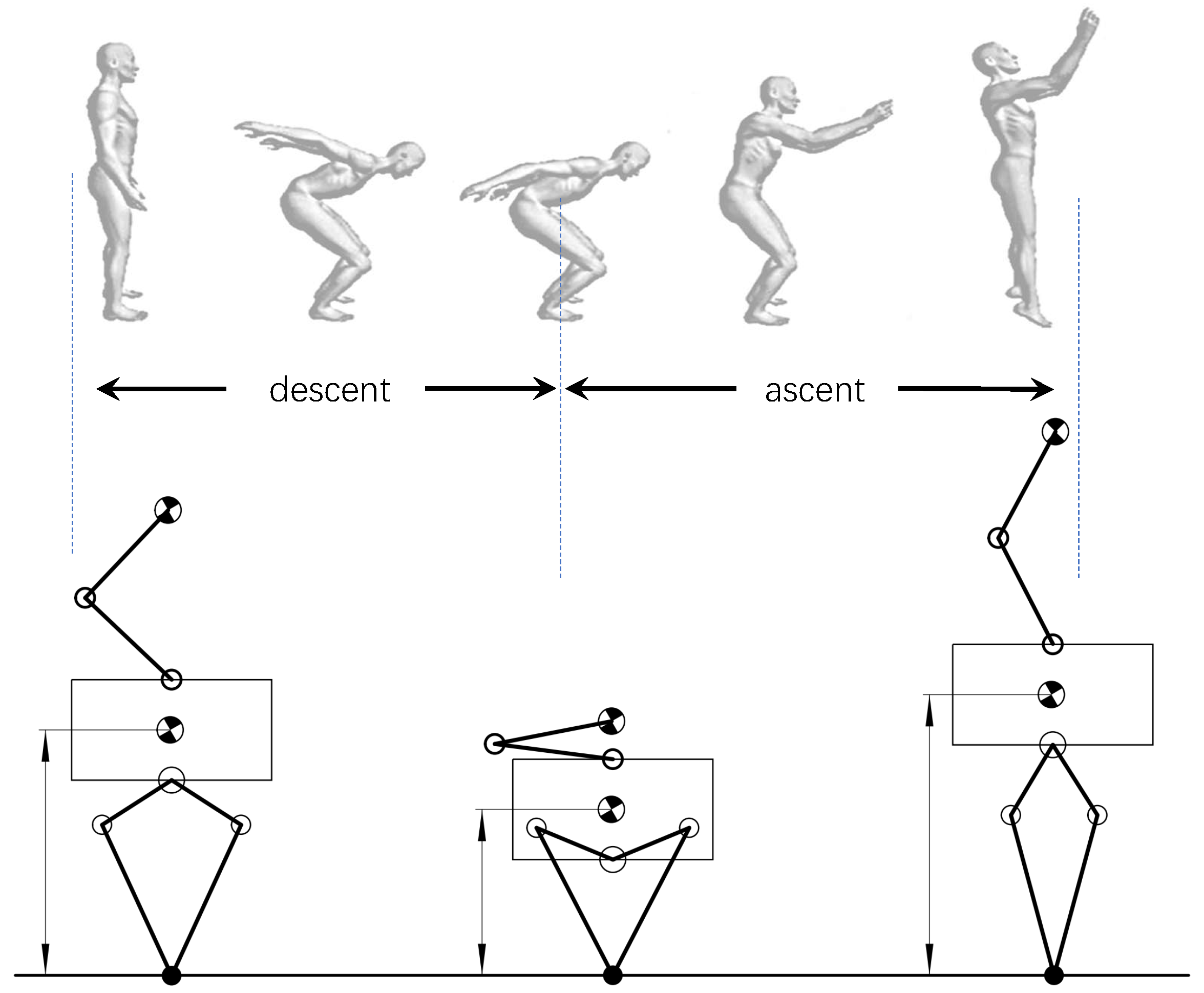
- To improve the jumping height of a quadruped robot with a manipulator, a bio-inspired take-off maneuver based on the coordination of upper and lower limbs was proposed in this paper. The kinetic energy and potential energy of the system are increased by driving the manipulator-end (ME) to swing upward, and the torso driven by the legs will delay reaching the required peak speed due to the additional load caused by the accelerated ME. When the acceleration of ME is less than zero, it will pull the body upward, which reduces the peak power of the leg joints. Therefore, the jumping ability of the system is improved. Furthermore, the optimal jumping planning was obtained by optimizing the trigger time.
- (2)
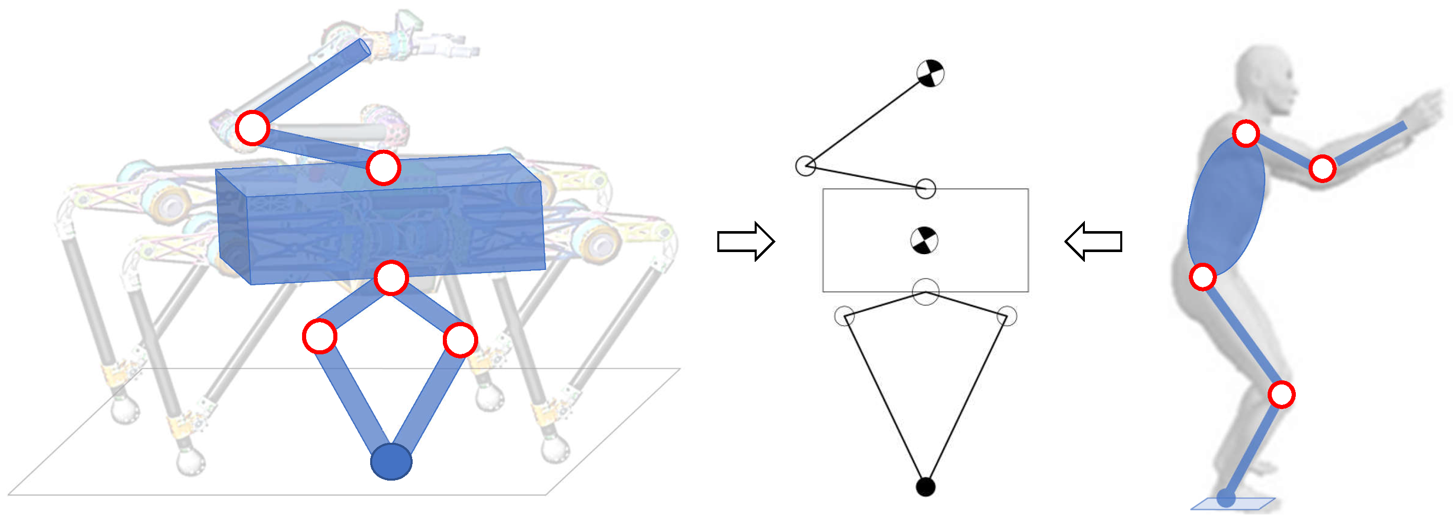
- To realize continuous and stable jumping, a control framework based on whole-body control was established, in which the quadruped robot with a manipulator was simplified into a floating seven-link model, and the hierarchical optimization method was used to solve the target joint torques. This method greatly simplifies the dynamic model and is convenient for calculation.
2. System Overview
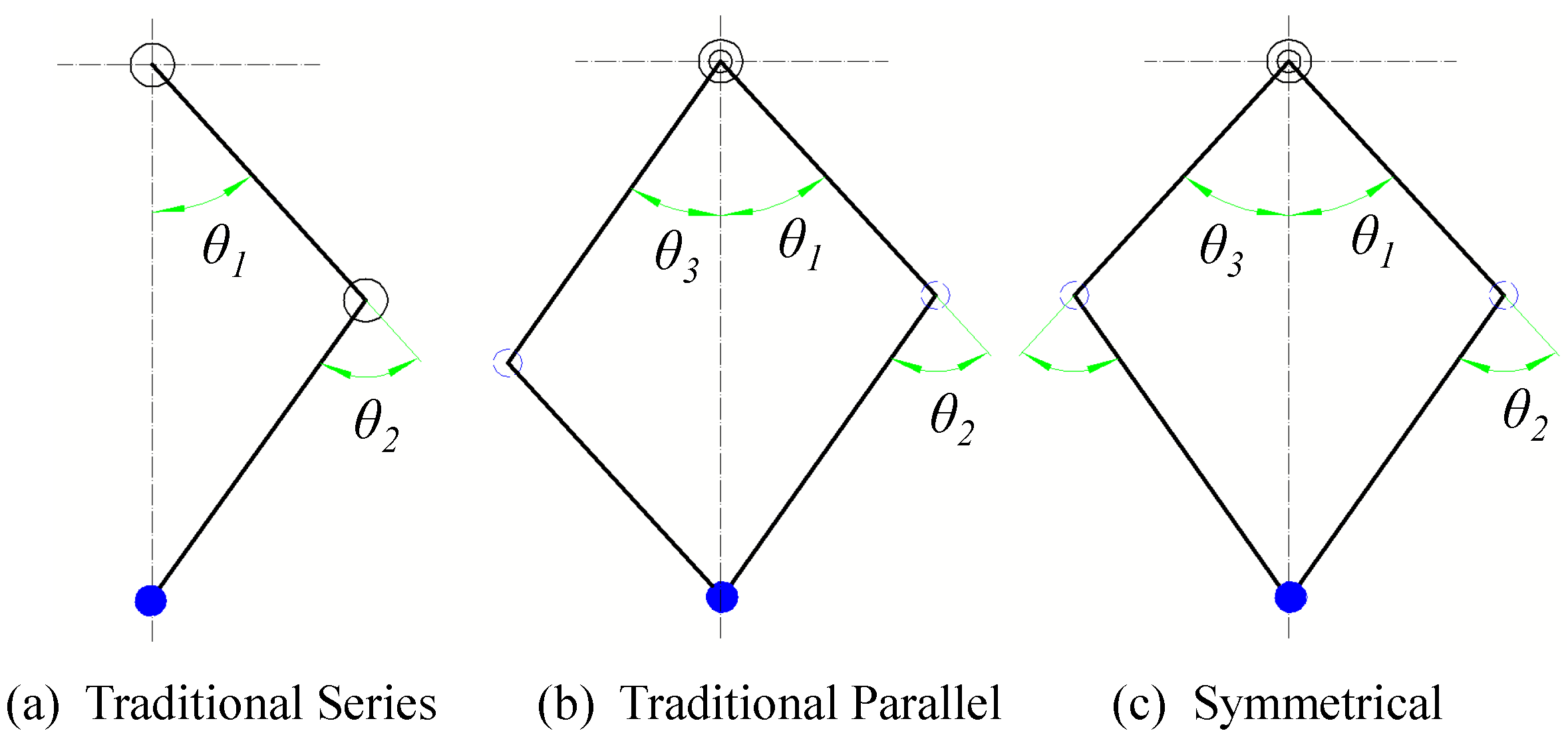
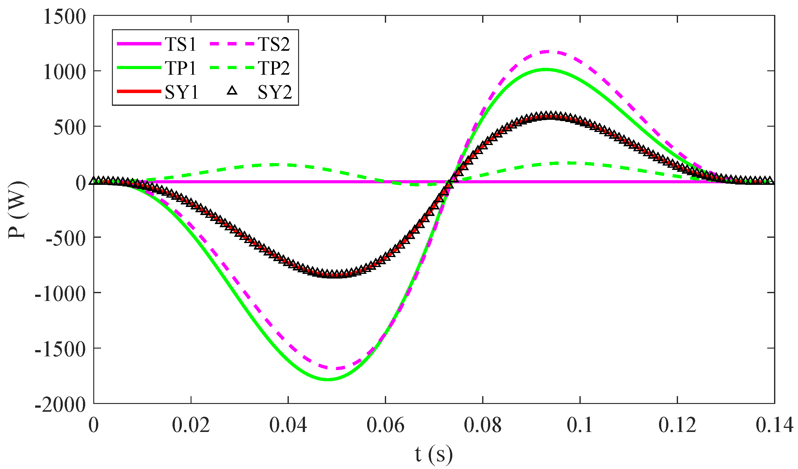
2.1. Leg Structure Selection
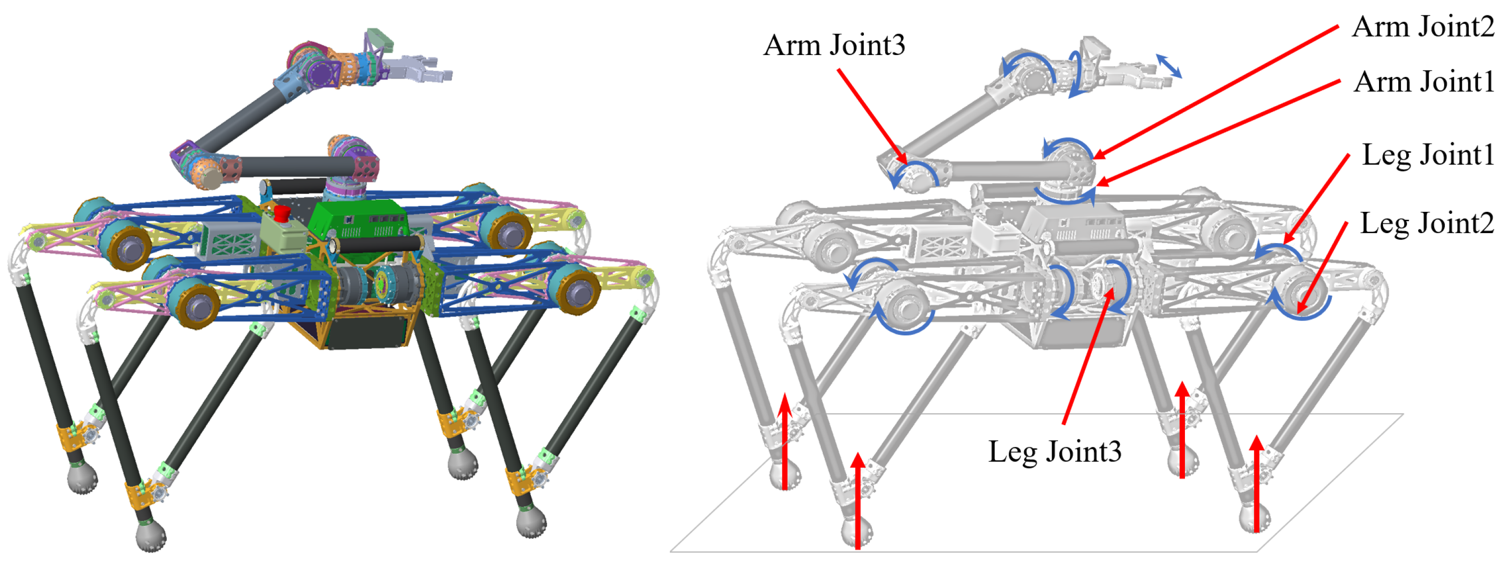
2.2. Quadruped Robot with Manipulator
3. Bio-Inspired Take-Off Maneuver
4. Motion Tracking Based on Whole-Body Control
4.1. Model Formulation
4.2. Whole-Body Control Based on Hierarchical Optimization
4.2.1. Hierarchical Optimization
4.2.2. Task Formulation
- Contact constraint: It is a very important condition to ensure that the support point does not slide with the ground in the support phase of the legged robot, which can be achieved by constraining the target acceleration:where the is the desired acceleration vector of the torso obtained from the planner.
- Motion tracking in operational space: The control goal is to achieve accurate motion tracking and make the system move along the desired trajectory. According to Section 3, it is necessary to ensure the motion of the upper and lower limbs is at the same time in the jumping motion planning. For the pre-planned torso and manipulator trajectory (position, velocity and acceleration), as shown in Figure 6, the motion tracking in the operational space can be realized by the following constraints:where the is the Jacobian of the arm-end motion. The desired acceleration is solved by PD control law and can be divide into three parts: torso position, base orientation and manipulator’s position. Furthermore, the orientation error is obtained using the exponential map representation of rotations, where and R represent the desired and actual base orientation, respectively.
- Energy optimization: Similar to the optimization goal of motion tracking, we can also introduce the task of driving force or torque. These tasks usually have the lowest priority, and it is usually used to improve the energy efficiency of the system:
4.3. Joint Torque Generation
5. Numerical Simulations and Discussions
5.1. Trigger Time Optimization of Arm Swing
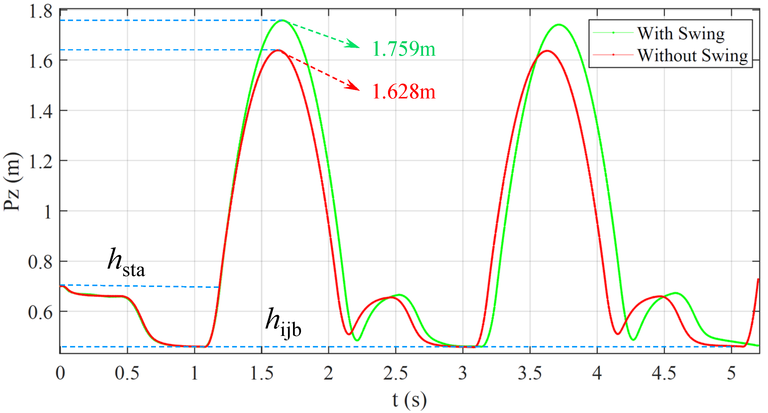
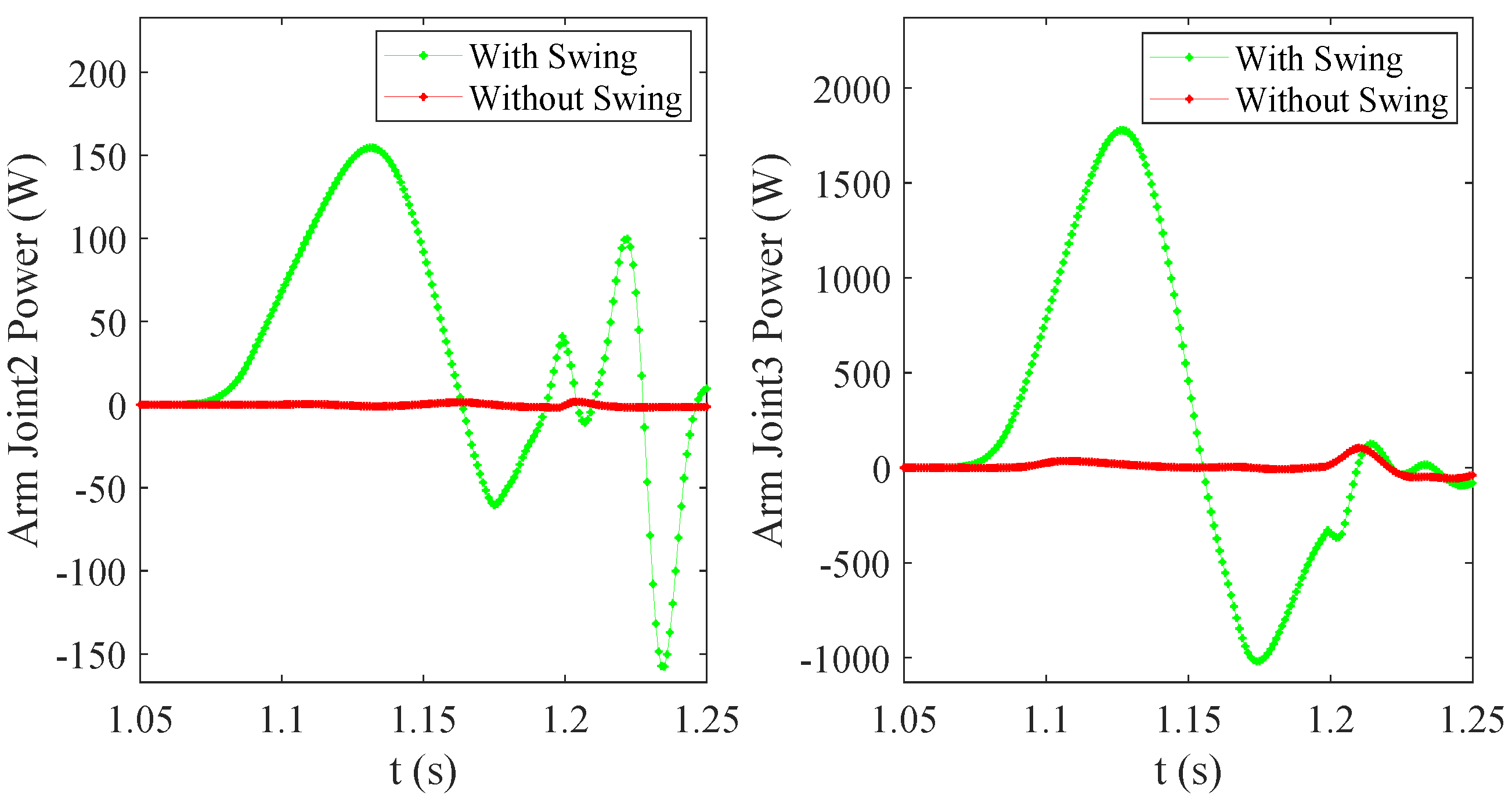
5.2. Comparison of Vertical Jumping with or without Arm Swing
6. Conclusions
Author Contributions
Funding
Conflicts of Interest
References
- Kolvenbach, H.; Hampp, E.; Barton, P.; Zenkl, R.; Hutter, M. Towards jumping locomotion for quadruped robots on the moon. In Proceedings of the 2019 IEEE/RSJ International Conference on Intelligent Robots and Systems (IROS), Macau, China, 3–8 November 2019; pp. 5459–5466. [Google Scholar]
- Bartsch, S.; Manz, M.; Kampmann, P.; Dettmann, A.; Hanff, H.; Langosz, M.; Kirchner, F. Development and control of the multi-legged robot mantis. In Proceedings of the ISR 2016: 47st International Symposium on Robotics, Munich, Germany, 21–22 June 2016; pp. 1–8. [Google Scholar]
- Lehner, P.; Brunner, S.; Dömel, A.; Gmeiner, H.; Riedel, S.; Vodermayer, B.; Wedler, A. Mobile manipulation for planetary exploration. In Proceedings of the 2018 IEEE Aerospace Conference, Big Sky, MT, USA, 3–10 March 2018; pp. 1–11. [Google Scholar]
- Kolvenbach, H.; Arm, P.; Hampp, E.; Dietsche, A.; Bickel, V.; Sun, B.; Meyer, C.; Hutter, M. Traversing Steep and Granular Martian Analog Slopes with a Dynamic Quadrupedal Robot. arXiv 2021, arXiv:2106.01974. [Google Scholar]
- Raibert, M.; Blankespoor, K.; Nelson, G.; Playter, R. BigDog, the Rough-Terrain Quadruped Robot. World Congress. Proc. World Congr. Int. Fed. Autom. Control. 2008, 41, 10822–10825. [Google Scholar]
- Bledt, G.; Powell, M.J.; Katz, B.; Carlo, J.D.; Wensing, P.M.; Kim, S. MIT Cheetah 3: Design and Control of a Robust, Dynamic Quadruped Robot. In Proceedings of the 2018 IEEE/RSJ International Conference on Intelligent Robots and Systems (IROS), Madrid, Spain, 1–5 October 2018; pp. 2245–2252. [Google Scholar]
- Boston Dynamics: SpotMini. 2018. Available online: https://youtu.be/fUyU3lKzoio (accessed on 5 September 2021).
- Hutter, M.; Gehring, C.; Jud, D.; Lauber, A.; Bellicoso, C.D.; Tsounis, V.; Hwangbo, J.; Bodie, K.; Fankhauser, P.; Bloesch, M.; et al. ANYmal—A highly mobile and dynamic quadrupedal robot. In Proceedings of the 2016 IEEE/RSJ International Conference on Intelligent Robots and Systems (IROS), Daejeon, Korea, 9–14 October 2016; pp. 38–44. [Google Scholar]
- Semini, C.; Barasuol, V.; Goldsmith, J.; Frigerio, M.; Focchi, M.; Gao, Y. Design of the hydraulically-actuated, torque-controlled quadruped robot HyQ2Max. IEEE/ASME Trans. Mechatron. 2016, 22, 635–646. [Google Scholar] [CrossRef]
- Ghost Robotics. 2018. Available online: https://www.youtube.com/channel/UCG4Xp4nghgyWK4ud5Xbo-4g (accessed on 30 August 2021).
- Aliengo. 2021. Available online: https://www.unitree.com/products/aliengo (accessed on 25 August 2021).
- Abe, Y.; Stephens, B.; Murphy, M.; Rizzi, A. Dynamic whole- body robotic manipulation. In Proceedings of the Unmanned Systems Technology XV, Baltimore, MD, USA, 17 May 2013; Volume 8741. [Google Scholar]
- Rehman, B.; Focchi, M.; Lee, J.; Dallali, H.; Caldwell, D.; Semini, C. Towards a multi-legged mobile manipulator. In Proceedings of the 2016 IEEE International Conference on Robotics and Automation (ICRA), Stockholm, Sweden, 16–21 May 2016; pp. 3618–3624. [Google Scholar]
- Bellicoso, D.; Krmer, K.; Stuble, M.; Sako, D.; Hutter, M. ALMA-Articulated Locomotion and Manipulation for a Torque-Controllable Robot. In Proceedings of the 2019 IEEE International Conference on Robotics and Automation (ICRA), Montreal, QC, Canada, 20–24 May 2019; pp. 8477–8483. [Google Scholar]
- Sleiman, J.; Farshidian, F.; Minniti, M.; Hutter, M. A unified MPC framework for whole-body dynamic locomotion and manipulation. IEEE Robot. Autom. Lett. 2021. [Google Scholar] [CrossRef]
- Pavei, G.; Biancardi, C.M.; Minetti, A.E. Skipping vs. running as the bipedal gait of choice in hypogravity. J. Appl. Physiol. 2015, 119, 93–100. [Google Scholar] [CrossRef] [PubMed] [Green Version]
- Nguyen, Q.; Powell, M.; Katz, B.; Di Carlo, J.; Kim, S. Optimized jumping on the mit cheetah 3 robot. In Proceedings of the 2019 International Conference on Robotics and Automation (ICRA), Montreal, QC, Canada, 20–24 May 2019; pp. 7448–7454. [Google Scholar]
- Park, H.; Wensing, P.; Kim, S. Jumping over obstacles with MIT Cheetah 2. Rob. Auton. Syst. 2021, 136, 103703. [Google Scholar] [CrossRef]
- Bellegarda, G.; Nguyen, Q. Robust quadruped jumping via deep reinforcement learning. arXiv 2020, arXiv:2011.07089. [Google Scholar]
- Kang, R.; Meng, F.; Chen, X.; Yu, Z.; Fan, X.; Ming, A.; Huang, Q. Structural Design and Crawling Pattern Generator of a Planar Quadruped Robot for High-Payload Locomotion. Sensors. 2020, 20, 6543. [Google Scholar] [CrossRef] [PubMed]
- Hara, M.; Shibayama, A.; Arakawa, H.; Fukashiro, S. Effect of arm swing direction on forward and backward jump performance. J. Biomech. 2008, 41, 2806–2815. [Google Scholar] [CrossRef] [PubMed]
- Nishiguchi, J.; Minami, M.; Yanou, A.; Matsuno, T.; Maeba, T. Analyses of jumping motion of humanoid robot using arms’ swinging. In Proceedings of the SICE Annual Conference (SICE), Akita, Japan, 20–23 August 2012; pp. 496–501. [Google Scholar]
- Adrian, L.; Jos, V.; Dirk, D. Understanding how an arm swing enhances performance in the vertical jump. J. Biomech. 2004, 37, 1929–1940. [Google Scholar]
- Mineshita, H.; Otani, T.; Sakaguchi, M.; Kawakami, Y.; Takanishi, A. Jumping Motion Generation for Humanoid Robot Using Arm Swing Effectively and Changing in Foot Contact Status. In Proceedings of the 2020 IEEE/RSJ International Conference on Intelligent Robots and Systems (IROS), Las Vegas, NV, USA, 24–26 October 2020; pp. 3823–3828. [Google Scholar]
- Bellicoso, C.; Gehring, C.; Hwangbo, J.; Fankhauser, P.; Hutter, M. Perception-less terrain adaptation through whole body control and hierarchical optimization. In Proceedings of the 2016 IEEE-RAS International Conference on Humanoid Robots (Humanoids), Cancun, Mexico, 15–17 November 2016; pp. 558–564. [Google Scholar]


| Priority | Task |
|---|---|
| 1 | Equations of Motion |
| No contact motion | |
| Torque limits | |
| Friction cone limits | |
| 2 | Torso position tracking |
| Torso orientation tracking | |
| Manipulator motion tracking | |
| 3 | Contact force minimization |
| Joint torque minimization |
| Symbol | Items | Values |
|---|---|---|
| Total mass | 43 kg | |
| Single leg mass | 1.4 kg | |
| Manipulator mass | 8 kg | |
| Manipulator-end mass | 3 kg | |
| Length of robot | 1.2 m | |
| Width of robot | 0.4 m | |
| Length of Manipulator | 0.76 m | |
| Jump period | 0.14 s | |
| Control period | 1 ms | |
| Stance height | 0.7 m | |
| Leaving height | 0.75 m | |
| Initial height of base | 0.45 m | |
| Maximum height of manipulator-end | 0.7 m | |
| Initial height of manipulator-end | 0.2 m | |
| Earth’s gravitational acceleration | 9.8 m/s |
| (s) | −0.06 | −0.04 | −0.02 | 0 | 0.02 | 0.04 | 0.06 |
| (m) | 1.724 | 1.738 | 1.751 | 1.759 | 1.757 | 1.729 | 1.676 |
| Environment | g (m/s) | Condition | (W) | (W) | (W) | (W) | (m) | |
|---|---|---|---|---|---|---|---|---|
| Earth (flat ground) | 9.8 | with swing | 770 | 998 | 157 | 1776 | 1.759 | 19 |
| without swing | 816 | 1043 | 0 | 0 | 1.628 | |||
| Mars (flat ground) | 3.71 | with swing | 848 | 1028 | 140 | 1830 | 3.766 | 17.1 |
| without swing | 903 | 1104 | 0 | 0 | 3.405 | |||
| Moon (flat ground) | 1.63 | with swing | 778 | 971 | 159 | 1862 | 7.632 | 15.4 |
| without swing | 928 | 1106 | 0 | 0 | 6.9 | |||
| Earth (15° slope) | 9.8 | with swing | 802 | 922 | 287 | 1460 | 1.873 | 17.4 |
| without swing | 860 | 983 | 0 | 0 | 1.764 |
Publisher’s Note: MDPI stays neutral with regard to jurisdictional claims in published maps and institutional affiliations. |
© 2021 by the authors. Licensee MDPI, Basel, Switzerland. This article is an open access article distributed under the terms and conditions of the Creative Commons Attribution (CC BY) license (https://creativecommons.org/licenses/by/4.0/).
Share and Cite
Kang, R.; Meng, F.; Wang, L.; Chen, X.; Yu, Z.; Fan, X.; Sato, R.; Ming, A.; Huang, Q. Bio-Inspired Take-Off Maneuver and Control in Vertical Jumping for Quadruped Robot with Manipulator. Micromachines 2021, 12, 1189. https://doi.org/10.3390/mi12101189
Kang R, Meng F, Wang L, Chen X, Yu Z, Fan X, Sato R, Ming A, Huang Q. Bio-Inspired Take-Off Maneuver and Control in Vertical Jumping for Quadruped Robot with Manipulator. Micromachines. 2021; 12(10):1189. https://doi.org/10.3390/mi12101189
Chicago/Turabian StyleKang, Ru, Fei Meng, Lei Wang, Xuechao Chen, Zhangguo Yu, Xuxiao Fan, Ryuki Sato, Aiguo Ming, and Qiang Huang. 2021. "Bio-Inspired Take-Off Maneuver and Control in Vertical Jumping for Quadruped Robot with Manipulator" Micromachines 12, no. 10: 1189. https://doi.org/10.3390/mi12101189
APA StyleKang, R., Meng, F., Wang, L., Chen, X., Yu, Z., Fan, X., Sato, R., Ming, A., & Huang, Q. (2021). Bio-Inspired Take-Off Maneuver and Control in Vertical Jumping for Quadruped Robot with Manipulator. Micromachines, 12(10), 1189. https://doi.org/10.3390/mi12101189