Article

Development and Evaluation of an Adaptive Multi-DOF Finger with Mechanical-Sensor Integrated for Prosthetic Hand

1
College of Automation Engineering, Nanjing University of Aeronautics and Astronautics, Nanjing 211100, China
2
School of Instrument Science and Engineering, Southeast University, Nanjing 210096, China
3
School of Aviation Engineering, Nanjing Vocational University of Industry Technology, Nanjing 210023, China
*
Author to whom correspondence should be addressed.
Micromachines 2021, 12(1), 33; https://doi.org/10.3390/mi12010033
Submission received: 30 November 2020 / Revised: 22 December 2020 / Accepted: 28 December 2020 / Published: 30 December 2020
(This article belongs to the Special Issue Wearable Robotics)

Abstract

:
To realize the adaptive grasping of objects with diverse shapes and to capture the joint angles of the finger, a multi degree of freedom (DOF) adaptive finger for prosthetic hand is proposed in this paper. The fingers are designed with three joints. The maximum rotation angle of the finger joints is 90°. The angle at which the finger joints bend can be captured. Firstly, the prototype design, forward kinematics and force analysis of phalanges are described in detail. In order to achieve an adaptive motion pattern similar to that of the human hand, this paper investigates the optimization of the torsion spring stiffness coefficient so that the metacarpophalangeal (MCP) joints, proximal interphalangeal (PIP) joints, and distal interphalangeal (DIP) joints of the bionic finger meet a motion ratio of approximately 3:3:1. Then, in order to realize the joint angle measurement in the process of grasping an object, the mechanical-sensor integrated finger joint is designed, and the composition, angle measurement principle and measurement circuit are introduced in detail. Finally, joint angle measurement, movement law evaluation and object grasping experiments are performed to verify the validity of the designed finger. The experimental results show that the root-mean-square (RMS) of the DIP, PIP and MCP angle measurement errors are 0.36°, 0.59° and 0.32°, respectively. The designed finger is able to grasp objects with different shapes stably.

1. Introduction

Robotic hands have a wide range of applications. There are many types of robot hands, such as Schunk hand, HERI II hand, Sensor Hand, MPH-II hand, iLimb, etc [1,2,3,4,5,6,7,8]. Some of them are used for assembly into robots, while some of them, prosthetic hands, are used for attachment to the human body to replace the lost limb of an amputee. In patients with upper limb amputation, prosthetic hands can not only cosmetically re-place the lost limb but also restore certain functions of the hand. Lots of researches have been done in this area.
Structure design, information perception and motion control are three important aspects of the research of a prosthetic hand. In terms of structural design, Zhang designed a robotic hand, which has five fingers, each with 2 degree of freedom (DOF) [9]. Li developed a robot hand with underactuated fingers driven by three linkages [10]. Liu proposed an underactuated two finger gripper for grasping unknown objects [11]. Matheus F. Reis proposed a robot hand with three fingers based on elastic tendon linkage for adaptive grasping [12]. Panipat Wattanasiri proposed a prosthetic hand that can perform multiple grip patterns using only one actuator based on linkage drive. However, the hand lacks perception abilities [13]. F.Cordella developed a bionic hand named IH2 Azzurra which has the ability to perceptive, such as detecting the sliding of objects in real time [14]. However, the finger structure is cumbersome due to the integration of a large number of sensing units. The University of Bologna investigated an innovative robotic hand called the DEXMART Hand which has almost all the degrees of freedom of a human hand [15,16]. However, due to the higher number of degrees of freedom, it is more complex to control. In summary, these dexterous hands are either overly complex in structure or lack of features required for dexterous hands.
In terms of information perception, researchers are most interested in the grasp force and information about objects sliding on the hand. Wu investigated a mechanical-sensor integrated finger that aims to measure both grasp force and contact position simultaneously as the hand grasps an object [17]. Based on the principle of surface texture recognition, Venter developed a tactile sensor to detect objects sliding in a robotic hand [18]. Luberto proposed an adaptive grasping strategy based on the object location estimation through point-cloud data [19]. Wookeun developed a finger motion capture system based on soft sensors. And a camera-based motion capture system was used to verify the performance [20]. Othman employed a rotary potentiometer to measure and monitor finger flexion [21].
Multi-DOF is an important characteristic of prosthetic hands. The human hand has 21 degrees of freedom and a unique structure. It is very difficult to design a bionic prosthetic hand that has the same degrees of freedom as a human hand. In practice, the prosthetic hand only needs enough DOFs to be able to perform the most commonly used gestures in daily life. The ability to perceive information is another important characteristic of the prosthetic hand [8,22,23]. For fingers based on rigid linkage, it is not necessary to install angle sensors in the fingers, as the angles of each joint can be calculated by using the relationship between linkages. However, angle sensors are es-sential for a multi-DOF adaptive finger. In the existing studies, most prosthetic hands do not have joint-angle sensors because of the limitation of installation control. This is not conducive to the control system perceiving the grasp state of the artificial hand on an object.
In this paper, a multi-DOF adaptive finger with a mechanical sensor integrated for prosthetic hands is investigated. The finger has the ability to stably grasp objects with diverse shapes and the capability to measure the angle of finger joints.

Novelty and Contribution

Unlike other bionic finger designs discussed previously, this study proposes a multi-DOF adaptive finger with mechanical-sensor integrated that can stably grasp objects of different shapes and detect the angles of finger joints. The key contributions are listed as follows. Firstly, the forward kinematics analysis is performed on the basis of the prototype design. Subsequently, for the purpose of mimicking the movement of the human hand, a set of spring parameters that can make the angles of three finger joints approximately satisfy the 3:3:1 relationship during the free movement are obtained by analyzing the force on the finger. Lastly, a mechanical sensor-integrated finger joint is proposed in order to achieve accurate measurement of the finger joint angle.
The rest of the paper is organized as follows. Section 2 describes the design of the adaptive finger in detail. The experiments are performed in Section 3, and the conclusions of the paper are in Section 4.

2. Design of the Adaptive and Mechanical-Sensor Integrated Finger

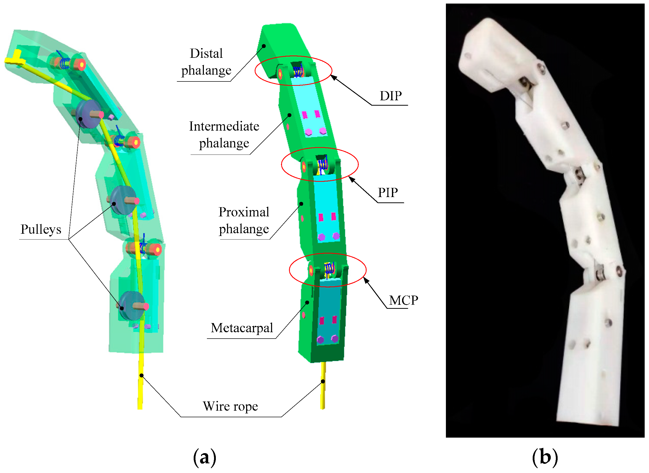
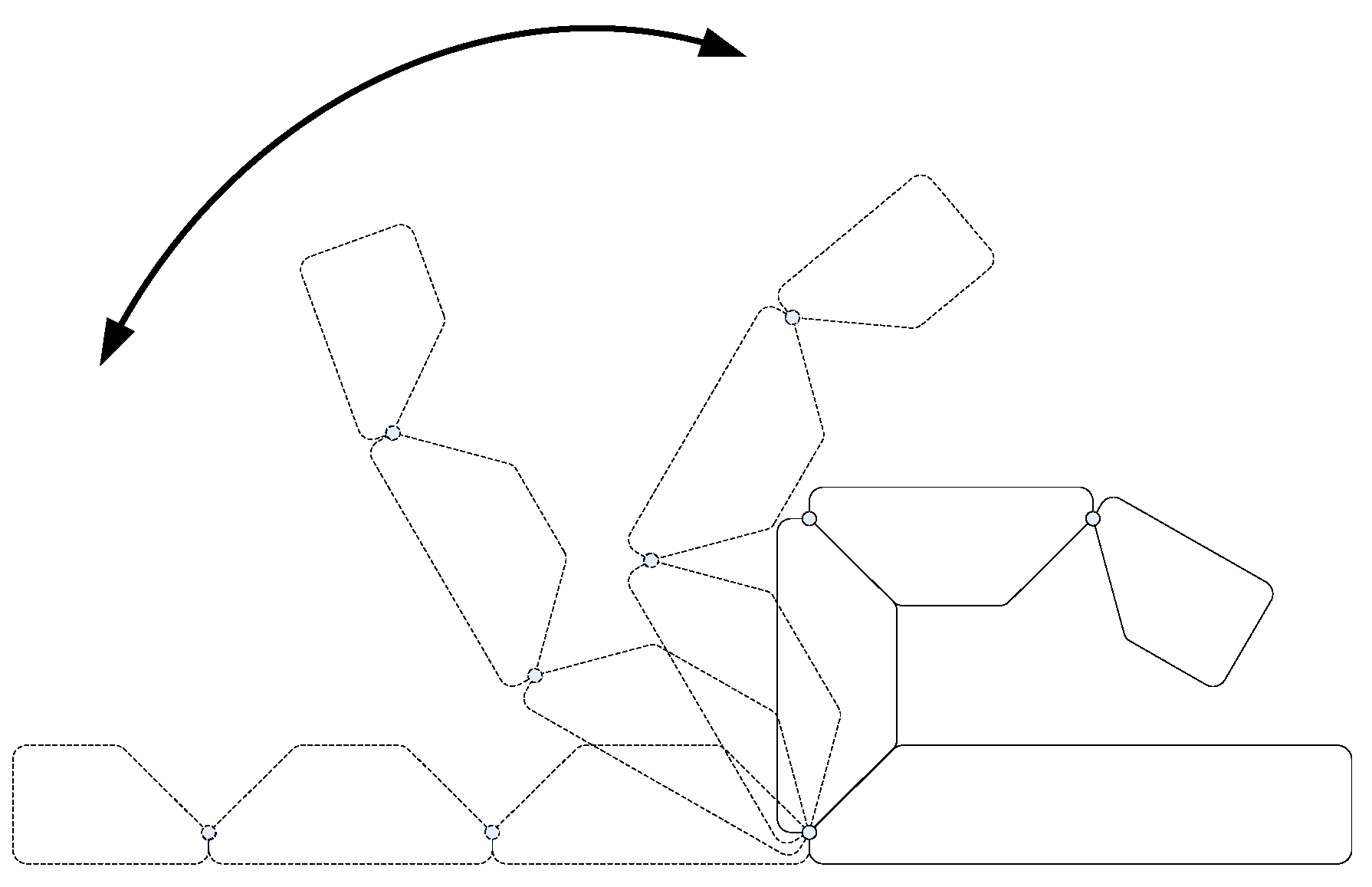
2.1. Design of the Adaptive Finger Structure

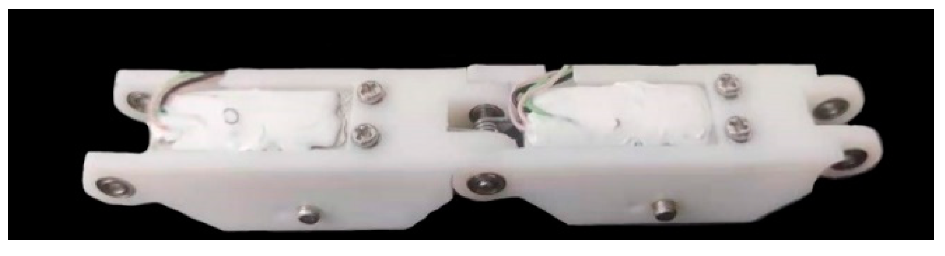
2.1.1. Prototype Design

For the human hand, except the thumb, every finger consists of three phalanges: the distal phalange, the intermediate phalange and the proximal phalange. So, we designed the finger with three phalanges and three rotatable joints. The designed finger is driven by a steering gear. There is a wire rope running through three phalanxes. One side of the wire rope is fixed on the top of the distal phalange, and the other side is connected to the swing arm of the steering gear. Therefore, the steering gear rotation drives the wire rope movement to achieve finger bending. The rotatable joint consists of a roller, a torsion spring, and four bearings. The roller passes through the four bearings and the torsion spring. In order to reduce the friction between the wire rope and the phalanges, three guide pulleys are fitted up on the middle finger bone, the proximal finger bone and the metacarpal bone. The fingers are naturally straight in this structure when there is no driving force from the wire rope. Under the driving force of the wire rope, the finger is bent. However, the finger stays straight again when the driving force disappears. In the case that the fingers do not touch the object, the three finger bones move synchronously under the traction of the wire rope. In the process of grasping the object, the movement of each phalange in the finger will not change when the finger with rigid connecting rod structure contacts with an object. As a result, when grasping an irregular object, some phalanges cannot make good contact with the object, which reduces the stability of grasping. For the finger proposed in this paper, the movement of the phalange which contacted with object will be restricted. While in front of the restricted phalanges, the phalanges that are not in contact with the object remain unchanged. It is because of this movement law that the designed finger can well adapt to objects with different shapes and carry out steady grasping. In other words, the elastic-spring finger joints between phalanges can make the maximized contact area with objects during the bending movement of the finger, since each phalange can move freely even other phalanges are restricted by the edge of object. So the adaptive situation is mainly decided by the contacting between finger and object during the grasping process. In this paper, the phalanges are fabricated using 3D printing technology. Figure 1 shows the 3-D model and prototype of the finger.

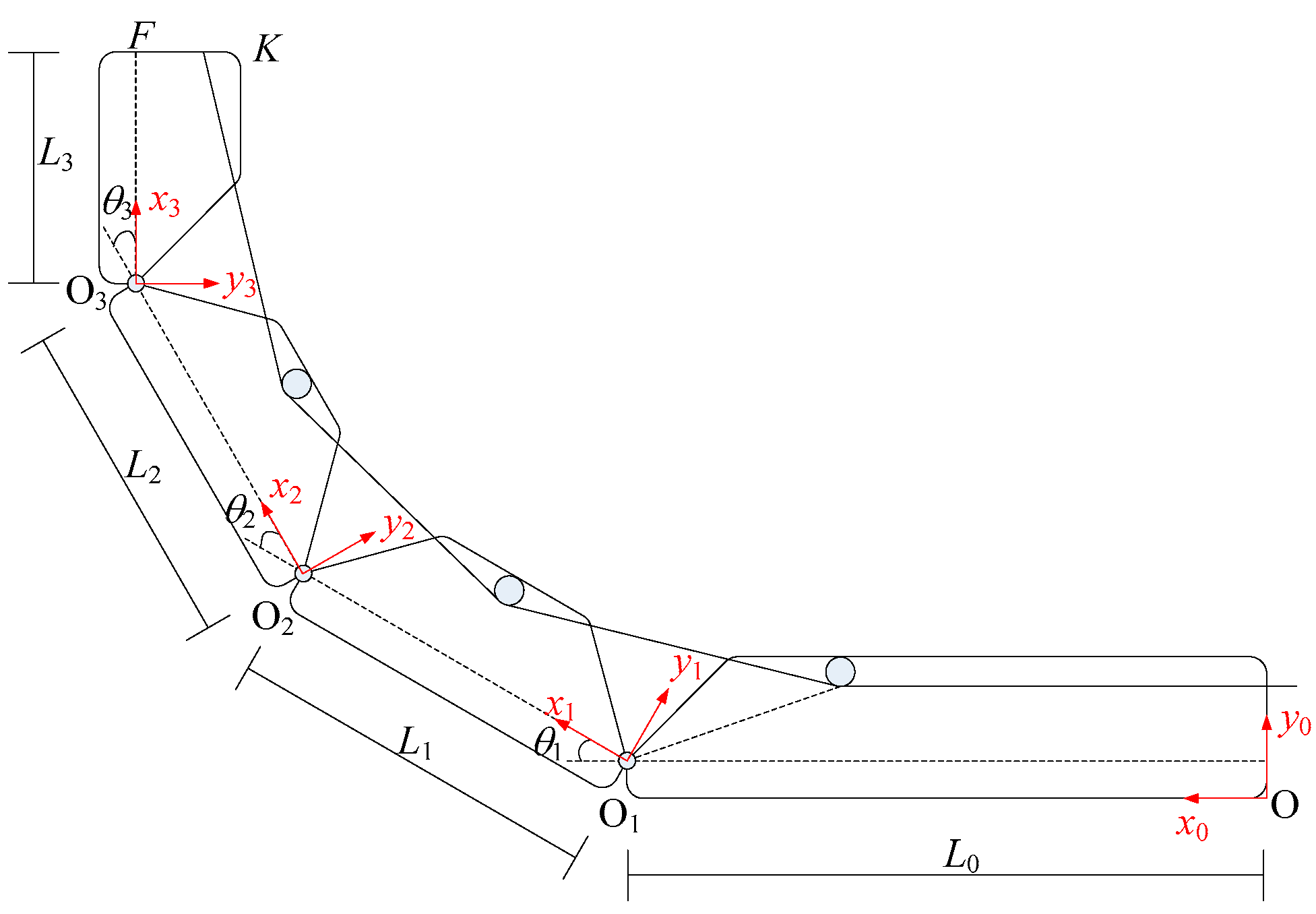
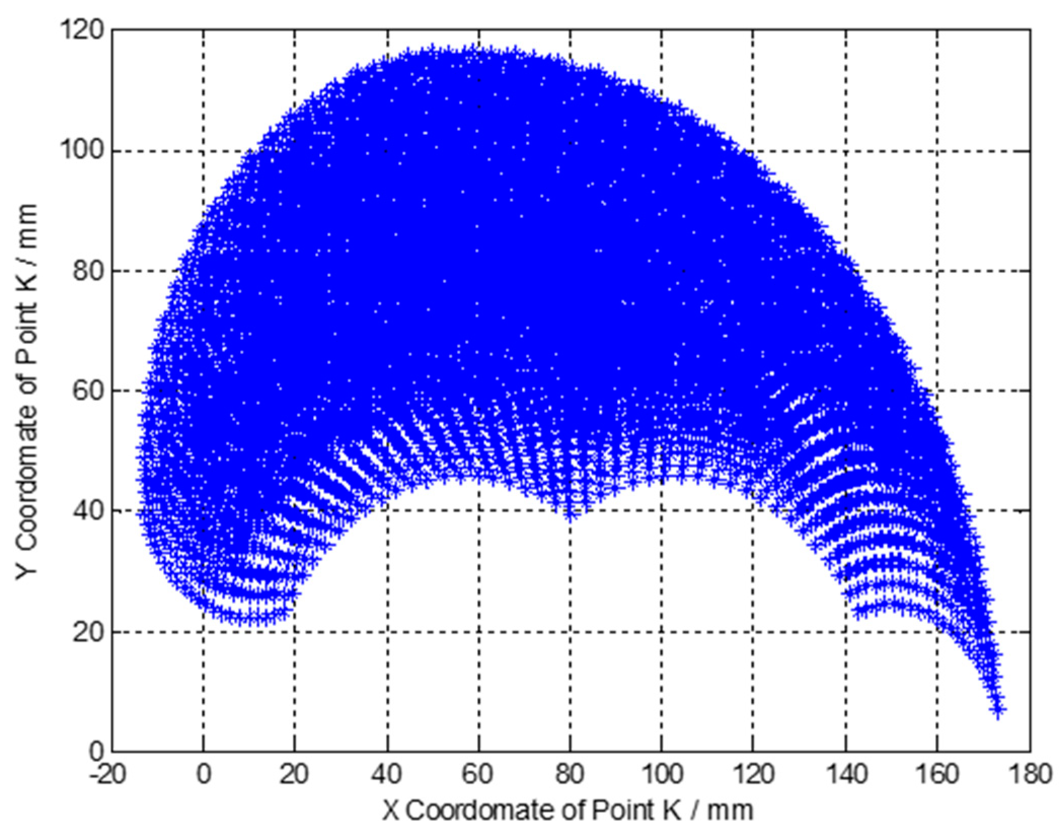
2.1.2. Forward Kinematics

Figure 2 illustrates the geometric representation. The distal interphalangeal (DIP) joint angle, proximal interphalangeal (PIP) joint angle and metacarpophalangeal (MCP) joint angle are 180°-θ3, 180°-θ2 and 180°-θ1, respectively. The length of the distal phalange, intermediate phalange, proximal phalange and metacarpal are L3, L2, L1 and L0, respectively.
The orientation and position of the finger and the fingertip are determined by the forward kinematic model and the joint angles. Here, Denavit-Hartenberg(DH) parameter approach is introduced to analyze the kinematic of the finger. Table 1 shows the DH parameters and ranges of the finger.
Based on the general form of the transformation matrix (Equation (1)) and the DH parameters (Table 1), we can achieve the transformation matrices from each phalange of the finger at its neighboring phalange as follows.
T i i 1 = cos θ i sin θ i 0 a i 1 sin θ i cos α i 1 cos θ i cos α i 1 sin α i 1 d i sin α i 1 sin θ i sin α i 1 cos θ i sin α i 1 cos α i 1 d i cos α i 1 0 0 0 1
T 1 0 = cos θ 1 sin θ 1 0 L 0 sin θ 1 cos θ 1 0 0 0 0 1 0 0 0 0 1
T 2 1 = cos θ 2 sin θ 2 0 L 1 sin θ 2 cos θ 2 0 0 0 0 1 0 0 0 0 1
T 3 2 = cos θ 3 sin θ 3 0 L 2 sin θ 3 cos θ 3 0 0 0 0 1 0 0 0 0 1
The overall transformation matrix can be yielded by multiplying these three individual matrices.
T 3 0 = T 1 0 T 2 1 T 3 2 = cos ( θ 1 + θ 2 + θ 3 ) sin ( θ 1 + θ 2 + θ 3 ) 0 L 0 + L 1 cos θ 1 + L 2 cos ( θ 1 + θ 2 ) sin ( θ 1 + θ 2 + θ 3 ) cos ( θ 1 + θ 2 + θ 3 ) 0 L 1 sin θ 1 + L 2 sin ( θ 1 + θ 2 ) 0 0 1 0 0 0 0 1
By considering the point K as the fingertip. In Figure 2, the position of the fingertip in the coordinate system of x3y3z3 is as follows.
p x 3 y 3 z 3 = L 3 F K 0
The position of the fingertip with respect to the coordinate system of x0y0z0 can be expressed as follows.
K x 0 y 0 z 0 = T 3 0 L 3 F K 0 1 = L 0 + L 1 cos θ 1 + L 2 cos ( θ 1 + θ 2 ) + L 3 cos ( θ 1 + θ 2 + θ 3 ) F K sin ( θ 1 + θ 2 + θ 3 ) L 1 sin θ 1 + L 2 sin ( θ 1 + θ 2 ) + L 3 sin ( θ 1 + θ 2 + θ 3 ) + F K cos ( θ 1 + θ 2 + θ 3 ) 0 1
Based on Equation (7) and the parameters of the finger shown in Table 1, we obtained the distribution of the X and Y coordinate of the fingertip as shown in Figure 3.

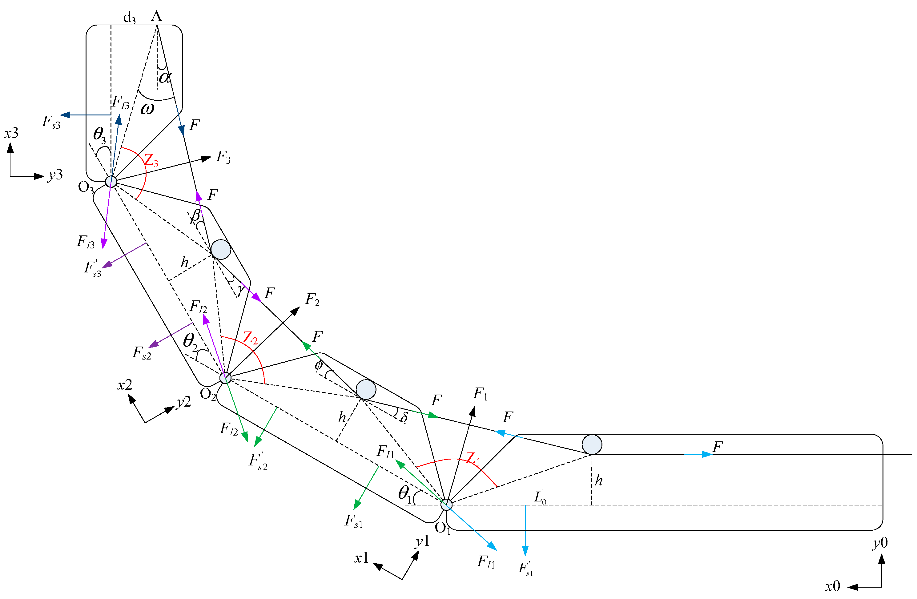
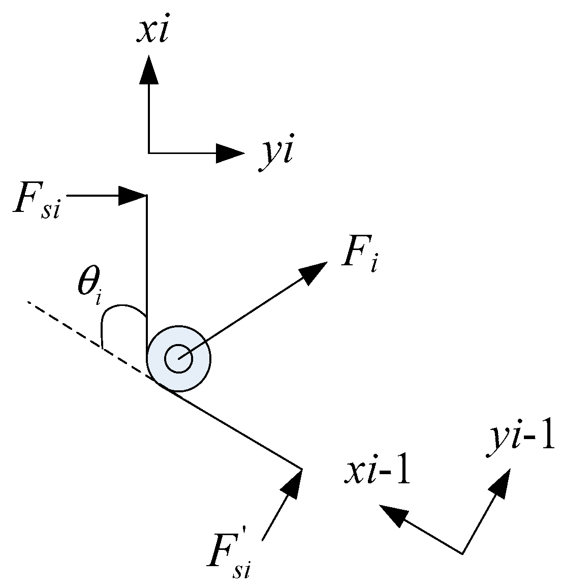
2.1.3. Mechanical Analysis

Figure 4 shows the diagram when the finger bended. The different colored arrows represent the forces exerted on the different phalanges. F is the driving force on the wire rope. FIi is the force between the ith and (I − 1)th phalanges. Fsi and Fsi are the force exerted by torsion spring on the ith and (I − 1)th phalanges, respectively. Fi is the force of torsion spring on the shaft. Since the shaft is connected to the two adjacent phalanges by four bearings, Fi is divided equally between the two phalanges. That is to say, half of Fi is applied to the ith phalange, and the other half is applied to the (I − 1)th phalange. The relevant mechanical dimension parameters in the figure are shown in Table 2.
For the distal phalange, we can get the equilibrium equations of force and moment balance equation as follows.
F I 3 ( x 3 ) + 1 2 F 3 ( x 3 ) = F cos α F I 3 ( y 3 ) + 1 2 F 3 ( y 3 ) + F sin α = F s 3 b 3 F sin ω = F s 3 l 3
where, FI3(x3) and FI3(y3) are the component of FI3 in the x3 and y3 directions.
Similarly, we can obtain the force balance equation and moment balance equation on the middle phalange and proximal phalange.
F I 2 ( x 2 ) + F cos β + 1 2 F 2 ( x 2 ) = F I 3 ( x 2 ) + 1 2 F 3 ( x 2 ) + F cos γ F I 2 ( y 2 ) + 1 2 F 2 ( y 2 ) + 1 2 F 3 ( y 2 ) + F sin β + F sin γ = F I 3 ( y 2 ) + F s 3 + F s 2 F s 2 l 2 + F s 3 ( L l 3 ) + F I 3 ( y 2 ) L + d F cos β = 1 2 F 3 ( y 2 ) L + d F cos γ + L 2 F sin β + L 2 F sin γ
F I 1 ( x 1 ) + F cos ϕ + 1 2 F 1 ( x 1 ) = F I 2 ( x 1 ) + 1 2 F 2 ( x 1 ) + F cos δ F I 1 ( y 1 ) + 1 2 F 1 ( y 1 ) + 1 2 F 2 ( y 1 ) + F sin δ + F sin ϕ = F I 2 ( y 1 ) + F s 2 + F s 1 F s 1 l 1 + F s 2 ( L l 2 ) + F I 2 ( y 2 ) L + d F cos ϕ = 1 2 F 2 ( y 2 ) L + d F cos δ + L 2 F sin ϕ + L 2 F sin δ
As shown in Figure 5, according to Hooke’s law, the force of Fsi and Fsi can be expressed as follows.
F s i = k i θ i l i i = 1 , 2 , 3 F s i = k i θ i l i i = 1 , 2 , 3
where ki is the stiffness of the torsion spring, li and li are the length torsion spring’s legs, and θi is the bended angle between two phalanges.
By force analysis of the torsion spring, we can know that Fi is the resultant force of Fsi and Fsi. The decomposition of Fi in coordinate xioiyi and xi−1oi−1yi−1 can be expressed as follows.
F i ( x i ) = F s i sin θ i F i ( y i ) = F s i + F s i cos θ i
F i ( x i 1 ) = F s i sin θ i F i ( y i 1 ) = F s i + F s i cos θ i
For the interaction, FIi, between the two phalanges, we can get the following relationship.
F I i ( y i ) sin θ i + F I i ( x i ) cos θ i = F I i ( x i 1 ) F I i ( y i ) cos θ i F I i ( x i ) sin θ i = F I i ( y i 1 )
where, FIi(xi) and FIi(yi) are the components of FIi in the xi and yi directions, and FIi(xi−1) and FIi(yi−1) are the components of FIi in the xi−1 and yi-1 directions.
For the angle between the wire rope and phalanges, α, β, γ, δ and θ, we can obtain the following relationship according to the law of sines.
α = arcsin b 3 c 3 sin z 3 arctan d 3 L 1 β = arcsin a 3 c 3 sin z 3 arctan h L 2 γ = arcsin b 2 c 2 sin z 2 arctan h L 3 ϕ = arcsin a 2 c 2 sin z 2 arctan h L 2 δ = arcsin b 1 c 1 sin z 1 arctan h L 3
where,
z 3 = 180 arctan d 3 L 3 arctan h 1 2 L 2 θ 3 z 2 = 180 arctan h 1 2 L 2 arctan h 1 2 L 1 θ 2 z 1 = 180 arctan h 1 2 L 1 arctan h L 0 θ 1
The following relation can be obtained by connecting the above Equations (8)–(16).
{ k 1 θ 1 = L 1 2 k 2 θ 2 l 2 + k 2 θ 2 l 2 cos θ 2 F I 2 _ x 2 sin θ 2 + F I 2 _ y 2 cos θ 2 L 1 + L 1 2 F sin ϕ + F sin δ + F cos ϕ F cos δ h 1 2 k 2 θ 2 l 2 L 1 l 2 k 2 θ 2 = L 2 2 k 3 θ 3 l 3 + k 3 θ 3 l 3 cos θ 3 + L 2 2 F sin β + F sin γ + ( F cos γ F cos β ) h F I 3 _ x 3 sin θ 3 + F I 3 _ y 3 cos θ 3 L 2 k 3 θ 3 l 3 L 2 l 3 k 3 θ 3 = F b 3 a 3 c 3 sin z 3 F I 1 _ x 1 = F cos ϕ + F I 2 _ x 2 cos θ 2 F I 2 _ y 2 sin θ 2 + 1 2 k 2 θ 2 l 2 sin θ 2 1 2 k 1 θ 1 l 1 sin θ 1 F cos δ F I 1 _ y 1 = 1 2 k 2 θ 2 l 2 + 1 2 k 2 θ 1 l 1 1 2 k 2 θ 2 l 2 cos θ 2 F sin δ F sin ϕ + F I 2 _ x 2 sin θ 2 + F I 2 _ y 2 sin θ 2 1 2 k 1 θ 1 l 1 cos θ 1 F I 2 _ x 2 = F cos γ + 1 2 k 3 θ 3 l 3 sin θ 3 + F I 3 _ x 3 cos θ 3 1 2 k 2 θ 2 l 2 sin θ 2 F cos β F I 3 _ y 3 sin θ 3 F I 2 _ y 2 = 1 2 k 3 θ 3 l 3 + 1 2 k 2 θ 2 l 2 + F I 3 _ x 3 sin θ 3 + F I 3 _ y 3 cos θ 3 F sin γ F cos β 1 2 k 2 θ 2 l 2 1 2 k 2 θ 2 l 2 cos θ 2 1 2 k 3 θ 3 l 3 cos θ 3 F I 3 _ x 3 = F cos α 1 2 k 3 θ 3 l 3 sin θ 3 F I 3 _ y 3 = 1 2 k 3 θ 3 l 3 - k 3 θ 3 l 3 cos θ 3 - F sin α
In the structure of the finger proposed in this paper, the torsion spring embedded in the finger joint is an important factor affecting the motion law of the bionic finger. Torsion springs with different stiffness coefficient lead to different motion characteristic of the finger. And the following three types of movements may occur in the procedure of the finger grasping an object.
One case is that the small stiffness coefficient of torsion spring implanted in DIP joint leads to the asynchronous movement of each joint of the bionic finger. And the DIP joint bends at an angle greater than the MCP and PIP joints. The movement process is shown in Figure 6a. The other case is that the small stiffness coefficient of torsion spring implanted in PIP joint also leads to the asynchronous movement of the finger. In extreme cases, the proximal finger joint hardly moves until it touches the object, while the distal finger joint can only bend relatively slightly. The movement process is shown in Figure 6b. There is another case that the small stiffness coefficient of torsion spring implanted in MCP joint will cause both PIP and DIP joints to have almost no relative bending movement during the whole movement process. In this case, the three phalanges of the bionic finger seem to be equivalent to one phalange, which makes the bionic hand lack dexterity.
Obviously, the finger motion laws discussed above are not suitable for grasping objects. However, if the stiffness coefficient of the torsion spring at each joint of the finger is selected properly, the bionic finger can achieve an adaptive motion rule similar to that of a human hand, which makes the bionic finger have good grasping performance. This finger motion schematic is shown in Figure 6c. In this case, the bionic finger can adapt to objects of different shapes and sizes to achieve stable grasping.
During natural movement, the movement of the finger is similar to that shown in Figure 6c. Each joint of the finger moves synchronously and the rotation angle of each joint satisfies a certain movement law [13]. In order to simplify the design of bionic finger structure parameters and realize the adaptive motion as shown in Figure 6c, the motion relationship of joint rotation is simplified here. As shown in Figure 7, the rotation angles of PIP, DIP and MCP joints approximately satisfy the relationship of 3:3:1. Meanwhile, it is considered that the maximum bending angle of each joint in the finger designed in this paper is 90°. Therefore, in the selection of spring parameters θ1 = θ2 = 3θ3 = 90° is taken as a constraint.
In this paper, the K1 and K2 parameters are obtained as follows on the premise of choosing K3 = 2.8 N·mm/degree based on the limiting relation of rotation angles of the three joints mentioned above.
K 1 = 1.5531   N · mm / degree K 2 = 1.4119   N · mm / degree
In practice, we choose torsion springs with similar stiffness coefficients in the market. The selected torsion springs with the stiffness are as follows.
K 1 = 1.605   N · mm / degree K 2 = 1.375   N · mm / degree

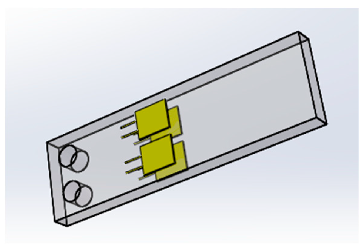
2.2. Mechanical-Sensor Integrated Finger Joint

The capacity of information perception is important for a dexterous hand. There are many kinds of thin-film force or tactile sensors that can be easily assembled on the surface of a bionic finger to capture information such as grasp force. However, joint angles are much more difficult to obtain because there is usually not enough space on the finger for angle sensors. This subsection describes in detail the design of a mechanical sensor-integrated finger joint, which mainly consists of two parts: analysis of finger joint structure and signal measurement circuit. The design is to achieve accurate measurement of the bending angle of each joint when grasping an object.

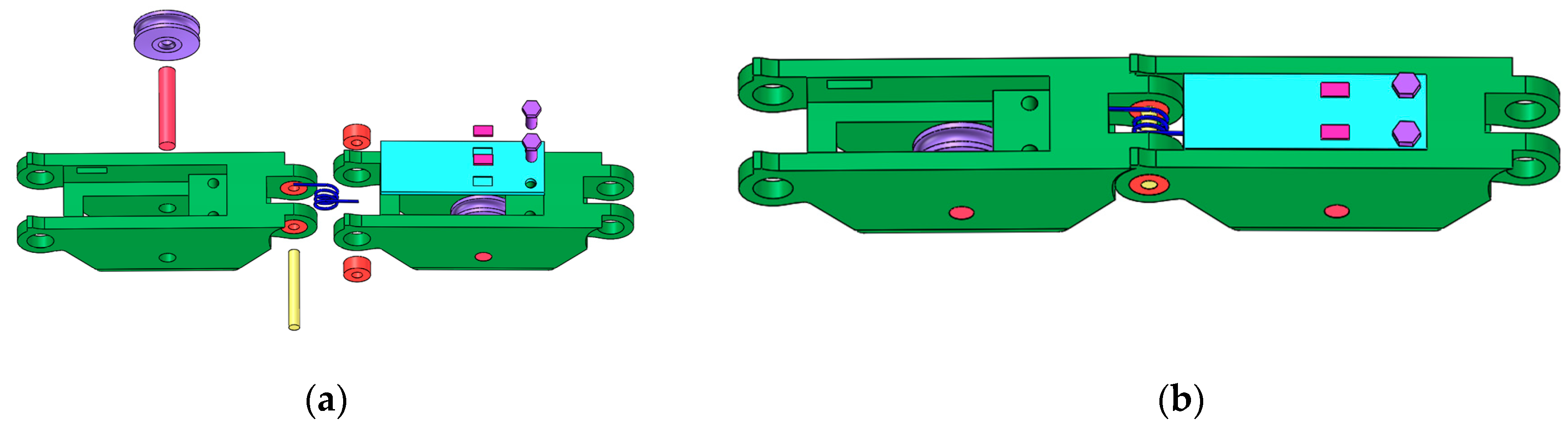
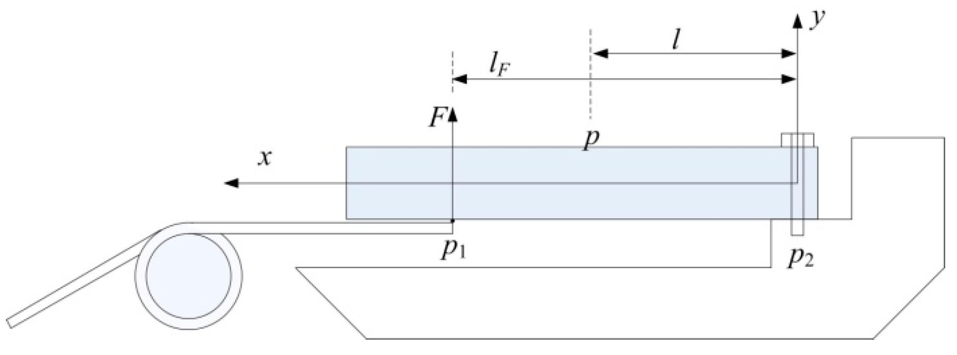
2.2.1. Analysis of Finger Joint Structure

Figure 8 shows a designed finger joint. The rotatable joint consists of a roller, a torsion spring and four bearings. The roller passes through four bearings, a torsion spring and two phalanges. One leg of the torsion spring is fastened to one phalange, and the other leg is pressed by a small aluminum plate. The aluminum plate is fastened to the other phalange with two screws.
Take the joint between proximal phalange and metacarpal for example. The torsion spring will output a torque when there is an angle between the proximal phalange and metacarpal. Because two legs of the torsion spring are restricted by the aluminum plate and the phalange, the torque output from the spring will be converted to force and be applied to the aluminum plate.
The aluminum plate can be considered as a cantilever beam because one side of the aluminum plate is fixed on the metacarpal bone by two screws. A simplified assembly drawing for aluminum plates and torsion springs has been shown in Figure 9. lF is the distance between the point p1 and p2. p1 is the contact position of the torsion spring and the aluminum plate. p2 is the root of the aluminum plate.
When a finger bends, the axial strain at point p, on the surface of the aluminum plate is as follows:
ε p = 6 F E b h 2 ( l F l )
where E is the Young’s modulus of the material, l is the distance between point p and p2, b and h are the width and thickness of the cantilever beam respectively
Combining Equations (11) and (20), we can get the relationship between finger joint angle (θ) and axial strain on the surface of the aluminum plate ( ε P ) as follows:
θ = ε P E b h 2 6 ( l F l ) k l s
Where θ and ε P are linearly related in the recoverable deformation range of the aluminum plate. In other words, as long as we can get ε P , the finger joint angle(θ) can be obtained by simple calculation.

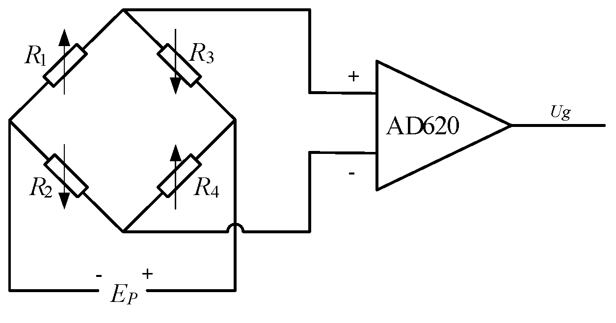
2.2.2. Signal Measurement Circuit

A strain gauge is used to measure the axial strain on the surface of the aluminum plate in this paper. Within the limit of the strain gauge, the relationship between the axial strain and the variation of the resistance is linear.
The maximum bending angle of the designed finger in this paper is 90°. Therefore, the maximum axial strain on the surface of the aluminum plate can be described as follows.
ε P _ max = k l s θ max 6 ( l F l ) b h 2 E = 540 k l s ( l F l ) b h 2 E
Based on the above analysis, the strain gauges with the parameters shown in Table 3 are used to achieve the measurement of the axial strain on the surface of the aluminum plate.
As shown in Figure 10, four strain gauges were pasted on the upper and the lower surface of the aluminum plate respectively. Among of them, two strain gauges sg2 and sg3, were pasted on the upper surface of the aluminum plate, and the other two strain gauges, sg1 and sg4, were pasted on the lower surface. When the fingers are bent, the force exerted by the torsion spring on the aluminum plate causes deformation of the plate. And the deformation of the aluminum plate will likewise cause the deformation of the strain gauge. Since the extensional deformation and compressive deformation lead to the increase and decrease of strain gauge resistance respectively, the finger bending leads to the increase of resistance of sg1 and sg4 and the decrease of resistance of sg2 and sg3. And since sg2, sg3 and sg1, sg4 are distributed symmetrically, the resistance variations of sg1, sg2, sg3 and sg4 are the same.
As shown in Figure 11, the strain gauges, sg1, sg2, sg3 and sg4, are plugged into the circuit. Amplifier based on AD620 is used to amplify the output signal of the Wheatstone bridge. Under the assumption that sg1 and sg3 are pasted on the surface of the cantilevered beam symmetrically and R1 = R2 = R3 = R4, we can get the output of the circuit:
U g = A Δ R 1 R 1 E P
where EP is the value of the supply power, △R1 is resistance variation of the four strain gauges, A is the amplification.
The relationship between strain and relative variation of the resistance, Δ R R = K ε , is linear within a large range. The relationship between the circuit output and the strain of the strain gauge can be expressed as follows.
θ = F k l s = E b h 2 6 ( l F l ) A E P K k l s U
where K is the sensitivity factor of the strain gauge.
There are three finger joints with the same structure in the designed finger. Therefore, three measurement circuits are designed as shown in Figure 11.
Figure 12 shows the phalanges equipped with aluminum plates.

3. Experiments and Results

To evaluate the designed finger, joint angle measurement experiment, movement law evaluation experiment and objects’ grasping experiment are conducted.

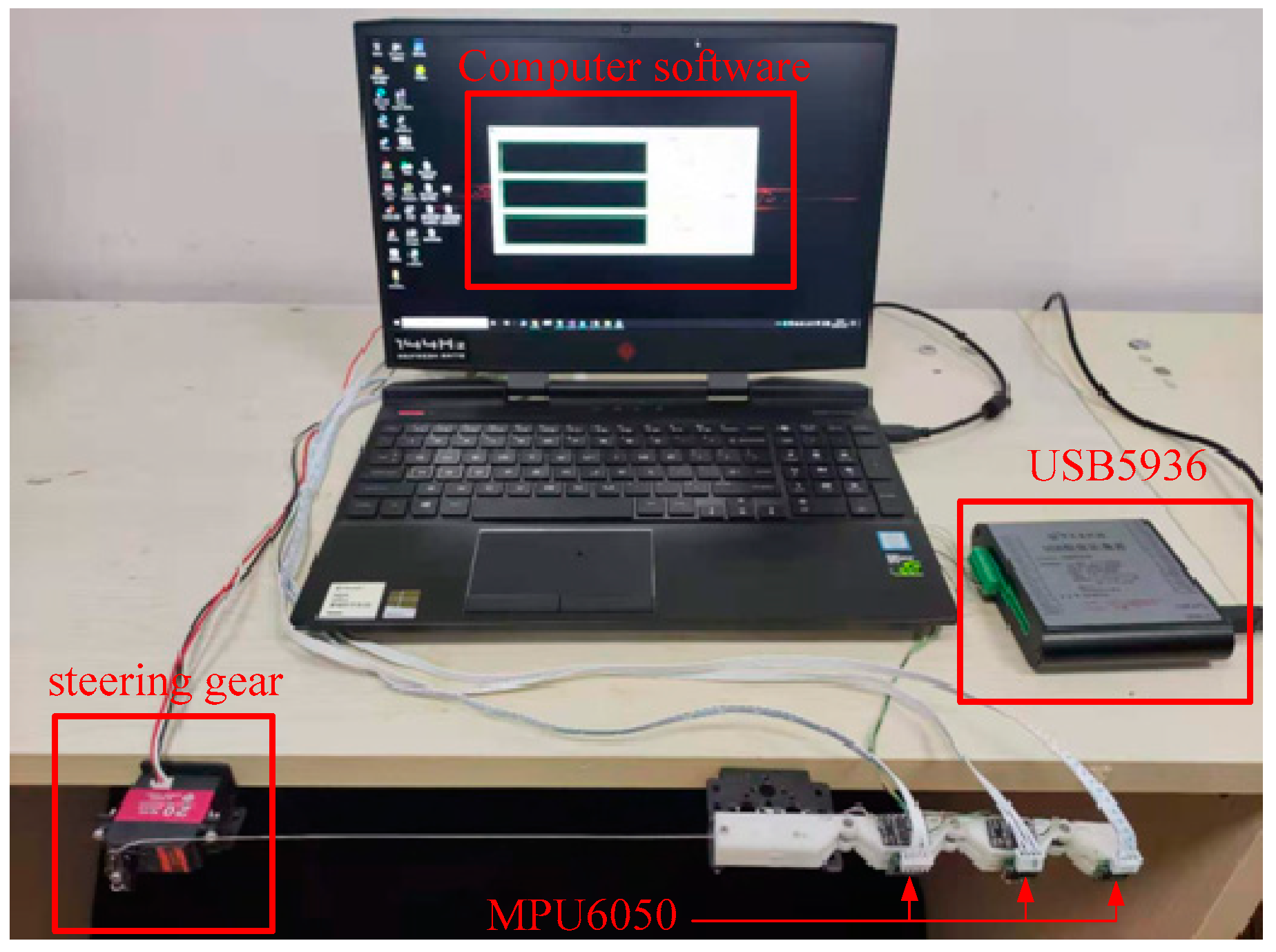
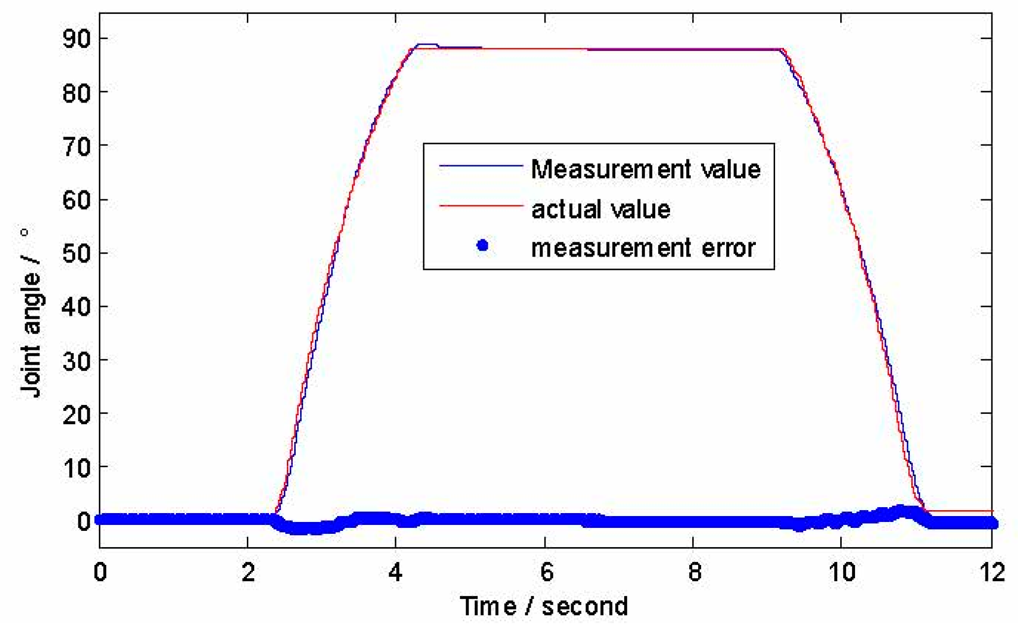
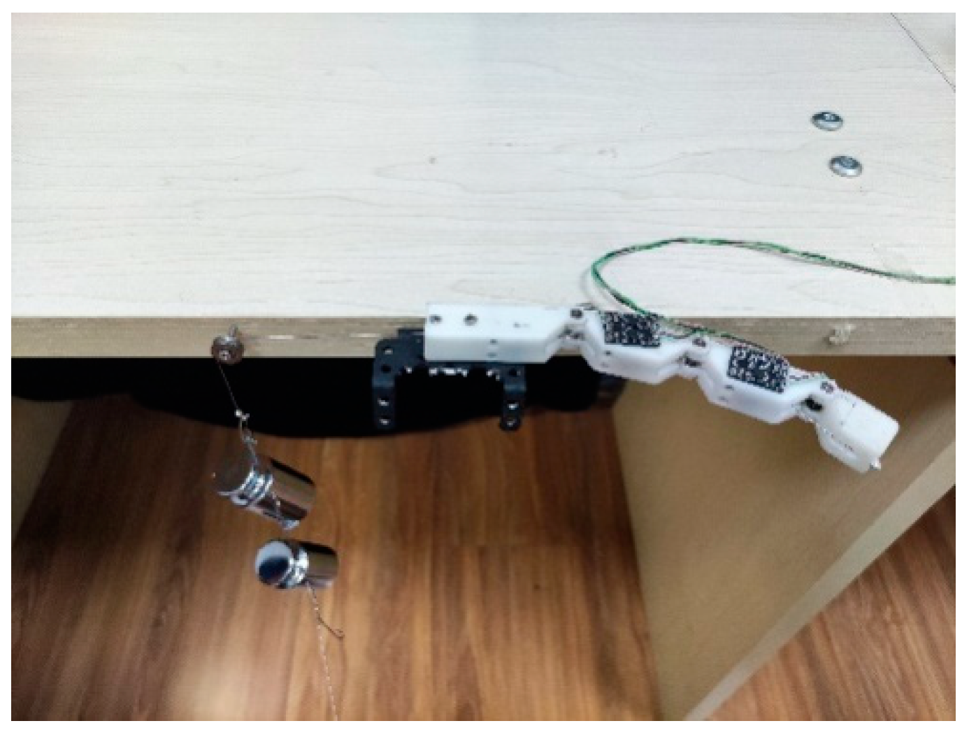
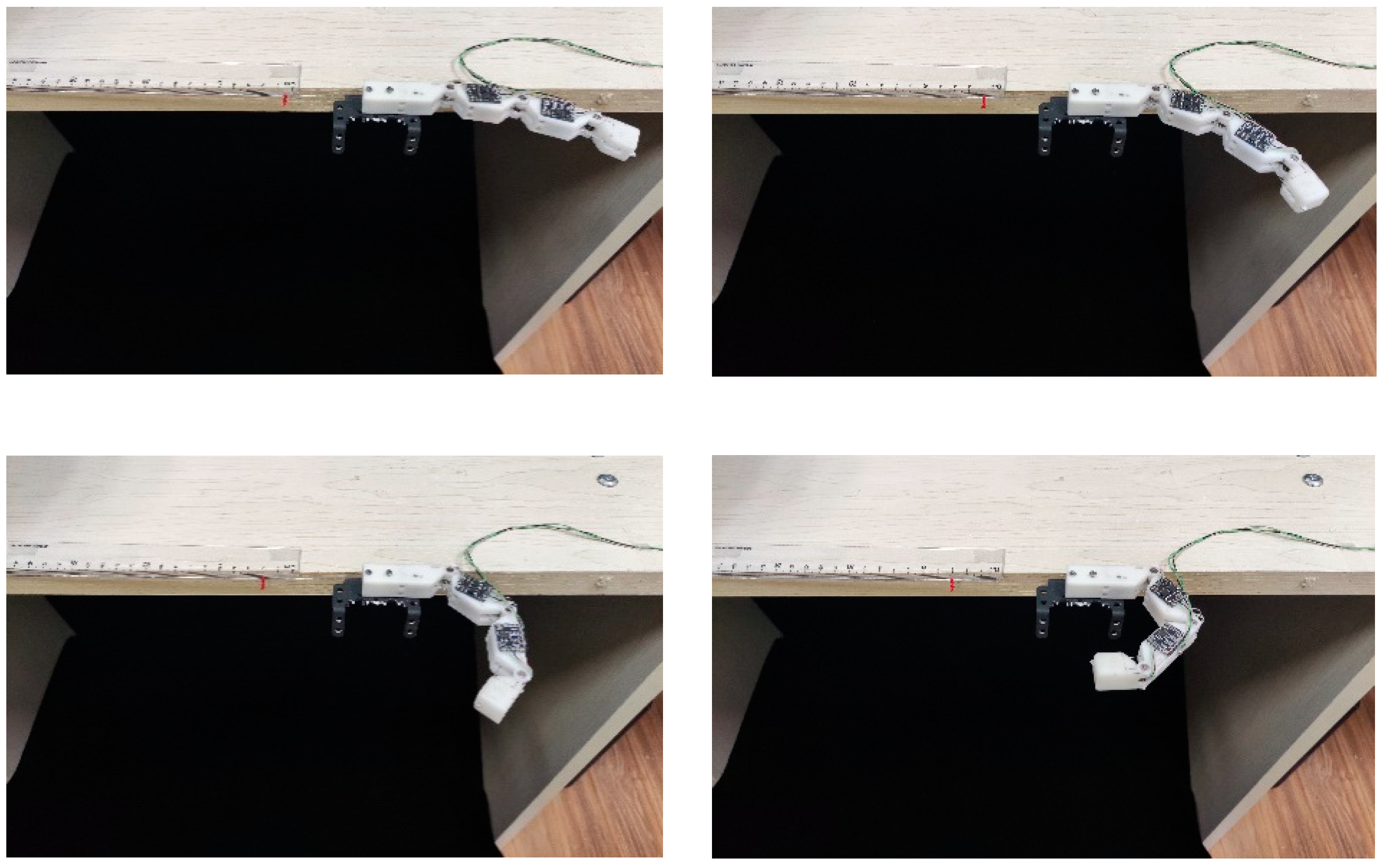
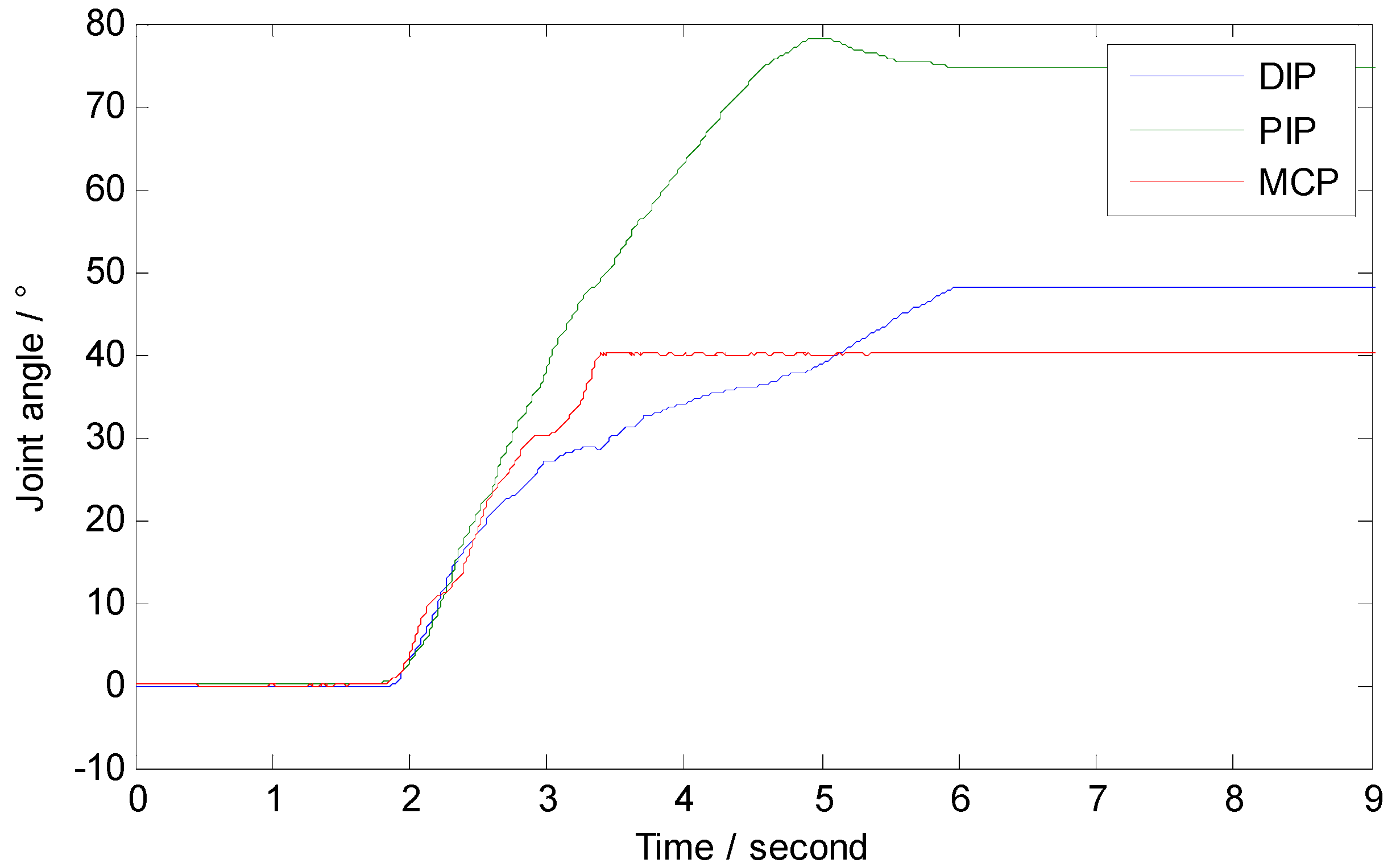
3.1. Joint Angle Measurement Experiment

The experimental setup consists of a finger, a steering gear, three gyroscopes, a data acquisition card and computer software.
As shown in Figure 13, a finger and a steering gear are fixed horizontally on the edge of the table. The wire rope is fixed to the swing arm of the steering gear. Finger bending can be realized by controlling the swinging of the steering gear. Three six-axis gyroscopes based on MPU6050 are employed to measure angles of the finger joints. The gyroscopes are pasted on the surface of the phalanges. The gyroscope outputs the rotation angle in real time at a speed of 100Hz. The dynamic measurement precision is 0.1°. A data acquisition card (USB5936) is employed to capture the signals output from the strain gauge measurement circuits. And the digital signals are sent to computer via USB. Computer software based on MFC framework is developed to display the signals and record the data.
Taking MCP angle measurement for example, the steering gear is rotated so that the proximal phalange gradually bends from 0° to 90°, and then gradually recovers from 90° to 0°. At the same time, the signal output from the gyroscope is synchronously recorded with the strain gauge measurement circuit. Figure 14 shows experimental results of the MCP angle measurement. The RMS of measurement errors of the DIP, PIP and MCP are 0.36°, 0.59° and 0.32°, respectively.

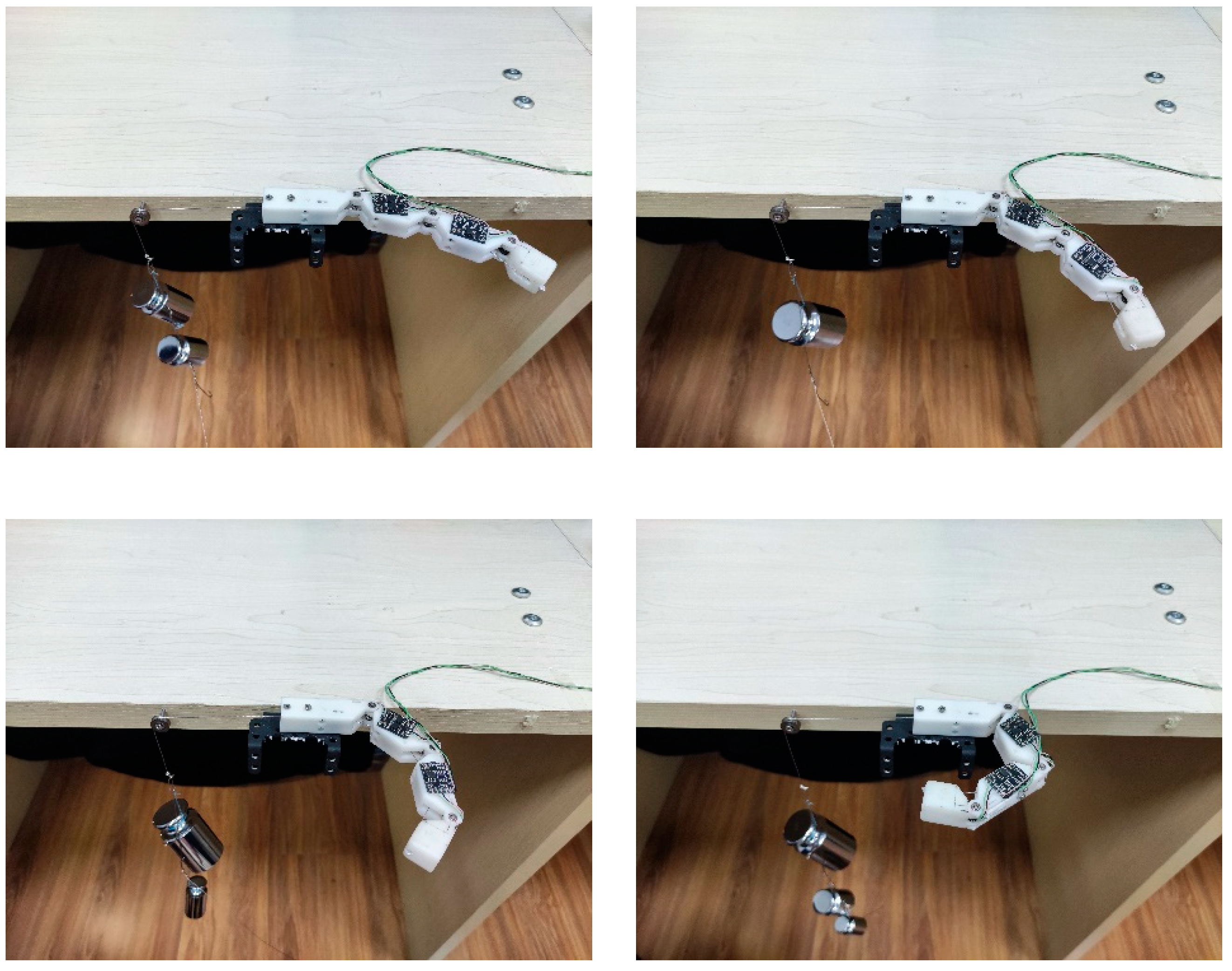
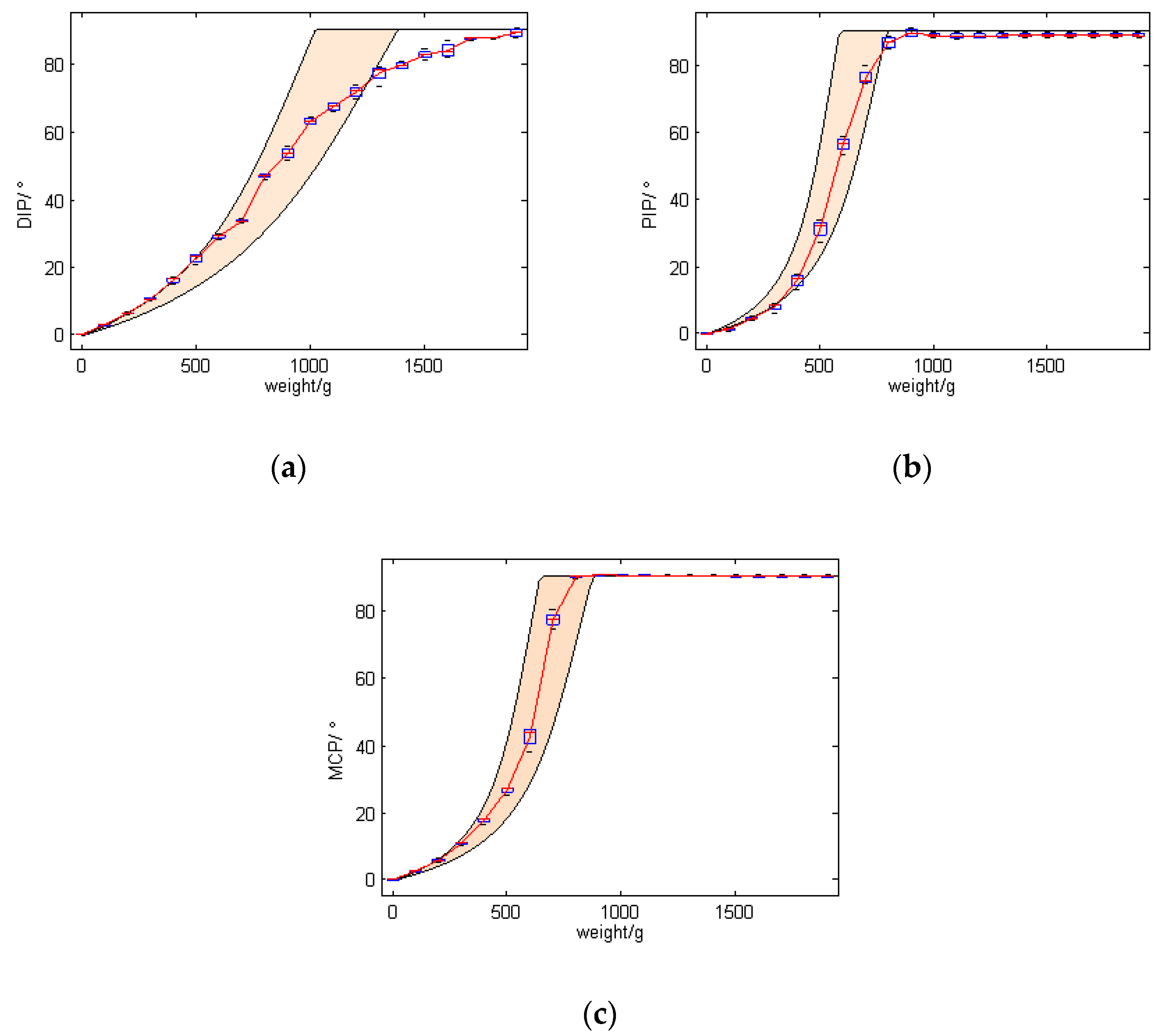
3.2. Evaluating the Relationship between Driving Force and Finger Bending Angle

Figure 15 shows an image of the experiment, where the finger is fixed to the side of the table and a weight draws the rope through a pulley to rotate the finger joints.
In this experiment, 18 weights from 100 g to 1800 g with increments of 100 g were used to test the relationship between driving force and finger bending angle for 4 times. Figure 16 shows the movement of the finger as the driving force gradually in-creases, and Figure 17 shows the bending angles of the finger joints with different driving forces. The bending angles of PIP and MCP joints are basically consistent throughout the movement. For the weights from 100 g to 800 g, the angles of all finger joints increase with increasing driving force. It basically satisfies the relationship θ1 = θ2 = 3θ3. The angles of PIP and MCP reached a maximum bending angle of 90° when the driving force was around 800 g. Consequently, from 800 g to 1800 g, the angles of PIP and MCP remained the same, while the angle of the DIP joint increased as the driving force increased. These experimental results have an important role in the con-trol of the finger in a later stage.
Considering the spring stiffness coefficient with ±15% error, the distribution area of the joints’ angle on different driving force is fulfilled with peach puff as shown in Figure 17. As can be seen from the figure, bending angles of the finger joints conforms to the design expectation.

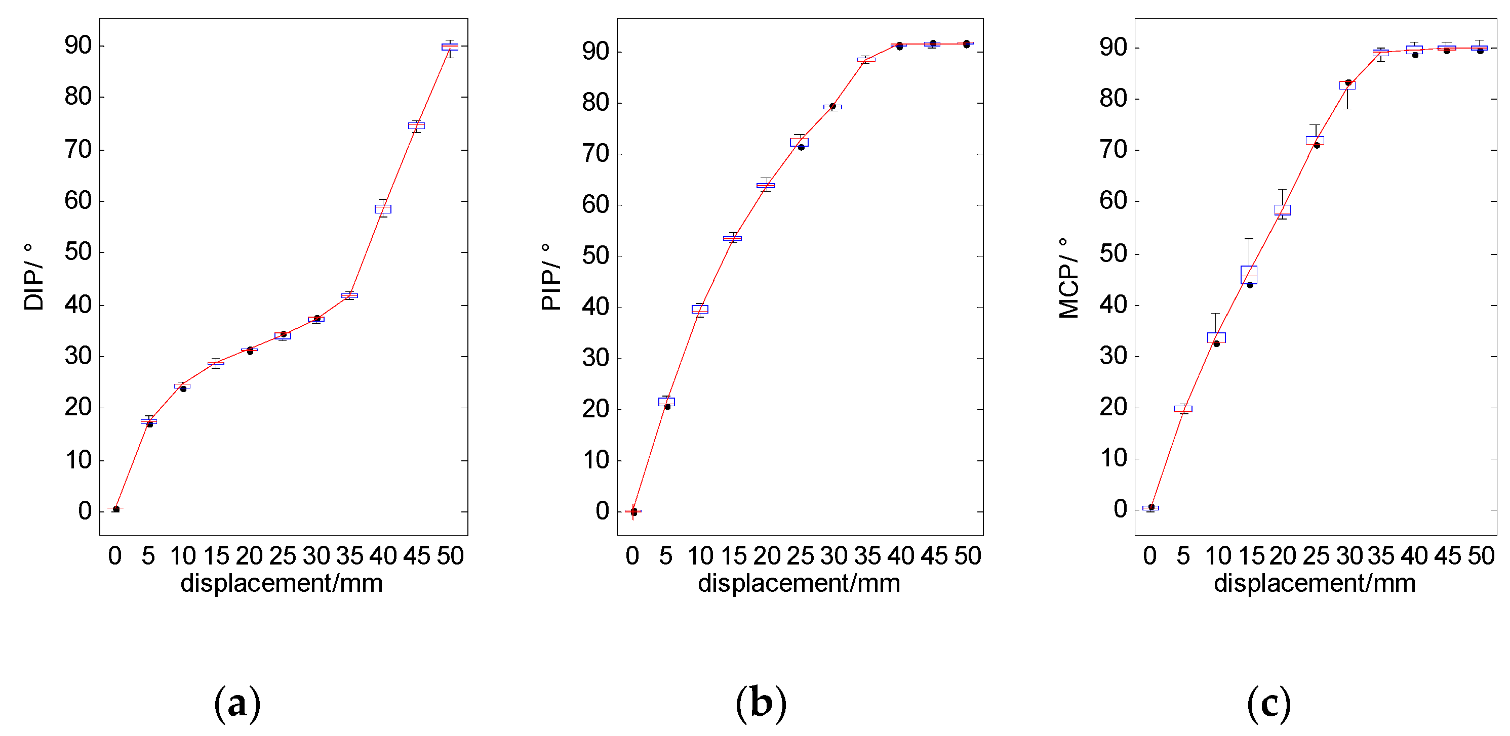
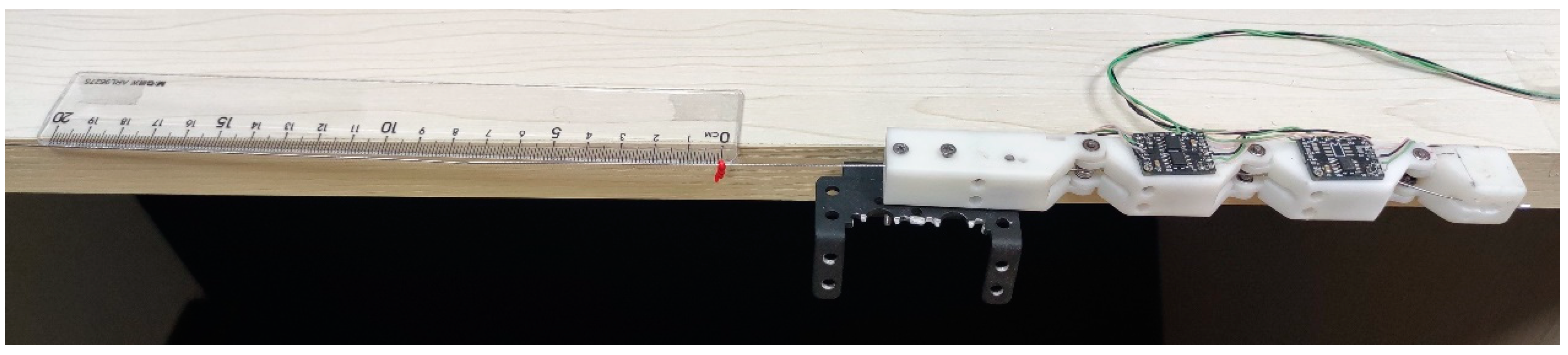
3.3. Evaluating the Relationship between Displacement of the Driving Cable and Finger Joints’ Angle

As in the previous experiment, the finger is fixed to the side of the table. A red light pointer is tied to the wire rope. Along with the ruler placed on the edge of the table, the displacement of the wire rope can be displayed. The image of the experiment is shown in Figure 18.
We measured the joint angle of the finger with increments of 5 mm within the displacement range from 0 to 50 mm. Figure 19 shows a movement of the finger as the displacement of the driving cable gradually increases. And Figure 20 shows the angle of the finger joints under different displacement of the driving cable.
For the displacement from 0 mm to 35 mm, the angles of all finger joints increase with the increase of driving force. The angles of PIP and MCP reach a maximum bending angle of 90° when the driving force is around 35 mm. Consequently, from 35 mm to 50 mm, the angle of DIP joint increases as the driving force increases.
The results of this experiment also showed that the motion of the fingers was consistent with the design expectation.

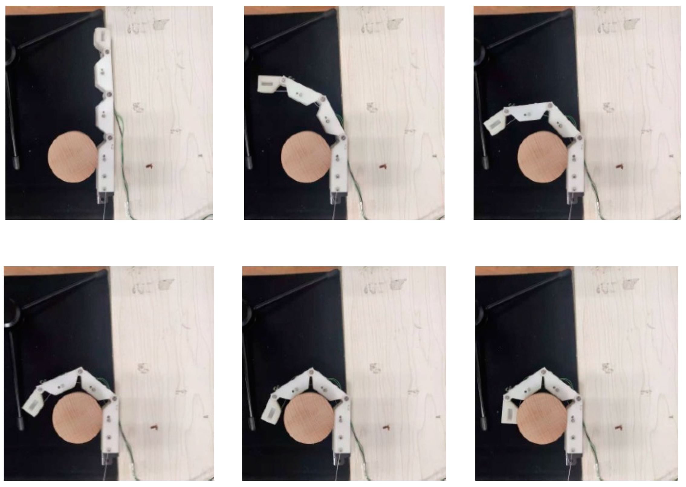
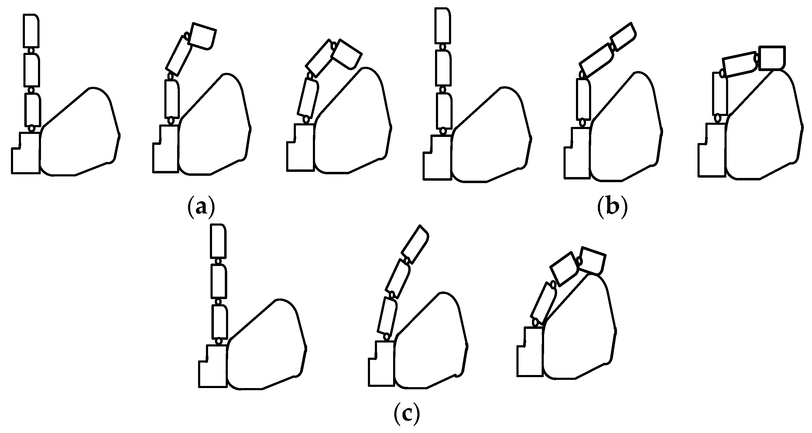
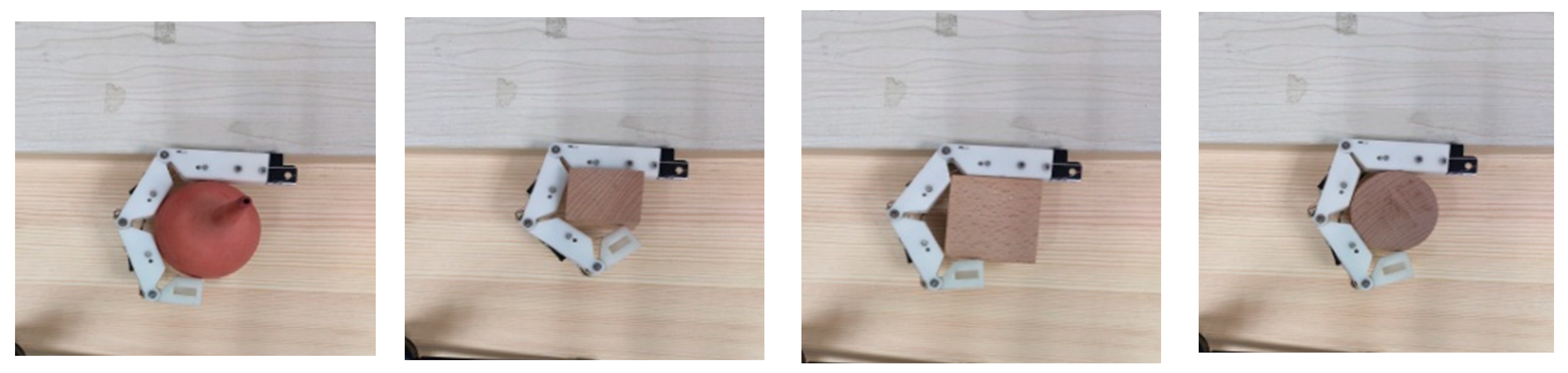
3.4. Objects’ Grasping Experiment

To verify that the designed fingers can adapt to objects of different shapes and can grasp them, four objects with different shapes, spherical, cuboid, cube, and cylinder, were selected for the experiment. Take the grasping of a cylinder for example. As shown in Figure 21, when the finger was in the state of unbending, the cylinder was place on the inside of the finger and then the finger was controlled to gradually bend and fully grasp and hold the cylinder through the steering gear. The angles of the finger joints during this process are shown in Figure 22. In the experiment, the proximal phalange contacted the cylinder first, followed by the intermediate phalange and finally the distal phalange. The results in Figure 22 show that, when the proximal phalange is in contact with the cylinder, the angle of the MCP hardly changes because movement of the phalange is restricted by the cylinder. The movements of the distal phalange and intermediate phalange are the same as that of the proximal phalange. Because of this movement law, the designed finger can adapt to objects with different shapes. Figure 23 shows stable grasping of objects with different shapes.

4. Conclusions

In order to achieve dexterous manipulation of a robot hand, an adaptive finger with joint angle measurement capability is proposed in this paper. The proposed finger has three joints. The mechanical composition of the designed finger is described in detail. Forward kinematics is conducted to analyze the distribution of the fingertip. Moreover, on the basis of force analysis of each phalanx, a set of spring coefficients is selected to make the relationship among MCP, PIP and DIP approximately satisfy 3:3:1 when the finger moves in free space. In addition, the composition, the principle and the measurement circuit of the mechanical-sensor integrated finger joint are described in detail. In the experimental section, joint angle testing, movement law evaluation and objects grasping experiments are conducted to verify the designed finger. The experimental results show that the designed finger can achieve the measurement of the joint angle of the finger with the RMS of measurement errors of MCP, PIP and DIP are 0.32°, 0.59° and 0.36°, respectively. The bending angles of the finger joints conform to the design requirements when the finger moves in free space. And the objects of different shapes can be stably grasped with the designed finger.
For the next step, we will study the control strategy for the designed finger and design a hand with the finger proposed in this paper.

Author Contributions

Conceptualization, C.W. and A.S.; methodology, C.W. and D.Y.; software, F.F.; validation, Z.W. and T.S.; formal analysis, Q.C.; investigation, C.W.; resources, B.X.; data curation, Z.W. and T.S.; writing—original draft preparation, C.W.; writing—review and editing, Q.C.; visualization, Q.C.; supervision, C.W.; project administration, C.W.; funding acquisition, C.W. All authors have read and agreed to the published version of the manuscript.

Funding

This research was funded by the National Natural Science Foundation of China under Grant No. 61803201, 91648206, 61773205. Jiangsu Natural Science Foundation under Grant No. BK20170803. The China postdoctoral science foundation under Grant No. 2019M661686.

Data Availability Statement

The data presented in this study are available in article.

Conflicts of Interest

The authors declare no conflict of interest.

References

  1. Ren, Z.; Kashiri, N.; Zhou, C.; Tsagarakis, N.G. HERI II: A Robust and Flexible Robotic Hand based on Modular Finger design and Under Actuation Principles. In Proceedings of the International Conference on Intelligent Robots and Systems, Madrid, Spain, 1–5 October 2018. [Google Scholar]
  2. Ryu, W.; Choi, Y.; Choi, Y.J.; Lee, S. Development of a Lightweight Prosthetic Hand for Patients with Amputated Fingers. Appl. Sci. 2020, 10, 3536. [Google Scholar] [CrossRef]
  3. Wahit, M.A.A.; Ahmad, S.A.; Marhaban, M.H.; Wada, C.; Izhar, L.I. 3D Printed Robot Hand Structure Using Four-Bar Linkage Mechanism for Prosthetic Application. Sensors 2020, 20, 4174. [Google Scholar] [CrossRef] [PubMed]
  4. Wu, C.; Song, A.; Zhang, H.; Feng, C. A Backstepping Control Strategy for Prosthetic Hand Based on Fuzzy Observation of Stiffness. Robot 2013, 35, 686. [Google Scholar] [CrossRef]
  5. Liow, L.; Clark, A.B.; Rojas, N. OLYMPIC: A Modular, Tendon-Driven Prosthetic Hand with Novel Finger and Wrist Coupling Mechanisms. IEEE Robot. Autom. Lett. 2019, 5, 299–306. [Google Scholar] [CrossRef]
  6. Van, D.; Bongers, R.; Sluis, C. Functionality of i-LIMB and i-LIMB pulse hands: Case report. J. Rehabil. Res. Dev. 2013, 50, 1123. [Google Scholar]
  7. Dang, L.; Song, J.; Wei, Y.; Zhang, W. COSA-LET finger: A novel coupled and self-adaptive robot finger with a linear empty-trip transmission. In Proceedings of the International Conference on Advanced Robotics & Mechatronics, Hefei, China, 27–31 August 2017. [Google Scholar]
  8. Belter, J.; Segil, J.; Dollar, A.; Weir, R.F.M. Mechanical design and performance specifications of anthropomorphic prosthetic hands: A review. J. Rehabil. Res. Dev. 2013, 50, 599. [Google Scholar] [CrossRef] [PubMed]
  9. Zhang, T.; Fan, S.; Jiang, L.; Liu, H. Design and control of a multisensory five-finger prosthetic hand. In Proceedings of the World Congress on Intelligent Control and Automation (WCICA), Shenyang, China, 29 June–4 July 2014. [Google Scholar]
  10. Li, X.; Wu, L.; Lan, T. A 3D-printed Robot Hand with Three Linkage-driven Underactuated Fingers. Int. J. Autom. Comput. 2018, 15, 593–602. [Google Scholar] [CrossRef]
  11. Liu, C.; Chen, T.; Chiu, C.; Hsu, M.-C.; Chen, Y.; Pai, T.-Y.; Peng, W.-G.; Chiang, Y.-P. Optimal Design of a Soft Robotic Gripper for Grasping Unknown Objects. Soft Robot. 2018, 5, 452–465. [Google Scholar] [CrossRef]
  12. Reis, M.; Leite, A.C.; Lizarralde, F. Modeling and Control of a Multifingered Robot Hand for Object Grasping and Manipulation Tasks. In Proceedings of the 54th IEEE Conference on Decision and Control (CDC), Osaka, Japan, 15–18 December 2015. [Google Scholar]
  13. Wattanasiri, P.; Tangpornprasert, P.; Virulsri, C. Design of Multi-Grip Patterns Prosthetic Hand with Single Actuator. IEEE Trans. Neural Syst. Rehabil. Eng. 2018, 26, 1188–1198. [Google Scholar] [CrossRef] [PubMed]
  14. Cordella, F.; Gentile, C.; Zollo, L.; Barone, R.; Sacchetti, R.; Davalli, A.; Siciliano, B.; Guglielmelli, E. A force-and-slippage control strategy for a poliarticulated prosthetic hand. In Proceedings of the IEEE 2016 International Conference on Robotics & Automation, Stockholm, Sweden, 16–21 May 2016; pp. 3524–3529. [Google Scholar]
  15. Palli, G.; Vassura, G.; Scarcia, U.; Moriello, L.; Berselli, G.; Cavallo, A.; de Maria, G.; Natale, C. The DEXMART hand: Mechatronic design and experimental evaluation of synergy-based control for human-like grasping. J. Robot. Res. 2014, 33, 799–824. [Google Scholar] [CrossRef]
  16. Fourie, R.; Stopforth, R. The mechanical design of a biologically inspired prosthetic hand, the touch hand 3. In Proceedings of the IEEE 2017 Pattern Recognition Association of South Africa and Robotics and Mechatronics, Bloemfontein, South Africa, 30 November–1 December 2017; pp. 38–43. [Google Scholar]
  17. Wu, C.; Fei, F.; Xie, M.; Cao, Q.; Yang, D.; Zeng, H.; Xu, B.; Song, A. Mechanical-Sensor Integrated Finger for Prosthetic Hand. In Proceedings of the IEEE International Conference on Robotics and Biomimetics, Kuala Lumpur, Malaysia, 12–15 December 2018. [Google Scholar]
  18. Venter, J.; Mazid, A. Tactile sensor based intelligent grasping system. In Proceedings of the IEEE International Conference on Mechatronics, Churchill, Australia, 13–15 February 2017. [Google Scholar]
  19. Luberto, E.; Wu, Y.; Santaera, G.; Gabiccini, M.; Bicchi, A. Enhancing Adaptive Grasping Through a Simple Sensor-Based Reflex Mechanism. IEEE Robot. Autom. Lett. 2017, 2, 1664–1671. [Google Scholar] [CrossRef]
  20. Wookeun, P.; Kyongkwan, R.; Suin, K.; Joonbum, B. A Soft Sensor-Based Three-Dimensional (3-D) Finger Motion Measurement System. Sensors 2017, 17, 420. [Google Scholar]
  21. Othman, A.; Hamzah, N.; Hussain, Z.; Baharudin, R.; Rosli, A.D.; Ani, A.I.C. Design and development of an adjustable angle sensor based on rotary potentiometer for measuring finger flexion. In Proceedings of the IEEE International Conference on Control System, Batu Ferringhi, Malaysia, 25–27 November 2016. [Google Scholar]
  22. Hofmann, U.A.T.; Bützer, T.; Lambercy, O.; Gassert, R. Design and Evaluation of a Bowden-Cable-Based Remote Actuation System for Wearable Robotics. IEEE Robot. Autom. Lett. 2018, 3, 2101–2108. [Google Scholar] [CrossRef]
  23. Jeong, U.; Cho, K.-J. A feasibility study on tension control of Bowdencable based on a dual-wire scheme. In Proceedings of the 2017 IEEE International Conference on Robotics and Automation (ICRA), Autom, Singapore, 29 May–3 June 2017; pp. 3690–3695. [Google Scholar]
Figure 1. The 3-D model and prototype of the designed finger. (a) 3-D model of the designed finger; (b) Prototype of the designed finger.
Micromachines 12 00033 g001
Figure 2. Geometric representation of the finger model.
Micromachines 12 00033 g002
Figure 3. Distribution of the X and Y coordinate of the fingertip.
Micromachines 12 00033 g003
Figure 4. Force diagram when finger bended.
Micromachines 12 00033 g004
Figure 5. Diagram of torsion spring force analysis.
Micromachines 12 00033 g005
Figure 6. Sketch map of finger movement law. (a) The first type of the movement; (b) The second type of the movement; (c) The third type of the movement.
Micromachines 12 00033 g006
Figure 7. Finger flexion showing the desired trajectory.
Micromachines 12 00033 g007
Figure 8. Assembly drawing of the finger joint. (a) Components of the finger joint; (b) Finger joint.
Micromachines 12 00033 g008
Figure 9. The simplified assembly drawing of the aluminum plate and the torsion spring.
Micromachines 12 00033 g009
Figure 10. Stick diagram of strain gauges.
Micromachines 12 00033 g010
Figure 11. Measurement circuit of the strain gauges.
Micromachines 12 00033 g011
Figure 12. Phalanges equipped with aluminum plates.
Micromachines 12 00033 g012
Figure 13. Joint angle measurement.
Micromachines 12 00033 g013
Figure 14. The results of the finger joint angle measurement experiment.
Micromachines 12 00033 g014
Figure 15. Experimental setup for evaluating the relationship between driving force and finger bending angle.
Micromachines 12 00033 g015
Figure 16. A movement of the finger as the driving force is gradually increased.
Micromachines 12 00033 g016
Figure 17. Relationship between driving force and finger joints’ angle. (a) The results of DIP joint; (b) The results of PIP joint; (c) The results of MCP joint.
Micromachines 12 00033 g017
Figure 18. Experimental setup for evaluating the relationship between displacement of the driving cable and finger joints’ angle.
Micromachines 12 00033 g018
Figure 19. A movement of the finger as the displacement of driving rope is gradually increased.
Micromachines 12 00033 g019
Figure 20. Relationship between displacement of driving rope and finger joints’ angle. (a) The results of DIP joint; (b) The results of PIP joint; (c) The results of MCP joint.
Micromachines 12 00033 g020
Figure 21. Adaptive grasping process of a cylinder.
Micromachines 12 00033 g021
Figure 22. The joints’ angle during grasping a cylinder.
Micromachines 12 00033 g022
Figure 23. Different objects grasping scene by the designed finger.
Micromachines 12 00033 g023
Table 1. Parameters and ranges of the links.
iai−1αi−1diθiRange
00000
1L000θ10–π/2
2L100θ20–π/2
3L200θ30–π/2
Table 2. Mechanical dimension parameters of the phalanges.
ParameterValue (mm)Description
L057Length of the ith phalange, i = 0, 1, 2 and 3 represents the metacarpal, proximal phalange, intermediate phalange and distal phalange, respectively.
L146.5
L246.5
L323.25
l 1 5Length of the torsion springs’ leg. li represents the length of spring’s leg on the side of the ith phalange. l 1 represents the length of spring’s leg on the side of the (i − 1)th phalange.
l 1 5
l 2 5
l 2 5
l 3 4
l 3 5
L 0 23.25In the x0 direction, the distance between the pulley and the shaft.
h3In the y direction of each phalange, the distance between the pulley and the shaft.
d310In the y3 direction, the distance between the wire rope fixed point and the shaft.
Table 3. Parameters of the strain gauge.
ParameterValue
Length (mm)3.6 mm
Width (mm)3.1 mm
Resistance (Ω)350
Sensitivity factor2.0 ± 1%
Strain limit (um/m)20,000
Publisher’s Note: MDPI stays neutral with regard to jurisdictional claims in published maps and institutional affiliations.

