Experiments on Liquid Flow through Non-Circular Micro-Orifices

 ,
,  ,
, 
Abstract
1. Introduction
2. Materials and Methods
3. Results and Discussion
4. Conclusions
Author Contributions
Funding
Conflicts of Interest
Appendix A
References
- Gad-el-Hak, M. The fluid mechanics of micro devices. ASME J. Fluids Eng. 1999, 121, 5–33. [Google Scholar] [CrossRef]
- Ho, C.M.; Tai, Y.C. Review: MEMS and its applications for flow control. ASME J. Fluids Eng. 1996, 118, 437–447. [Google Scholar] [CrossRef]
- Epstein, A.H.; Senturia, S.D. Macro power from micro machinery. Science 1997, 276, 1211. [Google Scholar] [CrossRef]
- Abramson, A.R.; Tien, C.L. Recent developments in microscale thermophysical engineering. Microscale Thermophys. Eng. 1999, 3, 229–244. [Google Scholar] [CrossRef]
- Mehendale, S.S.; Jacobi, A.M.; Shah, R.K. Fluid flow and heat transfer at micro- and meso-scales with application to heat exchanger design. Appl. Mech. Rev. 2000, 53, 175–193. [Google Scholar] [CrossRef]
- Hassan, I.; Phutthavong, P.; Abdelgawad, M. Microchannel heat sinks: An overview of the state-of-the-art. Microscale Thermophys. Eng. 2004, 8, 183–205. [Google Scholar] [CrossRef]
- Au, A.K.; Lai, H.; Utela, B.R.; Folch, A. Microvalves and Micropumps for BioMEMS. Micromachines 2011, 2, 179–220. [Google Scholar] [CrossRef]
- Laser, D.J.; Santiago, J.G. A review of micropumps. J. Micromech. Microeng. 2004, 14, R35–R64. [Google Scholar] [CrossRef]
- Nguyen, N.; Wu, Z. Micromixers-a review. J. Micromech. Microeng. 2005, 15, R1–R16. [Google Scholar] [CrossRef]
- Cai, G.; Xue, L.; Zhang, H.; Lin, J. A Review on Micromixers. Micromachines 2017, 8, 274. [Google Scholar] [CrossRef]
- Bhatia, S.N.; Ingber, D.E. Microfluidic organs-on-chips. Nat. Biotechnol. 2014, 32, 760–772. [Google Scholar] [CrossRef] [PubMed]
- Borenstein, J.T. Organs-on-chips: How microsystem technology can transform the drug development process. IEEE Pulse 2016, 7, 22–26. [Google Scholar] [CrossRef] [PubMed]
- Yager, P.; Edwards, T.; Fu, E.; Helton, K.; Nelson, K.; Tam, M.R.; Weigl, B.H. Microfluidic diagnostic technologies for global public health. Nature 2006, 442, 412–418. [Google Scholar] [CrossRef] [PubMed]
- Witters, D.; Sun, B.; Begolo, S.; Rodriguez-Manzano, J.; Robles, W.; Ismagilov, R.F. Digital biology and chemistry. Lab Chip 2014, 14, 3225–3232. [Google Scholar] [CrossRef] [PubMed]
- Hou, H.W.; Bhagat, A.A.S.; Lee, W.C.; Huang, S.; Han, J.; Lim, C.T. Microfluidic Devices for Blood Fractionation. Micromachines 2011, 2, 319–343. [Google Scholar] [CrossRef]
- Deng, B.; Wang, H.; Tan, Z.; Quan, Y. Microfluidic Cell Trapping for Single-Cell Analysis. Micromachines 2019, 10, 409. [Google Scholar] [CrossRef]
- Szczukiewicz, S.; Borhani, N.; Thome, J.R. Fine-resolution two-phase flow heat transfer coefficient measurements of refrigerants in multi-microchannel evaporators. Int. J. Heat Mass Transf. 2013, 67, 913–929. [Google Scholar] [CrossRef]
- Jin, S.; Sung, T.; Seo, T.; Kim, J. Characteristics of R-123 two-phase flow through micro-scale short tube orifice for design of a small cooling system. Exp. Therm. Fluid Sci. 2011, 35, 1484–1489. [Google Scholar] [CrossRef]
- Nilpueng, K.; Wongwises, S. A review of numerical modelling studies on short-tube orifice performance with application to air-conditioning systems. Int. J. Refrig. 2012, 35, 740–749. [Google Scholar] [CrossRef]
- McGrady, J.; Duff, J.; Stevens, N.; Cioncolini, A.; Curioni, M.; Banks, A.; Scenini, F. Development of a microfluidic setup to study the corrosion product deposition in accelerated flow regions. Npj Mater. Degrad. 2017, 1, 21. [Google Scholar] [CrossRef]
- McGrady, J.; Scenini, F.; Duff, J.; Stevens, N.; Cassineri, S.; Curioni, M.; Banks, A. Investigation into the effect of water chemistry on corrosion product formation in areas of accelerated flow. J. Nucl. Mater. 2017, 493, 271–279. [Google Scholar] [CrossRef]
- Cassineri, S.; Duff, J.; Cioncolini, A.; Curioni, M.; Banks, A.; Scenini, F. Deposition of corrosion products under pressurized water nuclear reactor conditions: The effect of flow velocity and dissolved hydrogen. Corros. Sci. 2019, 159, 108113. [Google Scholar] [CrossRef]
- Cassineri, S.; Cioncolini, A.; Curioni, M.; Morrison, J.; Banks, A.; Stevens, N.; Scenini, F. Understanding the effect of Li and flow velocity on corrosion deposition at 230 C hydrogenated water. Corros. Sci. 2020, 168, 108588. [Google Scholar] [CrossRef]
- Amnache, A.; Omri, M.; Fréchette, L.G. A silicon rectangular micro-orifice for gas flow measurement at moderate Reynolds number: Design, fabrication, and flow analyses. Microfluid. Nanofluid. 2018, 22, 58. [Google Scholar] [CrossRef]
- Hasegawa, T.; Ono, Y.; Ushida, A.; Goda, M. Continuous organic synthesis in water around micro-orifices after flows. Heliyon 2020, 6, e03630. [Google Scholar] [CrossRef]
- Johansen, F.C. Flow through pipe orifices at low Reynolds numbers. Proc. R. Soc. Lond. A 1930, 126, 231–245. [Google Scholar]
- Kojasoy, G.; Landis, F.; Kwame-Mensah, P.; Chang, C.T. Two-phase pressure drop in multiple thick and thin orifice plates. Exp. Therm. Fluid Sci. 1997, 15, 347–358. [Google Scholar] [CrossRef]
- Wang, X.; Lin, Q.; Tai, Y. A parylene micro check valve. In Proceedings of the 12th IEEE International Conference on Micro Electro Mechanical Systems, Orlando, FL, USA, 21 January 1999. [Google Scholar]
- Mishra, C.; Peles, Y. Cavitation in flow through a micro-orifice inside a silicon microchannel. Phys. Fluids 2005, 17, 013601. [Google Scholar] [CrossRef]
- Phares, D.J.; Smedley, G.T.; Zhou, J. Laminar flow resistance in short microtubes. Int. J. Heat Fluid Flow 2005, 26, 506–512. [Google Scholar] [CrossRef]
- Tu, X.; Hrnjak, P.S.; Bullard, C.W. Refrigerant R134a liquid flow through micro-scale short tube orifices with/without phase change. Exp. Therm. Fluid Sci. 2006, 30, 253–262. [Google Scholar] [CrossRef]
- Ushida, A.; Hasegawa, T.; Narumi, T. Anomalous phenomena in pressure drops of water flows through micro-orifices. Microfluid. Nanofluid. 2014, 17, 863–870. [Google Scholar] [CrossRef]
- Cioncolini, A.; Scenini, F.; Duff, J. Micro-orifice single-phase liquid flow: Pressure drop measurements and prediction. Exp. Therm. Fluid Sci. 2015, 65, 33–40. [Google Scholar] [CrossRef]
- Cioncolini, A.; Cassineri, S.; Duff, J.; Curioni, M.; Scenini, F. Micro-orifice single-phase flow at very high Reynolds number. Exp. Therm. Fluid Sci. 2018, 91, 35–40. [Google Scholar] [CrossRef]
- Szolcek, M.; Cioncolini, A.; Scenini, F.; Curioni, M. Effect of thickness to diameter ratio on micro-orifice single-phase liquid flow at low Reynolds number. Exp. Therm. Fluid Sci. 2018, 97, 218–222. [Google Scholar] [CrossRef]
- Cioncolini, A.; Scenini, F.; Duff, J.; Szolcek, M.; Curioni, M. Choked cavitation in micro-orifices: An experimental study. Exp. Therm. Fluid Sci. 2016, 74, 49–57. [Google Scholar] [CrossRef]
- Dagan, Z.; Weinbaum, S.; Pfeffer, R. An infinite-series solution for the creeping motion through an orifice of finite length. J. Fluid Mech. 1982, 115, 505–523. [Google Scholar] [CrossRef]
- Zhou, N.; Peng, R.L.; Pettersson, R. Surface characterization of austenitic stainless steel 304L after different grinding operations. Int. J. Mech. Mater. Eng. 2017, 12, 6. [Google Scholar] [CrossRef]
- Chang, L.; Wang, Y.; Volpe, L.; Maurotto, A.; Lozano-Perez, S.; Tice, D.; Burke, M.G.; Scenini, F. Effect of machining on stress corrosion crack initiation on warm forged stainless steel in high temperature water. Acta Mater. 2019, 165, 203–214. [Google Scholar] [CrossRef]
- Eaton, J.W.; Bateman, D.; Hauberg, S.; Wehbring, R. GNU Octave Version 4.2.1 Manual: A High-Level Interactive Language for Numerical Computations. 2017. Available online: https://www.gnu.org/software/octave/doc/v4.2.1/ (accessed on 18 May 2020).
- Cassineri, S.; Duff, J.; Curioni, M.; Banks, A.; Scenini, F. CRUD deposition in accelerated high-temperature water: Investigation on the effect of substrate material and water chemistry. J. Nucl. Mater. 2019, 529, 151915. [Google Scholar] [CrossRef]
- Lemmon, E.W.; Bell, I.H.; Huber, M.L.; McLinden, M.O. NIST Standard Reference Database 23: Reference Fluid Thermodynamic and Transport Properties-REFPROP, Version 9.1; National Institute of Standards and Technology, Standard Reference Data Program: Gaithersburg, MD, USA, 2013.
- Taylor, J.R. An Introduction to Error Analysis; University Science Books: Sausalito, CA, USA, 1997. [Google Scholar]
- Singh, R.; Peles, Y. The effect of fluid properties on cavitation in a micro domain. J. Micromech. Microeng. 2009, 19, 025009. [Google Scholar] [CrossRef]
- Yan, Y.; Thorpe, R.B. Flow regime transition due to cavitation in the flow through an orifice. Int. J. Multiph. Flow 1990, 16, 1023–1045. [Google Scholar] [CrossRef]


| Reference | Fluid | Reynolds | Cross-Section | |||
|---|---|---|---|---|---|---|
| Johansen [26] | 704; 1634 | 0.09; 0.209 | 0.083 | Oil | 0.1–150 | Circular |
| Kojasoy et al. [27] | 1000; 2000 | 0.057; 0.114 | 1.0; 2.0 | R113 | 560–14,000 | Circular |
| Wang et al. [28] | 150; 370 | NA | NA | Water | 800–4500 | Square |
| Mishra and Peles [29] | 11.5 | 0.114 | 1.7 | Water | 160–550 | Square |
| Phares et al. [30] | 81.7–59.2 | 0.008–0.016 | 2.65–5.16 | Water | 2.5–120 | Circular |
| Tu et al. [31] | 31.0; 52.0 | 0.007; 0.012 | 2.5; 4.2 | R134a | 1600–6500 | Circular |
| Ushida et al. [32] | 100; 400 | NA | 0.05; 0.2 | Water | 1.3–1300 | Circular |
| Cioncolini et al. [33] | 150–600 | 0.015–0.06 | 1.87–6.93 | Water | 6000–26,000 | Circular |
| Cioncolini et al. [34] | 300; 600 | 0.0306; 0.0612 | 1.67; 3.33 | Water | 18,000–220,000 | Circular |
| Szolcek et al. [35] | 200 | 0.02 | 4.25–27.0 | Water | 5–4500 | Circular |
| Cioncolini et al. [36] | 150; 300 | 0.015–0.03 | 3.53–6.93 | Water | 3425–30,043 | Circular |
| This study | 326–510 | 0.05–0.08 | 2.29–3.62 | Water | 5883–212,030 | Square Rectangular |
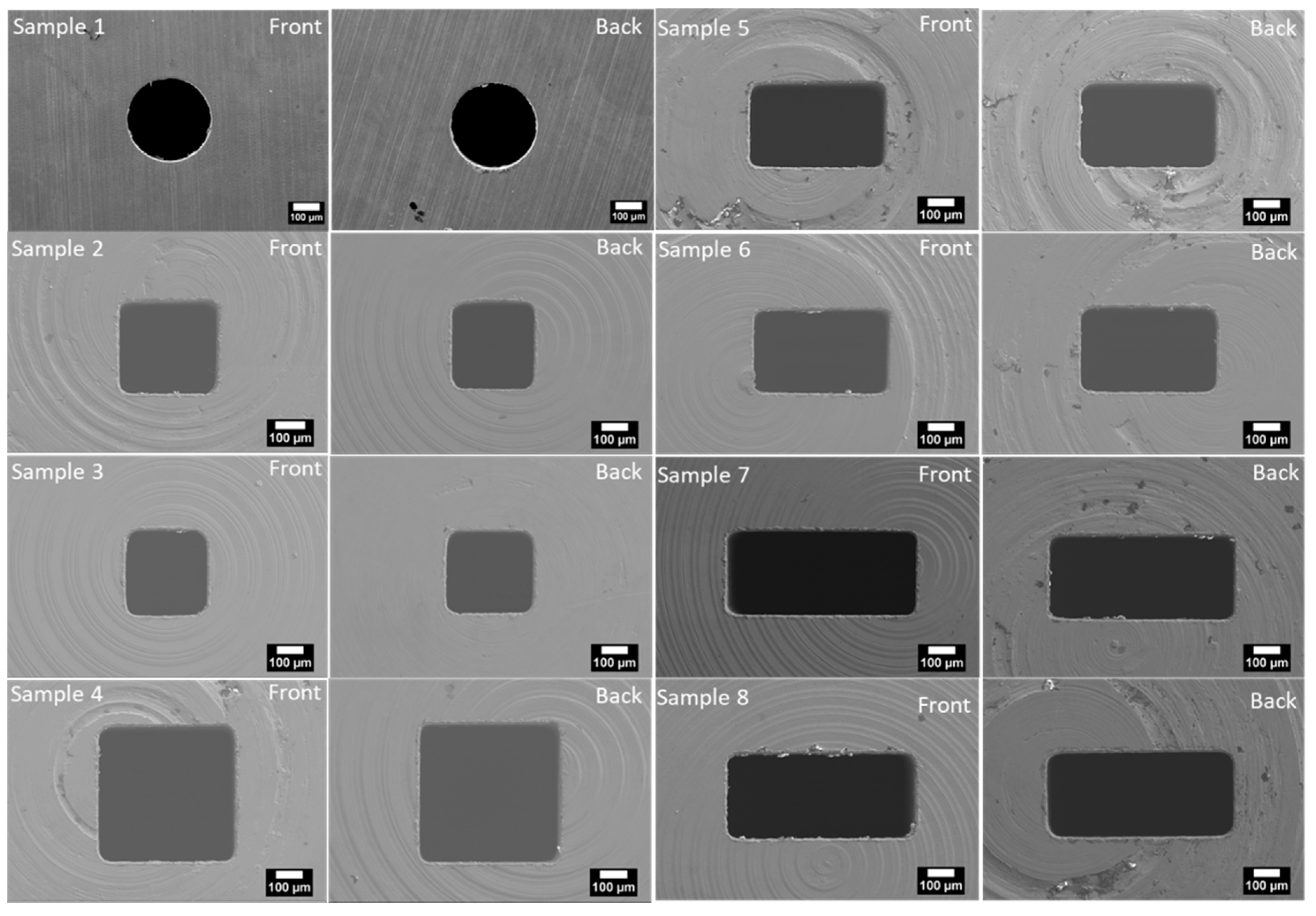
| Sample No. | (mm) | Cross-Section | |||||
|---|---|---|---|---|---|---|---|
| 1 | 927 ± 40 | 68.3 ± 4.6 | 295 ± 24 | 1.05 ± 0.01 | 3.56 | NA | Circular |
| 2 | 1210 ± 40 | 98.6 ± 6.0 | 326 ± 23 | 1.18 ± 0.01 | 3.62 | 1.06 | Square |
| 3 | 1209 ± 40 | 99.7 ± 6.0 | 330 ± 23 | 1.19 ± 0.01 | 3.61 | 1.05 | Square |
| 4 | 1958 ± 40 | 249.6 ± 9.8 | 510 ± 23 | 1.17 ± 0.01 | 2.29 | 1.00 | Square |
| 5 | 1571 ± 40 | 153.7 ± 7.8 | 391 ± 22 | 1.16 ± 0.01 | 2.97 | 1.58 | Rectangular |
| 6 | 1586 ± 40 | 155.6 ± 7.9 | 392 ± 22 | 1.24 ± 0.01 | 3.16 | 1.58 | Rectangular |
| 7 | 1946 ± 40 | 209.1 ± 9.7 | 430 ± 22 | 1.06 ± 0.01 | 2.46 | 2.23 | Rectangular |
| 8 | 1993 ± 40 | 221.9 ± 9.9 | 445 ± 22 | 1.11 ± 0.01 | 2.49 | 2.26 | Rectangular |
| Property | 298 K | 503 K |
|---|---|---|
| (kg/m3) | 1002 | 835.9 |
| (µPa s) | 891.6 | 118.7 |
© 2020 by the authors. Licensee MDPI, Basel, Switzerland. This article is an open access article distributed under the terms and conditions of the Creative Commons Attribution (CC BY) license (http://creativecommons.org/licenses/by/4.0/).
Share and Cite
Cassineri, S.; Cioncolini, A.; Smith, L.; Curioni, M.; Scenini, F. Experiments on Liquid Flow through Non-Circular Micro-Orifices. Micromachines 2020, 11, 510. https://doi.org/10.3390/mi11050510
Cassineri S, Cioncolini A, Smith L, Curioni M, Scenini F. Experiments on Liquid Flow through Non-Circular Micro-Orifices. Micromachines. 2020; 11(5):510. https://doi.org/10.3390/mi11050510
Chicago/Turabian StyleCassineri, Stefano, Andrea Cioncolini, Liam Smith, Michele Curioni, and Fabio Scenini. 2020. "Experiments on Liquid Flow through Non-Circular Micro-Orifices" Micromachines 11, no. 5: 510. https://doi.org/10.3390/mi11050510
APA StyleCassineri, S., Cioncolini, A., Smith, L., Curioni, M., & Scenini, F. (2020). Experiments on Liquid Flow through Non-Circular Micro-Orifices. Micromachines, 11(5), 510. https://doi.org/10.3390/mi11050510