A Method to Enhance Stroke Level of a MEMS Micromirror with Repulsive Electrostatic Force

Abstract
1. Introduction
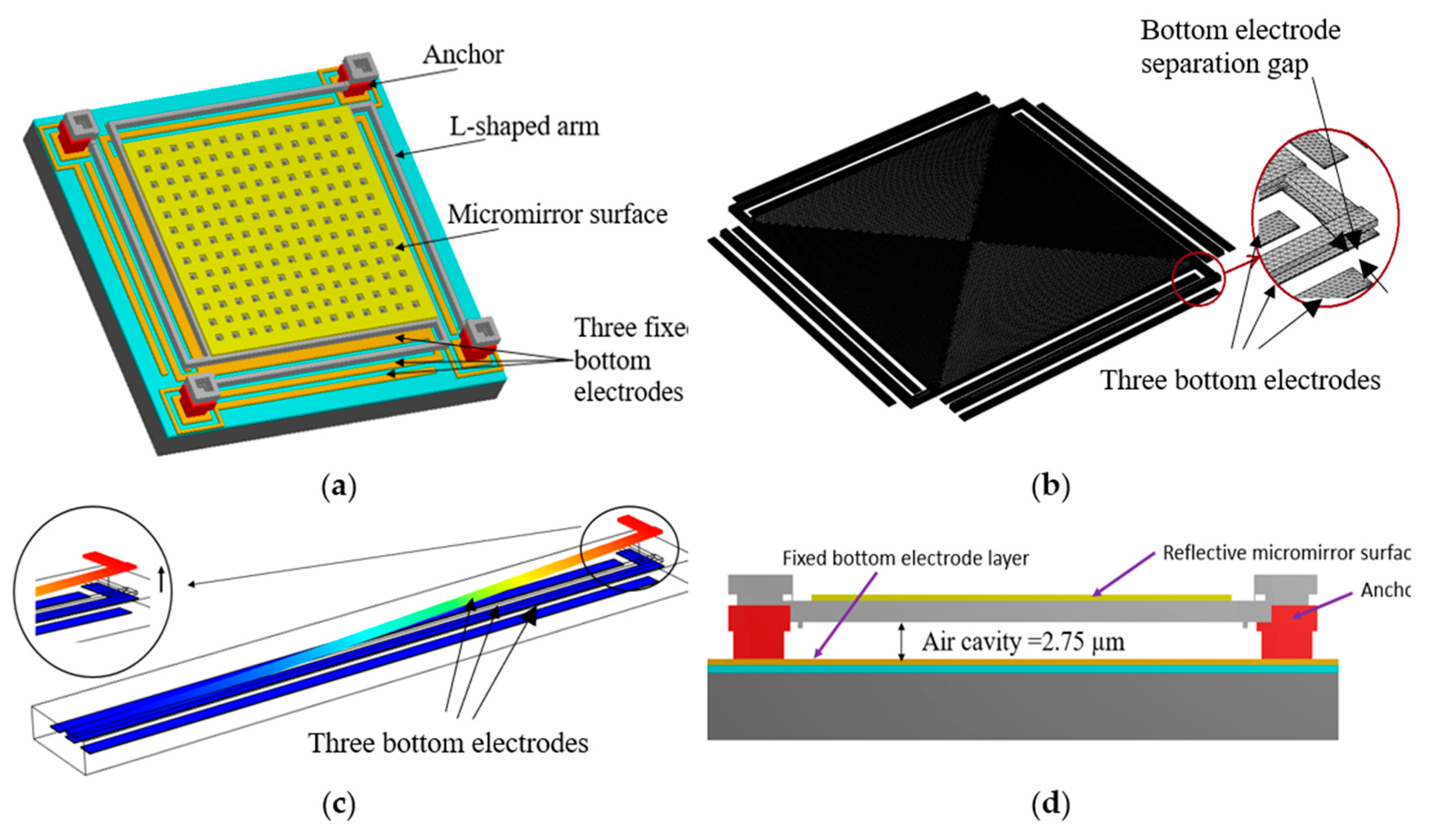
2. Micromirror Design
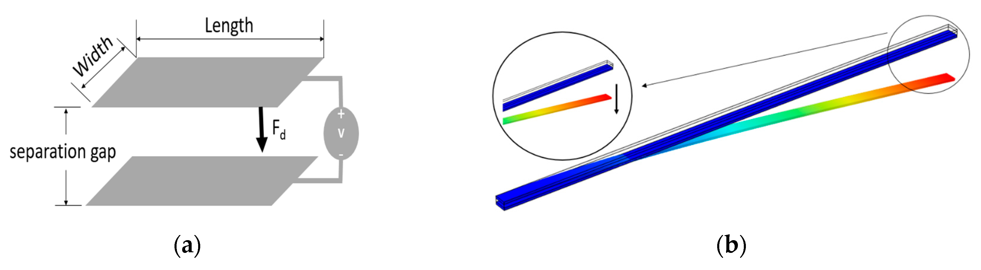
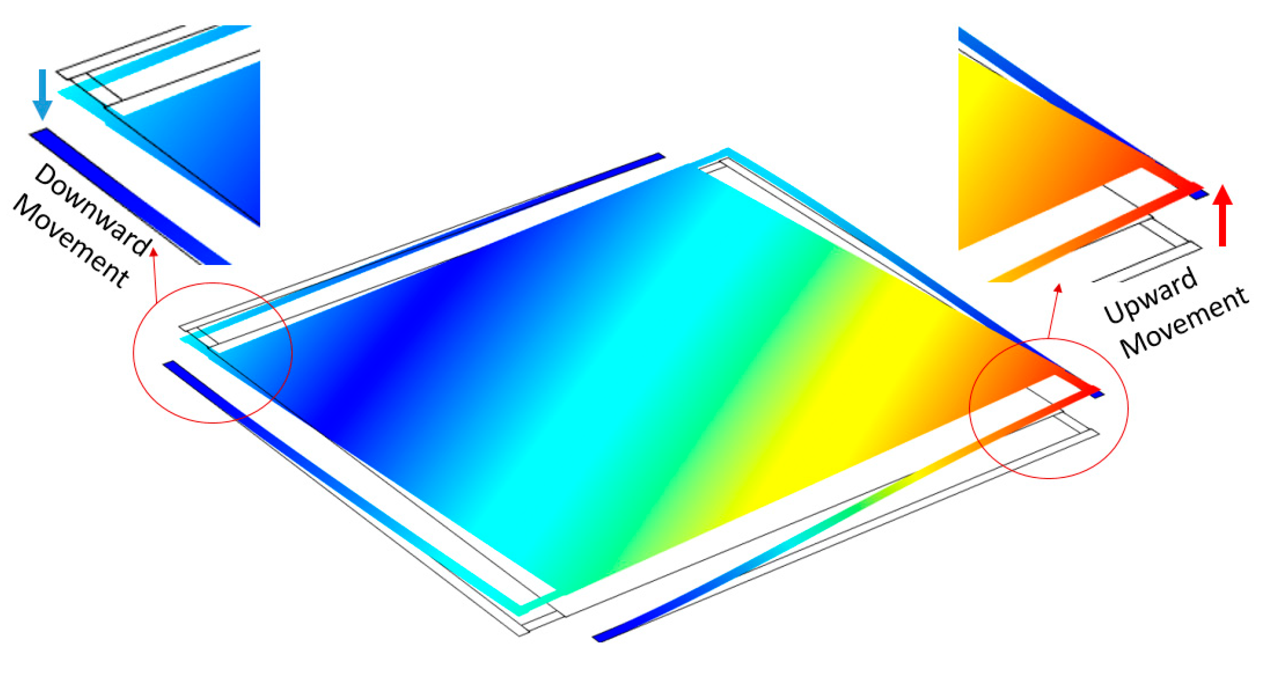
2.1. Principal of Operation
2.2. Micromirror Design Properties
3. Device Fabrication
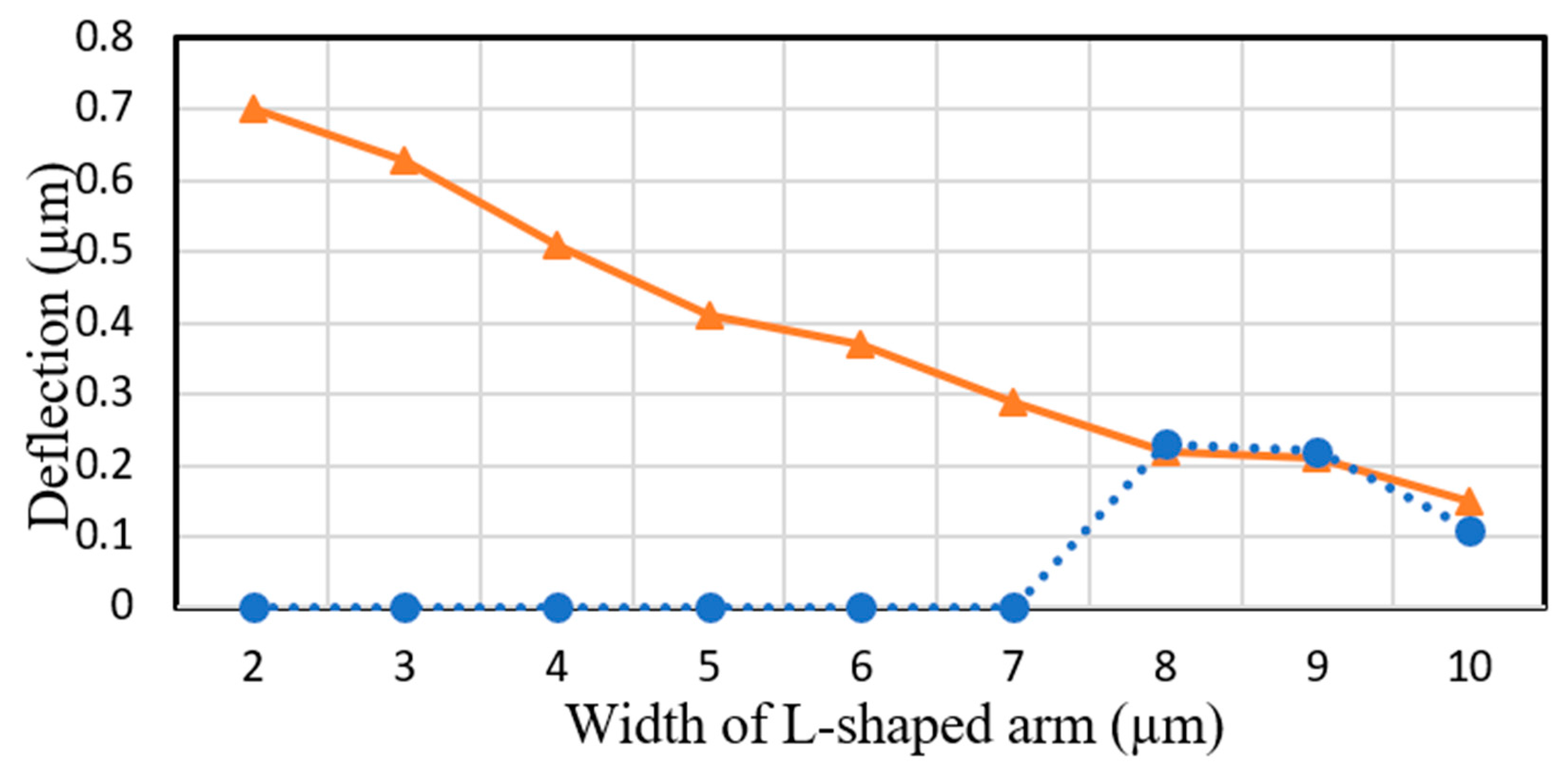
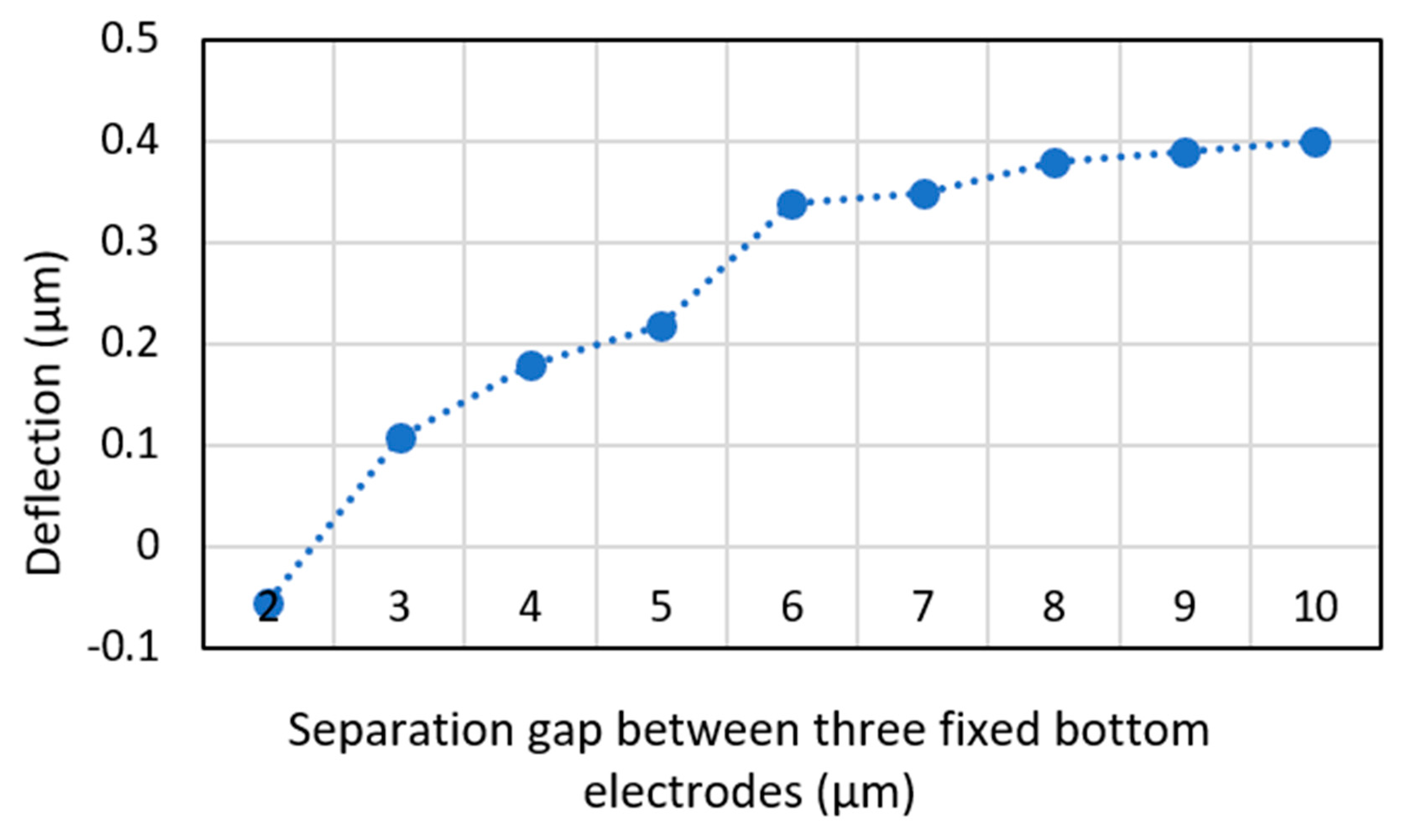
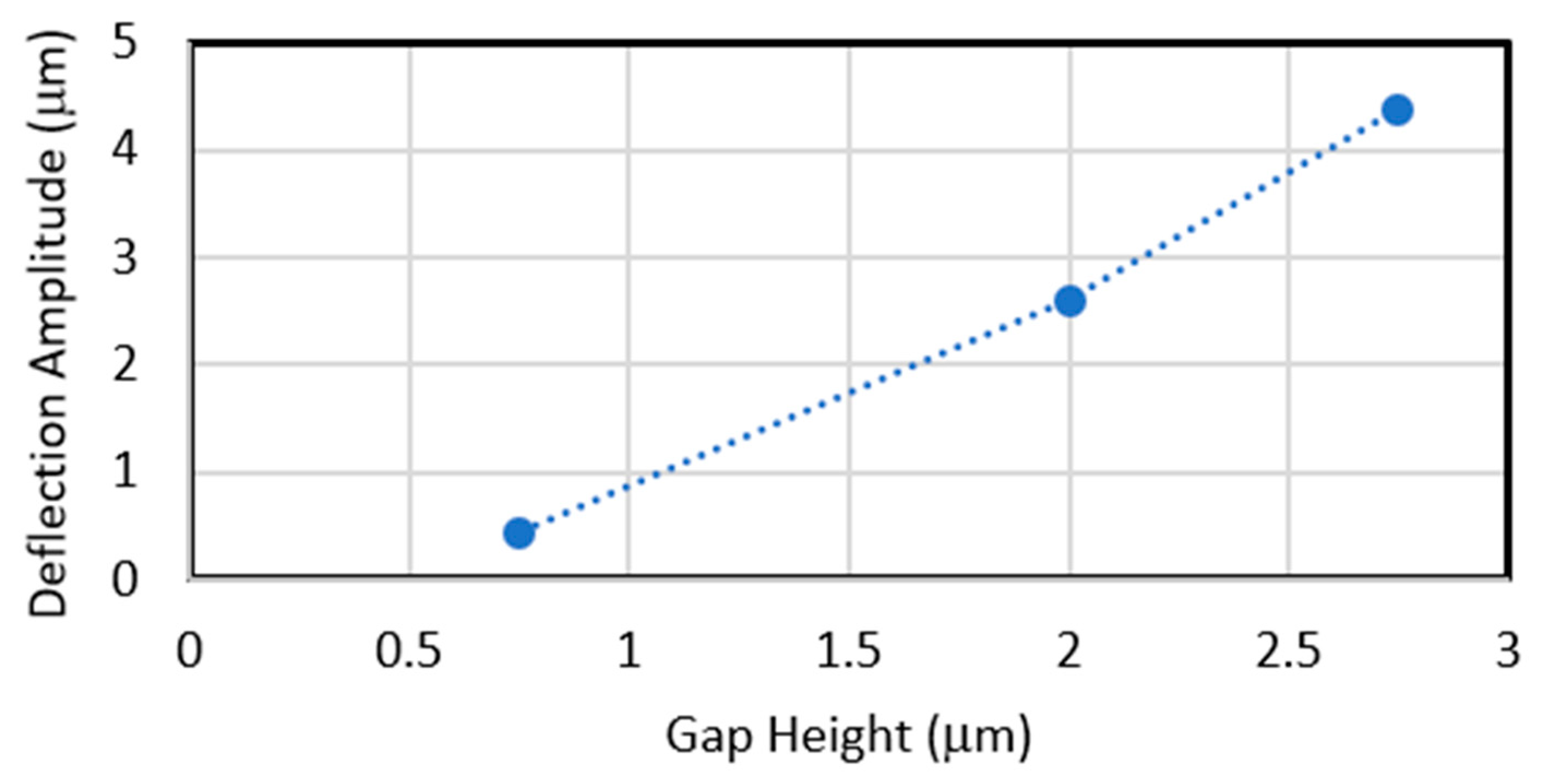
4. Design Evaluations
5. Conclusions
Author Contributions
Funding
Conflicts of Interest
References
- Heeren, H.V.; Salomon, P. MEMS Recent Developments, Future Directions. In Electronics Enabled Products Knowledge Transfer Network, Wolfson School of Mechanical and Manufacturing Engineering; Loughborough University: Loughborough, UK, 2007. [Google Scholar]
- He, S.; Mrad, R.B.; Chong, J. Repulsive-force out-of-plane large stroke translation micro electrostatic actuator. J. Micromechan. Microeng. 2011, 21, 7. [Google Scholar] [CrossRef]
- Hu, F.; Tang, Y.; Qian, Y. Design of a MEMS micromirror actuated by electrostatic repulsive force. Optik 2012, 123, 387–390. [Google Scholar] [CrossRef]
- Kumar, J.S.J.; Tetteh, E.A.; Braineard, E.P. A study of why electrostatic actuation is preferred and a simulation of an electrostatically actuated cantilever beam for mems applications. Int. J. Eng. Sci. Emerg. Technol. 2014, 6, 441–446. [Google Scholar]
- Kim, K.H.; Park, B.H.; Maguluri, G.N.; Lee, T.W.; Rogomentich, F.J.; Bancu, M.G.; Bouma, B.E.; de Boer, J.F.; Bernstein, J.J. Two-axis magnetically-driven MEMS scanning catheter for endoscopic high-speed optical coherence tomography. Opt. Express 2007, 15, 18130–18140. [Google Scholar] [CrossRef]
- Iseki, T.; Okumura, M.; Sugawara, T. Two-Dimensionally Deflecting Mirror Using Electromagnetic Actuation. Opt. Review 2006, 13, 189–194. [Google Scholar] [CrossRef]
- Smits, J.; Choi, W. The constituent equations of piezoelectric heterogeneous bimorphs. IEEE Trans. Ultrason. Ferroelectr. Freq. Control. 1991, 38, 256–270. [Google Scholar] [CrossRef]
- Fukunaga, M.; Takesada, M.; Onodera, A. Ferroelectricity in Layered Perovskites as a Model of Ultra-Thin Films. World J. Condens. Matt. Phys. 2012, 6, 224–243. [Google Scholar] [CrossRef]
- Lin, L.; Keeler, E. Progress of MEMS Scanning Micromirrors for Optical Bio-Imaging. Micromachines 2015, 6, 1675–1689. [Google Scholar] [CrossRef]
- Beeby, S.; Blackburn, A.; White, N. Processing of PZT piezoelectric thick-films on silicon for microelectromechanical systems. J. Micromechan. Microeng. 1999, 9, 218–229. [Google Scholar] [CrossRef]
- Bai, Y.; Yeow, J.T.W. Design, Fabrication, and Characteristics of a MEMS Micromirror with Sidewall Electrodes. J. Microelectromechan. Syst. 2010, 19, 619–631. [Google Scholar]
- Camon, H.; Ganibal, C. Advantages of alternative actuating signal for MEMS actuators. Sens. Actuat. A Phys. 2007, 136, 299–303. [Google Scholar] [CrossRef]
- Han, X.; Deng, Z.-F.; Xue, Y.-L.; Wang, Y.-Q.; Cao, L.-Q.; Han, L.; Zhou, B.-Y.; Li, M.-G. Laser 3D imaging technology based on digital micromirror device and the performance analysis. Optoelectron. Imag. Multim. Technol. III 2014, 9273, 10. [Google Scholar]
- Tsuchiya, T. MEMS mirrors for automotive applications. In Proceedings of the 2017 IEEE International Meeting for Future of Electron Devices, Kansai (IMFEDK), Kyoto, Japan, 29–30 June 2017. [Google Scholar]
- Sadeghian, H.; Rezazadeh, G.; Osterberg, P.M. Application of the Generalized Differential Quadrature Method to the Study of Pull-In Phenomena of MEMS Switches. J. Microelectromechan. Syst. 2007, 16, 1334–1340. [Google Scholar] [CrossRef]
- Degani, O.; Socher, E.; Lipson, A.; Leitner, T.; Setter, D.J.; Kaldor, S.; Nemirovsky, Y. Pull-In Study of an Electrostatic Torsion Microactuator. J. Microelectron. Syst. 1998, 7, 373–379. [Google Scholar] [CrossRef]
- Seeger, J.; Boser, B. Charge control of parallel-plate, electrostatic actuators and the tip-in instability. J. Microelectromechan. Syst. 2003, 12, 656–671. [Google Scholar] [CrossRef]
- Pengwang, E.; Rabenorosoa, K.; Rakotondrabe, M.; Andreff, N. Scanning Micromirror Platform Based on MEMS Technology for Medical Application. Micromachines 2016, 7, 24. [Google Scholar] [CrossRef]
- Helmbrecht, M.A.; Juneau, T.; Hart, M.; Doble, N. Segmented MEMS deformable-mirror technology for space applications. Proc. of SPIE 2006, 6223, 622305. [Google Scholar]
- Horenstein, M.N.; Pappasa, S.; Fishova, A.; Bifano, T.G. Electrostatic micromirrors for subaperturing in an adaptive optics system. J. Electrostat. 2002, 54, 321–332. [Google Scholar] [CrossRef]
- Cowen, A.; Hardy, B.; Mahadevan, R.; Wilcenski, S. PolyMUMPs Design Handbook; MEMSCAP Inc.: Crolles, France, 2011. [Google Scholar]
- Hu, F.; Yao, J.; Qiu, C.; Ren, H. A MEMS micromirror driven by electrostatic force. J. Electrostat. 2010, 68, 237–242. [Google Scholar] [CrossRef]
- Aryal, N.; Emadi, A. Novel method to improve stroke of electrostatically actuated MEMS micromirror. ODS 2019: Industr. Opt. Dev. Syst. 2019, 11125, 111250N. [Google Scholar]
- Micheal, A.; Kwok, C.Y. Monolithically integrated out-of-plane micro-mirror. Sens. Actuat. A Phys. 2011, 179, 263–276. [Google Scholar] [CrossRef]
- Das, K.; Batra, R.C. Pull-in and snap-through instabilities in transient deformations of microelectromechanical systems. J. Micromechan. Microeng. 2009, 19, 035008. [Google Scholar] [CrossRef]
- Zand, M.M.; Ahmadian, M.T. Application of homotopy analysis method in studying dynamic pull-in instability of microsystems. Mech. Res. Commun. 2009, 36, 851–858. [Google Scholar] [CrossRef]


| Layer. | Length | Width | Height | Separation |
|---|---|---|---|---|
| Reflective Surface | 400 µm | 400 µm | 0.5 µm | |
| Fixed Bottom Electrode | 400 µm | 10 µm | 0.5 µm | 8 µm |
| Arm | 400 µm | 8 µm | 2 µm | |
| Anchor | 50 µm | 50 µm | 2.5 µm | |
| Cavity | 2.75 µm |
| Mask Layer | Purpose |
|---|---|
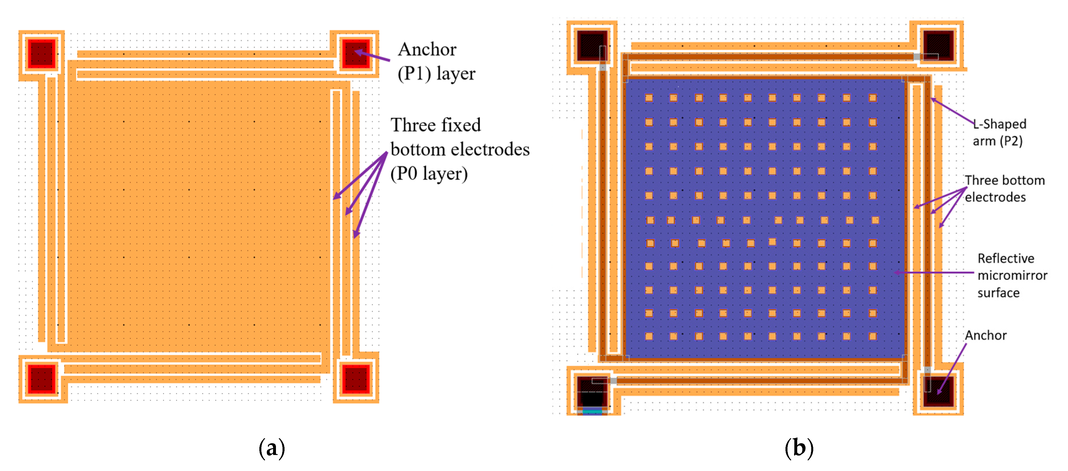
| POLY0 | Pattern P0 layer and create the bottom electrodes, Figure 6a |
| ANCHOR1 | Provide opening for P1 to be deposited on P0 on the four anchors of L-shaped arm by removing O1, Figure 6a |
| POLY1 | Pattern P1 on only the four anchors of L-shaped arms, Figure 6a and allow for the etching of the P1 layer from the rest of the device area and deposition of O2 directly on O1 |
| POLY1_POLY2_VIA | Provides opening for P1 to P2 connection by removing O2 from the four anchors of the L-shaped arms, Figure 6b |
| POLY2 | Pattern P2 layer on four arms and the micromirror, Figure 6b |
| METAL | Pattern metal layer on the micromirror surface area, Figure 6b |
| HOLEM and HOLE2 | Create releasing holes on metal and P2 layer to allow removal of O1 and O2 |
© 2020 by the authors. Licensee MDPI, Basel, Switzerland. This article is an open access article distributed under the terms and conditions of the Creative Commons Attribution (CC BY) license (http://creativecommons.org/licenses/by/4.0/).
Share and Cite
Aryal, N.; Emadi, A. A Method to Enhance Stroke Level of a MEMS Micromirror with Repulsive Electrostatic Force. Micromachines 2020, 11, 401. https://doi.org/10.3390/mi11040401
Aryal N, Emadi A. A Method to Enhance Stroke Level of a MEMS Micromirror with Repulsive Electrostatic Force. Micromachines. 2020; 11(4):401. https://doi.org/10.3390/mi11040401
Chicago/Turabian StyleAryal, Niwit, and Arezoo Emadi. 2020. "A Method to Enhance Stroke Level of a MEMS Micromirror with Repulsive Electrostatic Force" Micromachines 11, no. 4: 401. https://doi.org/10.3390/mi11040401
APA StyleAryal, N., & Emadi, A. (2020). A Method to Enhance Stroke Level of a MEMS Micromirror with Repulsive Electrostatic Force. Micromachines, 11(4), 401. https://doi.org/10.3390/mi11040401