Fluid Rheological Effects on the Flow of Polymer Solutions in a Contraction–Expansion Microchannel


Abstract
:1. Introduction
2. Experiment
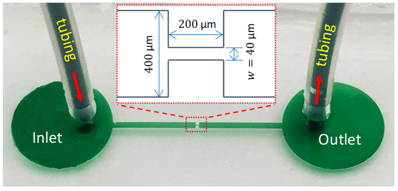
2.1. Microchannel
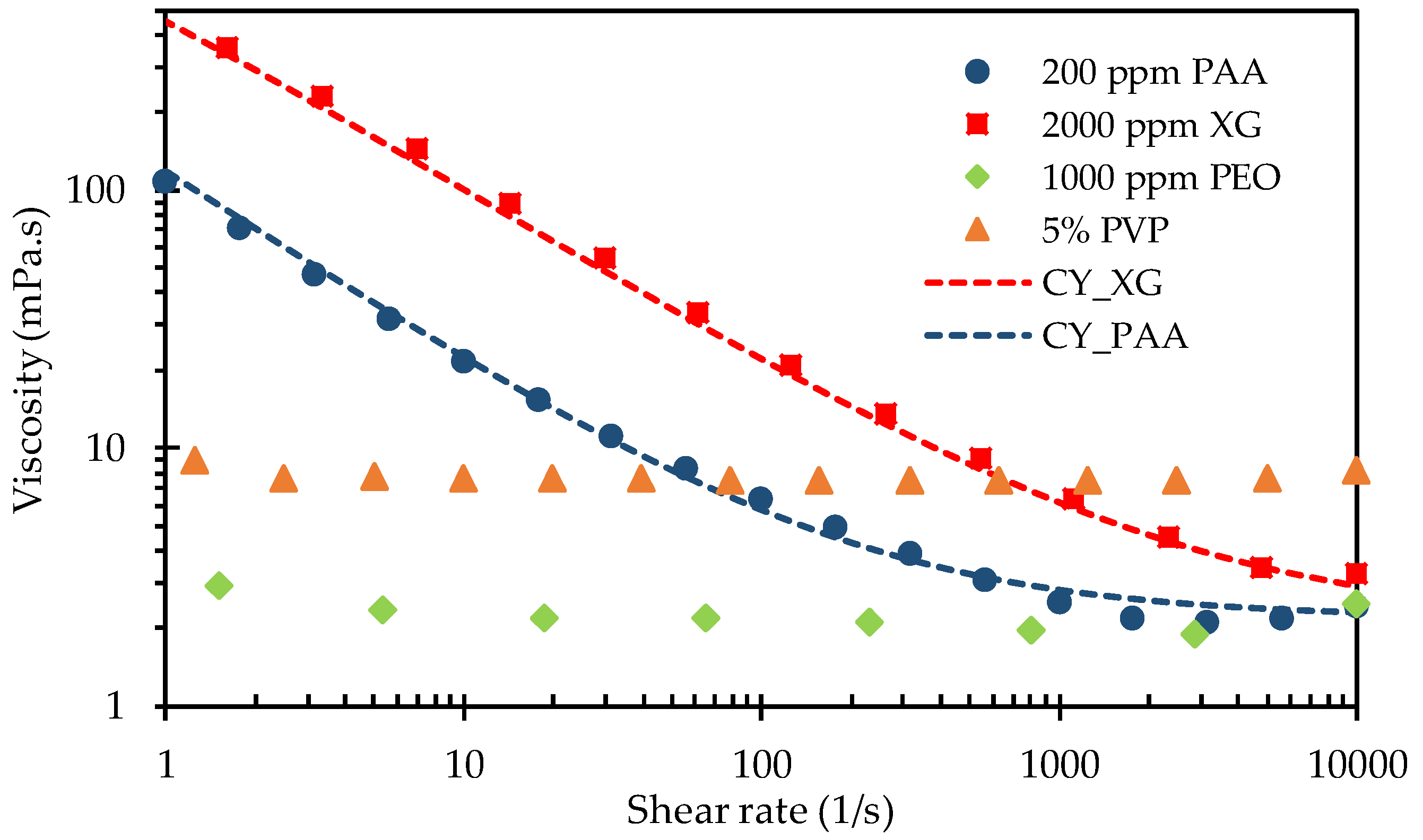
2.2. Fluids
2.3. Method
3. Results and Discussion
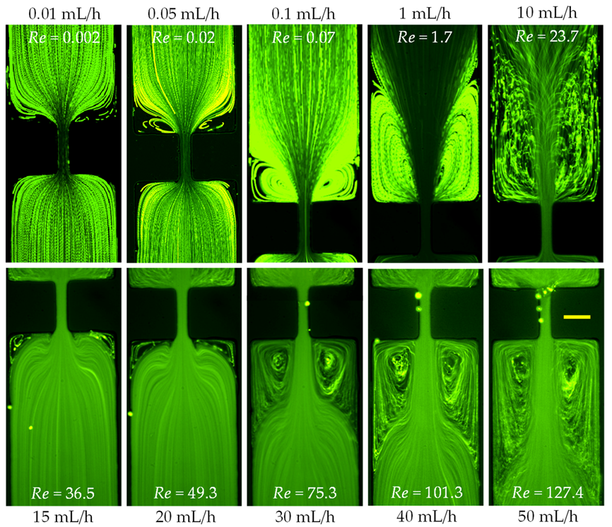
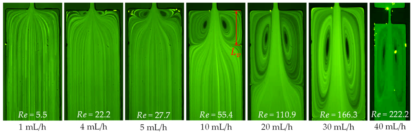
3.1. Effects of Inertia
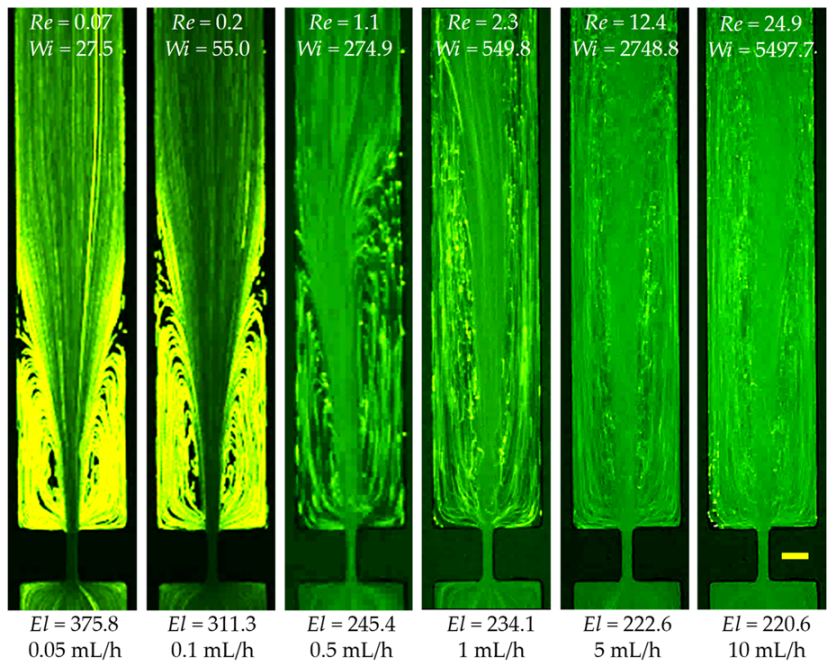
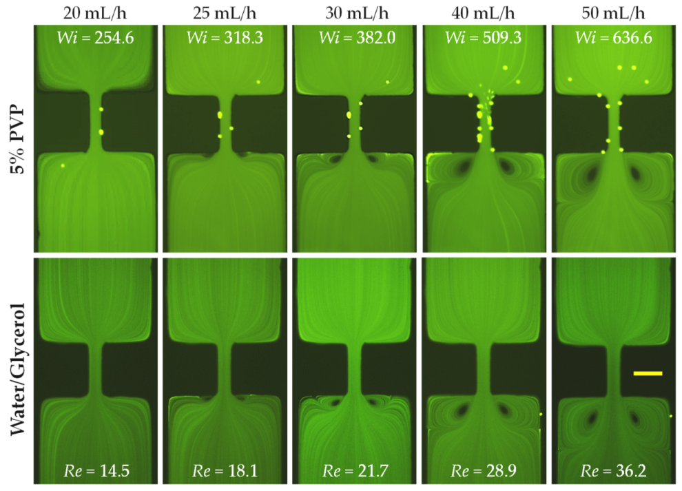
3.2. Effects of Elasticity and Inertia
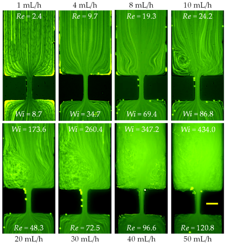
3.3. Effects of Shear Thinning and Inertia
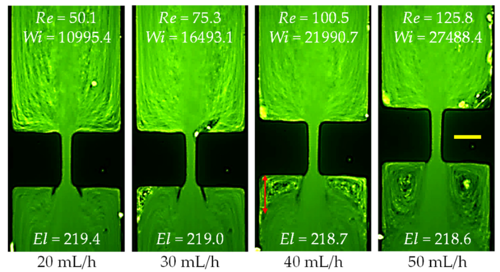
3.4. Effects of Elasticity, Shear Thinning and Inertia
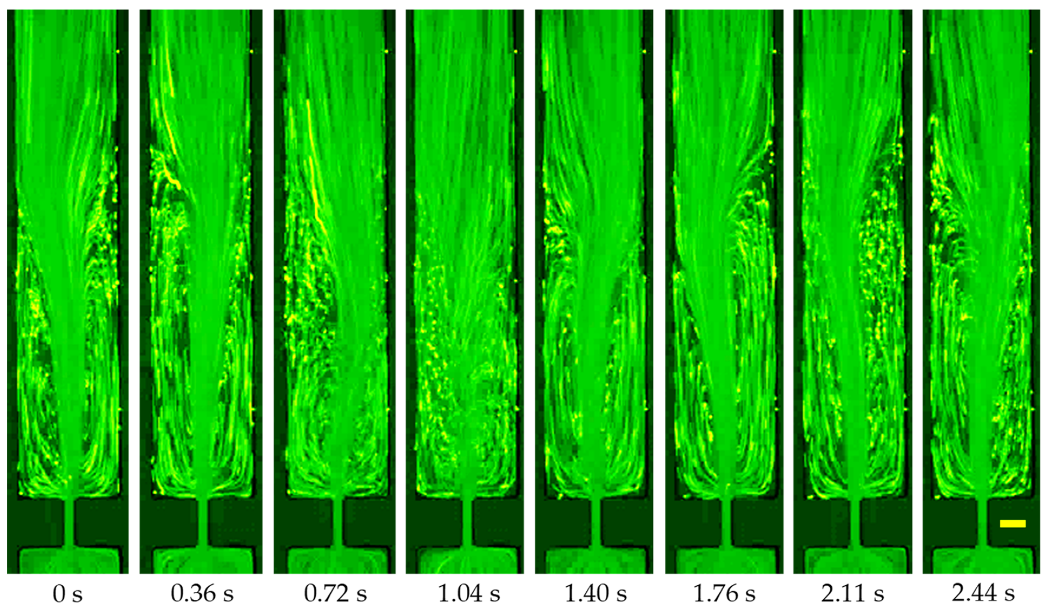
3.5. Effects of Elasticity, Shear Thinning, Inertia and More
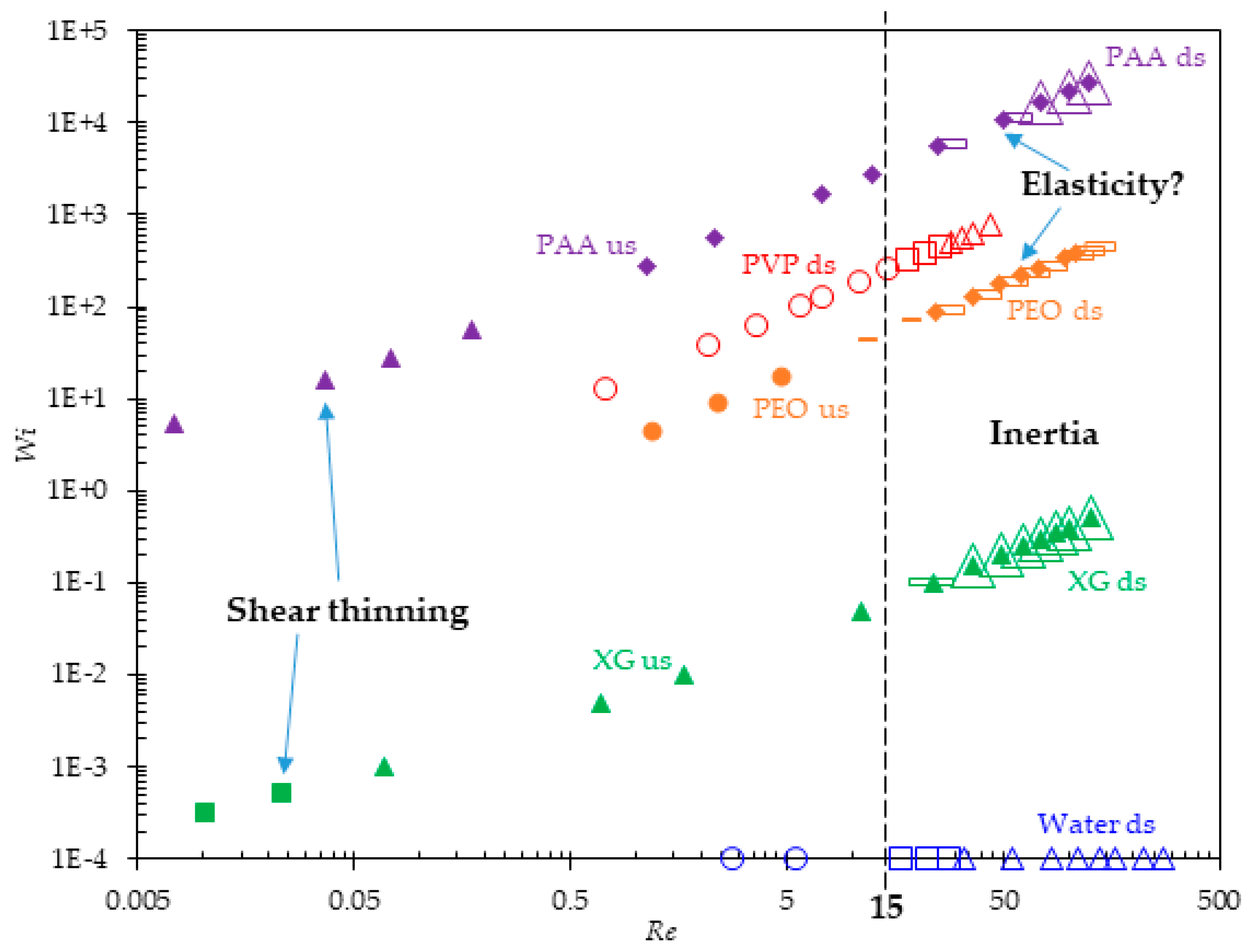
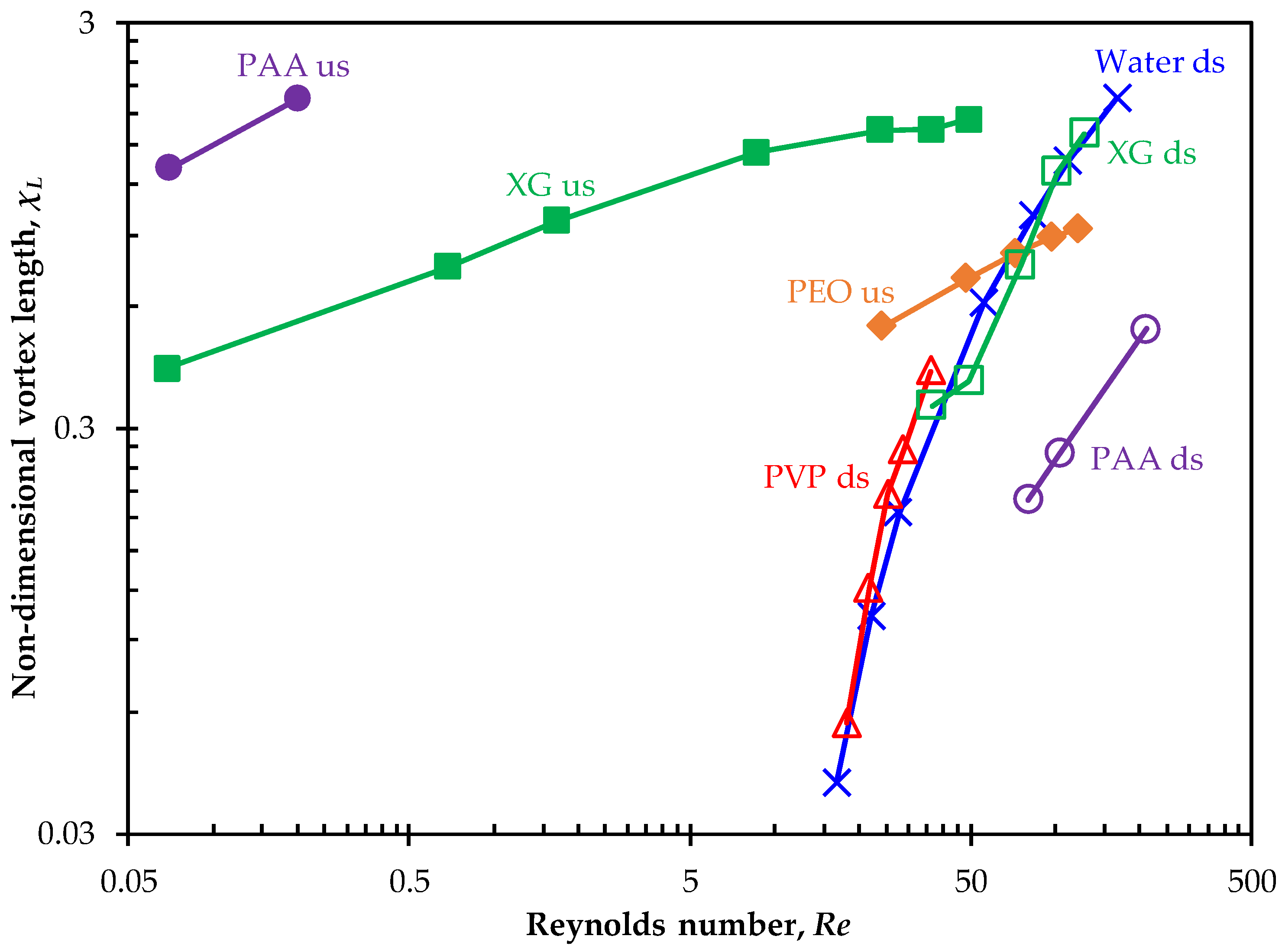
3.6. Summary of Flow Regimes and Vortex Development
3.7. Comparison with Other Polymer Solutions
4. Conclusions
Author Contributions
Funding
Conflicts of Interest
References
- Bird, R.B.; Armstrong, R.C.; Hassager, O. Dynamics of Polymeric Liquids; Wiley-Interscience: Hoboken, NJ, USA, 1987; Volume 1. [Google Scholar]
- Teraoka, I. Polymer Solutions: An Introduction to Physical Properties; John Wiley & Sons: Hoboken, NJ, USA, 2002. [Google Scholar]
- D’Avino, G.; Greco, F.; Maffettone, P.L. Particle migration due to viscoelasticity of the suspending liquid and its relevance in microfluidic devices. Annu. Rev. Fluid Mech. 2017, 49, 341–360. [Google Scholar] [CrossRef]
- Liu, C.; Hu, G. High-throughput particle manipulation based on hydrodynamic effects in microchannels. Micromachines 2017, 8, 73. [Google Scholar] [CrossRef] [Green Version]
- Lu, X.; Liu, C.; Hu, G.; Xuan, X. Particle manipulations in non-Newtonian microfluidics: A review. J. Colloid Interface Sci. 2017, 500, 182–201. [Google Scholar] [CrossRef] [PubMed] [Green Version]
- Yuan, D.; Zhao, Q.; Yan, S.; Tang, S.; Alici, G.; Zhang, J.; Li, W. Recent progress of particle migration in viscoelastic fluids. Lab Chip 2018, 18, 551–567. [Google Scholar] [CrossRef] [PubMed] [Green Version]
- Sorbie, K.S. Polymer-Improved Oil Recovery; Springer: Berlin/Heidelberg, Germany, 2013. [Google Scholar]
- Roote, D.S. Technology Status Report Insitu Flushing; Ground-Water Remediation Technologies Analysis Center: Pittsburgh, PA, USA, 1998. [Google Scholar]
- Barbati, A.C.; Desroches, J.; Robisson, A.; McKinley, G.H. Complex fluids and hydraulic fracturing. Annu. Rev. Chem. Biomol. Eng. 2016, 7, 415–453. [Google Scholar] [CrossRef] [PubMed] [Green Version]
- Browne, C.A.; Shih, A.; Datta, S.S. Pore-scale flow characterization of polymer solutions in microfluidic porous media. Small 2019. [Google Scholar] [CrossRef] [Green Version]
- Galindo-Rosales, F.J.; Campo-Deano, L.; Pinho, F.T.; van Bokhorst, E.; Hamersma, P.J.; Oliveira, M.S.N.; Alves, M.A. Microfluidic systems for the analysis of viscoelastic fluid flow phenomena in porous media. Microfluid. Nanofluid. 2012, 12, 485–498. [Google Scholar] [CrossRef] [Green Version]
- Anbari, A.; Chien, H.T.; Datta, S.S.; Deng, W.; Weitz, D.A.; Fan, J. Microfluidic model porous media: Fabrication and applications. Small 2018, 14, 1703575. [Google Scholar] [CrossRef]
- Gunda, N.S.; Bera, B.; Karadimitriou, N.K.; Mitra, S.K.; Hassanizadeh, S.M. Reservoir-on-a-chip (ROC): A new paradigm in reservoir engineering. Lab Chip 2011, 11, 3785–3792. [Google Scholar] [CrossRef] [Green Version]
- Kim, M.; Sell, A.; Sinton, D. Aquifer-on-a-chip: Understanding pore-scale salt precipitation dynamics during CO2 sequestration. Lab Chip 2013, 13, 2508–2518. [Google Scholar] [CrossRef]
- Galindo-Rosales, F.J.; Campo-Deaño, L.; Sousa, P.C.; Ribeiro, V.M.; Oliveira, M.S.N.; Alves, M.A.; Pinho, F.T. Viscoelastic instabilities in micro-scale flows. Exp. Therm. Fluid Sci. 2014, 59, 128–139. [Google Scholar] [CrossRef] [Green Version]
- Boger, D.V. Viscoelastic flows through contractions. Ann. Rev. Fluid Mech. 1987, 19, 157–182. [Google Scholar] [CrossRef]
- White, S.A.; Gotsis, A.D.; Baird, D.G. Review of the entry flow problem: Experimental and numerical. J. Nonnewton. Fluid Mech. 1987, 24, 121–160. [Google Scholar] [CrossRef]
- Alves, M.A.; Torres, D.; Concalves, M.; Oliveira, P.J.; Pinho, F.T. Visualization studies of viscoelastic flow in a 4:1 square/square contraction. In Proceedings of the 17th International Congress of Mechanical Engineering, Sao Paulo, Spain, 11–14 November 2003. [Google Scholar]
- Groisman, A.; Enzelberger, M.; Quake, S. Microfluidic memory and control devices. Science 2003, 300, 955–958. [Google Scholar] [CrossRef] [Green Version]
- Groisman, A.; Quake, S. A microfluidic rectifier: Anisotropic flow resistance at low Reynolds numbers. Phys. Rev. Lett. 2004, 92, 094501. [Google Scholar] [CrossRef] [Green Version]
- Rodd, L.E.; Scott, T.P.; Boger, D.V.; Cooper-White, J.J.; McKinley, G.H. The inertio-elastic planar entry flow of low-viscosity elastic fluids in micro-fabricated geometries. J. Nonnewton. Fluid Mech. 2005, 129, 1–22. [Google Scholar] [CrossRef] [Green Version]
- Rodd, L.E.; Cooper-White, J.J.; Boger, D.V.; McKinley, G.H. Role of the elasticity number in the entry flow of dilute polymer solutions in micro-fabricated contraction geometries. J. Nonnewton. Fluid Mech. 2007, 143, 170–191. [Google Scholar] [CrossRef]
- Oliveira, M.S.N.; Alves, M.A.; Pinho, F.T.; McKinley, G.H. Viscous flow through microfabricated hyperbolic contractions. Exp. Fluids 2007, 43, 437–451. [Google Scholar] [CrossRef]
- Oliveira, M.S.N.; Rodd, L.E.; McKinley, G.H.; Alves, M.A. Simulations of extensional flow in microrheometric devices. Microfluid. Nanofluid. 2008, 5, 809–826. [Google Scholar] [CrossRef] [Green Version]
- Campo-Deañoa, L.; Galindo-Rosales, F.J.; Pinho, F.T.; Alves, M.A.; Oliveira, M.S.N. Flow of low viscosity Boger fluids through a microfluidic hyperbolic contraction. J. Nonnewton. Fluid Mech. 2011, 166, 1286–1296. [Google Scholar] [CrossRef] [Green Version]
- Sousa, P.C.; Pinho, F.T.; Oliveira, M.S.N.; Alves, M.A. Extensional flow of blood analog solutions in microfluidic devices. Biomicrofluidics 2011, 5, 014108. [Google Scholar] [CrossRef] [PubMed] [Green Version]
- Lanzaro, A.; Yuan, X.F. Effects of contraction ratio on non-linear dynamics of semi-dilute, highly polydisperse PAAm solutions in microfluidics. J. Nonnewton. Fluid Mech. 2011, 166, 1064–1075. [Google Scholar] [CrossRef]
- Lanzaro, A.; Li, Z.; Yuan, X.F. Quantitative characterization of high molecular weight polymer solutions in microfluidic hyperbolic contraction flow. Microfluid. Nanofluid. 2015, 18, 819–828. [Google Scholar] [CrossRef]
- Hidema, R.; Oka, T.; Komoda, Y.; Suzuki, H. Effects of flexibility and entanglement of sodium hyaluronate in solutions on the entry flow in micro abrupt contraction-expansion channels. Phys. Fluids 2019, 31, 072005. [Google Scholar] [CrossRef]
- Matos, R.M.; Alves, M.A.; Pinho, F.T. Instabilities in micro-contraction flows of semi-dilute CTAB and CPyCl solutions: Rheology and flow instabilities. Exp. Fluids 2019, 60, 145. [Google Scholar] [CrossRef]
- Rodd, L.E.; Lee, D.; Ahn, K.H.; Cooper-White, J.J. The importance of downstream events in microfluidic viscoelastic entry flows: Consequences of increasing the constriction length. J. Nonnewton. Fluid Mech. 2010, 165, 1189–1203. [Google Scholar] [CrossRef]
- Li, Z.; Yuan, X.F.; Haward, S.J.; Odell, J.A.; Yeates, S. Non-linear dynamics of semi-dilute polydisperse polymer solutions in microfluidics: A study of a benchmark flow problem. J. Nonnewton. Fluid Mech. 2011, 166, 951–963. [Google Scholar] [CrossRef]
- Gan, H.Y.; Lam, Y.C.; Nguyen, N.T. Polymer-based device for efficient mixing of viscoelastic fluids. Appl. Phys. Lett. 2006, 88, 224103. [Google Scholar] [CrossRef]
- Gan, H.Y.; Lam, Y.C.; Nguyen, N.T.; Tam, K.C.; Yang, C. Efficient mixing of viscoelastic fluids in a microchannel at low Reynolds number. Microfluid. Nanofluid. 2007, 3, 101–108. [Google Scholar] [CrossRef]
- Lam, Y.C.; Gan, H.Y.; Nguyen, N.T.; Lie, H. Micromixer based on viscoelastic flow instability at low Reynolds number. Biomicrofluidics 2009, 3, 014106. [Google Scholar] [CrossRef] [Green Version]
- Japper-Jaafar, A.; Escudier, M.P.; Poole, R.J. Laminar, transitional and turbulent annular flow of drag-reducing polymer solutions. J. Nonnewton. Fluid Mech. 2010, 165, 1357–1372. [Google Scholar] [CrossRef]
- Liu, C.; Xue, C.; Chen, X.; Shan, L.; Tian, Y.; Hu, G. Size-based separation of particles and cells utilizing viscoelastic effects in straight microchannels. Anal. Chem. 2015, 87, 6041–6048. [Google Scholar] [CrossRef] [PubMed] [Green Version]
- Poole, R.J.; Escudier, M.P. Turbulent flow of viscoelastic liquids through an axisymmetric sudden expansion. J. Nonnewton. Fluid Mech. 2004, 117, 25–46. [Google Scholar] [CrossRef]
- Yasuda, K.; Armstrong, R.C.; Cohen, R.E. Shear flow properties of concentrated solutions of linear and star branched polystyrenes. Rheol. Acta 1981, 20, 163–178. [Google Scholar] [CrossRef]
- Di Carlo, D. Inertial microfluidics. Lab Chip 2009, 9, 3038–3046. [Google Scholar] [CrossRef]
- Lindner, A.; Bonn, D.; Meunier, J. Viscous fingering in a shear-thinning fluid. Phys. Fluids 2000, 12, 256–261. [Google Scholar] [CrossRef]
- James, D.F. Boger fluids. Annu. Rev. Fluid Mech. 2009, 41, 129–142. [Google Scholar] [CrossRef]
- Cheng, N.S. Formula for the viscosity of a glycerol−water mixture. Ind. Eng. Chem. Res. 2008, 47, 3285–3288. [Google Scholar] [CrossRef]
- Aytouna, M.; Paredes, J.; Shahidzadeh-Bonn, N.; Moulinet, S.; Wagner, C.; Amarouchene, Y.; Eggers, J.; Bonn, D. Drop formation in non-Newtonian fluids. Phys. Rev. Lett. 2013, 110, 034501. [Google Scholar] [CrossRef] [Green Version]
- Gulatia, S.; Muller, S.J.; Liepmanna, D. Direct measurements of viscoelastic flows of DNA in a 2:1 abrupt planar micro-contraction. J. Nonnewton. Fluid Mech. 2008, 155, 51–66. [Google Scholar] [CrossRef]
- Hemminger, O.L.; Boukany, P.E.; Wang, S.; Lee, J.J. Flow pattern and molecular visualization of DNA solutions through a 4:1 planar micro-contraction. J. Nonnewton. Fluid Mech. 2010, 165, 1613–1624. [Google Scholar] [CrossRef]
- Olson, D.J.; Fuller, G.G. Contraction and expansion flows of Langmuir monolayers. J. Nonnewton. Fluid Mech. 2000, 89, 187–207. [Google Scholar] [CrossRef]
- Haward, S.J.; Li, Z.; Lighter, D.; Thomas, B.; Odell, J.A.; Yuan, X.F. Flow of dilute to semi-dilute polystyrene solutions through a benchmark 8:1 planar abrupt micro-contraction. J. Nonnewton. Fluid Mech. 2010, 165, 1654–1669. [Google Scholar] [CrossRef]
- Miller, E.; Cooper-White, J. The effects of chain conformation in the microfluidic entry flow of polymer–surfactant systems. J. Nonnewton. Fluid Mech. 2009, 60, 22–30. [Google Scholar] [CrossRef]


| Fluid | n | ||||||
|---|---|---|---|---|---|---|---|
| DI Water | 1.0 | 1.0 | 1 | − | 1 | 0 | 0 |
| 5% PVP | 7.6 | 7.6 | 1 | − | ~1 | 2.2 * | 17.2 |
| 2000 ppm XG | 1870 | 2.1 | 6.62 | 1.02 | 0.32 | ~0 | ~0 |
| 1000 ppm PEO | 2.3 | 2.3 | − | − | ~1 | 1.5 ** | 3.6 |
| 200 ppm PAA | 4900 | 2.2 | 111.1 | 1.2 | 0.37 | 95 *** | 220.6 |
© 2020 by the authors. Licensee MDPI, Basel, Switzerland. This article is an open access article distributed under the terms and conditions of the Creative Commons Attribution (CC BY) license (http://creativecommons.org/licenses/by/4.0/).
Share and Cite
Jagdale, P.P.; Li, D.; Shao, X.; Bostwick, J.B.; Xuan, X. Fluid Rheological Effects on the Flow of Polymer Solutions in a Contraction–Expansion Microchannel. Micromachines 2020, 11, 278. https://doi.org/10.3390/mi11030278
Jagdale PP, Li D, Shao X, Bostwick JB, Xuan X. Fluid Rheological Effects on the Flow of Polymer Solutions in a Contraction–Expansion Microchannel. Micromachines. 2020; 11(3):278. https://doi.org/10.3390/mi11030278
Chicago/Turabian StyleJagdale, Purva P., Di Li, Xingchen Shao, Joshua B. Bostwick, and Xiangchun Xuan. 2020. "Fluid Rheological Effects on the Flow of Polymer Solutions in a Contraction–Expansion Microchannel" Micromachines 11, no. 3: 278. https://doi.org/10.3390/mi11030278
APA StyleJagdale, P. P., Li, D., Shao, X., Bostwick, J. B., & Xuan, X. (2020). Fluid Rheological Effects on the Flow of Polymer Solutions in a Contraction–Expansion Microchannel. Micromachines, 11(3), 278. https://doi.org/10.3390/mi11030278