Through-Mask Electrochemical Micromachining with Reciprocating Foamed Cathode

Abstract
1. Introduction
2. Principle of the Foamed Cathode TMEMM under the Magnetic Field
3. Experimentation
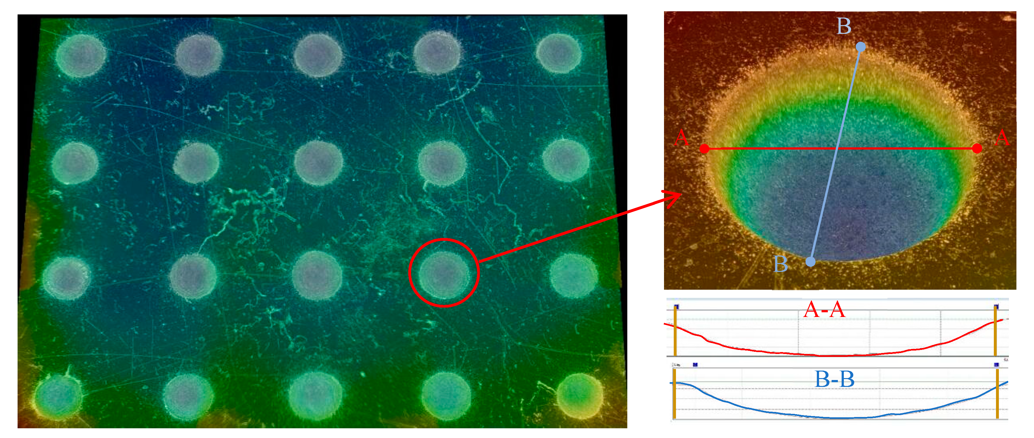
4. Results
4.1. Effect of the Magnetic Field
4.2. Effect of Machining Mode
4.3. Effect of the Applied Voltages and the Moving Speed of the Machining Assembly
5. Conclusions
- The modified foamed cathode TMEMM process facilitates the achievement of significant uniform micro-dimples with a favorable surface morphology. The coefficient of variation of the machined micro-dimple’s depth and diameter is reduced to 5.4% and 1.9%, respectively, and the minimum surface roughness Ra is 0.21–0.35 µm. This is mainly due to the cooperation of the significantly effective fixture of the through-mask on the workpiece by the magnetic field force and the improved mass transfer driven by the MHD effects.
- The modified foamed cathode TMEMM process is effective and practical only when it is carried out in a single-travel machining mode mainly because it eliminates the negative wake effect and the anodic dissolution process is kept in the highly efficient mass transfer state.
- For the modified foamed cathode, the applied voltage and the moving speed of the machining assemble need be matched appropriately. That is, higher applied voltages match bigger moving speeds of the machining assembly, and lower applied voltages correspond to lower moving speeds.
Author Contributions
Funding
Conflicts of Interest
References
- Lamers, E.; Walboomers, X.F.; Domanski, M.; Riet, J.; Delft, F.C.M.J.M.; Luttge, R.; Winnubst, L.A.J.A.; Gardeniers, H.J.G.E.; Jansen, J.A. The influence of nanoscale grooved substrates on osteoblast behavior and extracellular matrix deposition. Biomaterials 2010, 31, 3307–3316. [Google Scholar] [CrossRef]
- Evans, C.J.; Bryan, J.B. Structured, textured or engineered surfaces. CIRP Ann. Manuf. Technol. 1999, 48, 541–556. [Google Scholar] [CrossRef]
- Li, X.M.; Reinhoudt, D.; Crego-Calama, M. What do we need for a superhydrophobic surface? A review on the recent progress in the preparation of superhydrophobic surfaces. Chem. Soc. Rev. 2007, 36, 1350–1368. [Google Scholar] [CrossRef] [PubMed]
- Zhang, J.; Meng, Y. A study of surface texturing of carbon steel by photochemical machining. J. Mater. Process. Technol. 2012, 212, 2133–2140. [Google Scholar] [CrossRef]
- Amanov, A.; Pyoun, Y.S.; Cho, I.S.; Lee, C.S.; Park, I.G. Micro-dimpled surface by ultrasonic nanocrystal surface modification and its tribological effects. Wear 2012, 286, 136–144. [Google Scholar] [CrossRef]
- Burzynski, T.; Papini, M. Level set methods for the modelling of surface evolution in the abrasive jet micromachining of features used in MEMS and microfluidic devices. J. Micromech. Microeng. 2010, 20, 085004. [Google Scholar] [CrossRef]
- Demir, A.G.; Previtali, B.; Lecis, N. Development of laser dimpling strategies on TiN coatings for tribological applications with a highly energetic Q-switched fibre laser. Opt. Laser Technol. 2013, 54, 53–61. [Google Scholar] [CrossRef]
- Datta, M.; Landolt, D. Electrochemical machining under pulsed current conditions. Electrochi. Acta 1981, 26, 899–907. [Google Scholar] [CrossRef]
- Rajurkar, K.P.; Zhu, D.; Mcgeough, J.A.; Kozak, J.; DeSilva, A. New developments in electro-chemical machining. CIRP Ann. Manuf. Technol. 1999, 48, 567–579. [Google Scholar] [CrossRef]
- Costa, H.L.; Hutchings, I.M. Hydrodynamic lubrication of textured steel surfaces under reciprocating sliding conditions. Tribol. Int. 2007, 40, 1227–1238. [Google Scholar] [CrossRef]
- Costa, H.L.; Hutchings, I.M. Effects of die surface patterning on lubrication in strip drawing. J. Mater. Process. Technol. 2009, 209, 1175–1180. [Google Scholar] [CrossRef]
- Datta, M.; Harris, D. Electrochemical micromachining: An environmentally friendly, high speed processing technology. Electrochi. Acta 1997, 42, 3007–3013. [Google Scholar] [CrossRef]
- Chauvy, P.F.; Hoffmann, P.; Landolt, D. Applications of laser lithography on oxide film to titanium micromachining. Appl. Surf. Sci. 2003, 208, 165–170. [Google Scholar] [CrossRef]
- Landolt, D.; Chauvy, P.F.; Zinger, O. Electrochemical micromachining, polishing and surface structuring of metals: Fundamental aspects and new developments. Electrochi. Acta 2003, 48, 3185–3201. [Google Scholar] [CrossRef]
- Asoh, H.; Oide, A.; Ono, S. Formation of microstructured silicon surfaces by electrochemical etching using colloidal crystal as mask. Electrochem. Commun. 2006, 8, 1817–1820. [Google Scholar] [CrossRef]
- Schönenberger, I.; Roy, S. Microscale pattern transfer without photolithography of substrates. Electrochi. Acta 2005, 51, 809–819. [Google Scholar] [CrossRef]
- Costa, H.L.; Hutchings, I.M. Development of a maskless electrochemical texturing method. J. Mater. Process. Technol. 2009, 209, 3869–3878. [Google Scholar] [CrossRef]
- Parreira, J.G.; Gallo, C.A.; Costa, H.L. New advances on maskless electrochemical texturing (MECT) for tribological purposes. Surf. Coat Technol. 2012, 212, 1–13. [Google Scholar] [CrossRef]
- Qu, N.S.; Chen, X.L.; Li, H.S.; Zeng, Y.B. Electrochemical micromachining of micro-dimple arrays on cylindrical inner surfaces using a dry-film photoresist. Chin. J. Aeronaut. 2014, 27, 1030–1036. [Google Scholar] [CrossRef]
- Qu, N.S.; Zhang, X.F.; Chen, X.L.; Li, H.S.; Zhu, D. Modified microscale pattern transfer without photolithography of substrates. J. Mater. Process. Technol. 2015, 218, 71–79. [Google Scholar] [CrossRef]
- Zhang, X.F.; Qu, N.S.; Chen, X.L. Sandwich-like electrochemical micromachining of micro-dimples. Surf. Coat Technol. 2016, 302, 438–447. [Google Scholar] [CrossRef]
- Zhu, D.; Qu, N.S.; Li, H.S.; Zeng, Y.B.; Li, D.L.; Qian, S.Q. Electrochemical micromachining of microstructures of micro hole and dimple array. CIRP Ann. Manuf. Technol. 2009, 58, 177–180. [Google Scholar] [CrossRef]
- Qian, S.Q.; Zhu, D.; Qu, N.S.; Li, H.S.; Yan, D.S. Generating micro-dimples array on the hard chrome-coated surface by modified through mask electrochemical micromachining. Int. J. Adv. Manuf. Technol. 2010, 47, 1121–1127. [Google Scholar] [CrossRef]
- Li, D.L.; Zhu, D.; Li, H.S.; Liu, J.G. Effects of mask wall angle on matrix-hole shape changes during electrochemical machining by mask. J. Cent. South Univ. Technol. 2011, 18, 1115–1120. [Google Scholar] [CrossRef]
- Chen, X.L.; Qu, N.S.; Li, H.S.; Zhu, D. The fabrication and application of a PDMS micro through-holes mask in electrochemical micromanufacturing. Adv. Mech. Eng. 2014, 6, 943092. [Google Scholar] [CrossRef]
- Qu, N.S.; Chen, X.L.; Li, H.S.; Zhu, D. Fabrication of PDMS micro through-holes for electrochemical micromachining. Int. J. Adv. Manuf. Technol. 2014, 72, 487–494. [Google Scholar] [CrossRef]
- Chen, X.L.; Qu, N.S.; Li, H.S.; Guo, Z. Removal of islands from micro-dimple arrays prepared by through-mask electrochemical micromachining. Precis. Eng. 2015, 39, 204–211. [Google Scholar] [CrossRef]
- Chen, X.L.; Qu, N.S.; Li, H.S.; Xu, Z.Y. Electrochemical micromachining of micro-dimple arrays using a polydimethylsiloxane (PDMS) mask. J. Mater. Process. Technol. 2016, 229, 102–110. [Google Scholar] [CrossRef]
- Ming, P.M.; Zhou, W.H.; Zhao, C.H.; Zhou, H.M.; Qin, G.; Zhang, X.M. Development of a modified through-mask electrochemical micromachining for micropatterning nonplanar surface. Int. J. Adv. Manuf. Technol. 2017, 93, 2613–2623. [Google Scholar] [CrossRef]
- Ming, P.M.; Zhao, C.H.; Zhang, X.M.; Li, X.C.; Qin, G.; Yan, L. Investigation of foamed cathode through-mask electrochemical micromachining developed for uniform texturing on metallic cylindrical surface. Int. J. Adv. Manuf. Technol. 2018, 96, 3043–3056. [Google Scholar] [CrossRef]
- Weston, M.C.; Gerner, M.D.; Fritsch, I. Magnetic Fields for Fluid Motion. Anal. Chem. 2010, 82, 3411–3418. [Google Scholar] [CrossRef] [PubMed]
- Lau, A.; Fahidy, T.Z. A flow visualization study of the cathode geometry effect in magnetoelectrolytic cells. J. Electrochem. Soc. 1989, 136, 1401–1408. [Google Scholar] [CrossRef]
- Gu, Z.H.; Fahidy, T.Z. The effect of magnetic fields on electrolytic convection generated at inclined cylindrical cathodes. J. Electrochem. Soc. 1987, 134, 2241–2248. [Google Scholar] [CrossRef]
- Mohanta, S.; Fahidy, T.Z. Hydrodynamic and mass transport phenomena in a multiple-electrode magnetoelectrolytic cell. J. Appl. Electrochem. 1978, 8, 5–10. [Google Scholar] [CrossRef]
- Pa, P.S. Super finishing with ultrasonic and magnetic assistance in electrochemical micro-machining. Electrochi. Acta 2009, 54, 6022–6027. [Google Scholar] [CrossRef]
- Fan, Z.J.; Wang, T.C.; Zhong, L. The mechanism of improving machining accuracy of ECM by magnetic field. J. Mater. Process. Technol. 2004, 149, 409–413. [Google Scholar] [CrossRef]
- Matsushima, H.; Ispas, A.; Bund, A.; Bozzini, B. Magnetic field effects on the initial stages of electrodeposition processes. J. Electroanal. Chem. 2008, 615, 191–196. [Google Scholar] [CrossRef]
- Grant, K.M.; Hemmert, J.W.; White, H.S. Magnetic field-controlled microfluidic transport. J. Am. Chem. Soc. 2002, 124, 462–467. [Google Scholar] [CrossRef]
- Dou, H.S.; Phan-Thien, N. Negative wake in the uniform flow past a cylinder. Rheol. Acta 2003, 42, 383–409. [Google Scholar] [CrossRef]


| Items (Unit) | Values or Variables |
|---|---|
| Electrolyte | 10 wt% NaNO3 |
| Temperature (°C) | 25 |
| Material of the through-mask | Polyvinyl chloride (PVC) |
| Mask thickness (mm) | 0.1 |
| Mask hole diameter (mm) | 0.2 |
| Amount of mask holes | 121 |
| Magnetic flux density (T) | 0.2 |
| DC voltage (V) | 6.5~9 |
| Single-travel distance (m) | 0.15 |
| Single-travel time (s) | 0.3, 0.5, and 0.7 |
| Moving speed of machining assembly (m/s) | 0.5, 0.3, and 0.2 |
© 2020 by the authors. Licensee MDPI, Basel, Switzerland. This article is an open access article distributed under the terms and conditions of the Creative Commons Attribution (CC BY) license (http://creativecommons.org/licenses/by/4.0/).
Share and Cite
Zhao, C.; Ming, P.; Zhang, X.; Qin, G.; Shen, J.; Yan, L.; Zheng, X.; Cao, J. Through-Mask Electrochemical Micromachining with Reciprocating Foamed Cathode. Micromachines 2020, 11, 188. https://doi.org/10.3390/mi11020188
Zhao C, Ming P, Zhang X, Qin G, Shen J, Yan L, Zheng X, Cao J. Through-Mask Electrochemical Micromachining with Reciprocating Foamed Cathode. Micromachines. 2020; 11(2):188. https://doi.org/10.3390/mi11020188
Chicago/Turabian StyleZhao, Chenhao, Pingmei Ming, Xinmin Zhang, Ge Qin, Jiwen Shen, Liang Yan, Xingshuai Zheng, and Jun Cao. 2020. "Through-Mask Electrochemical Micromachining with Reciprocating Foamed Cathode" Micromachines 11, no. 2: 188. https://doi.org/10.3390/mi11020188
APA StyleZhao, C., Ming, P., Zhang, X., Qin, G., Shen, J., Yan, L., Zheng, X., & Cao, J. (2020). Through-Mask Electrochemical Micromachining with Reciprocating Foamed Cathode. Micromachines, 11(2), 188. https://doi.org/10.3390/mi11020188