Performance Evaluation of a Piezoelectric Energy Harvester Based on Flag-Flutter

 ,
,  , and
, and
Abstract
1. Introduction
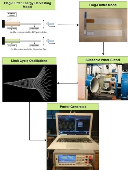
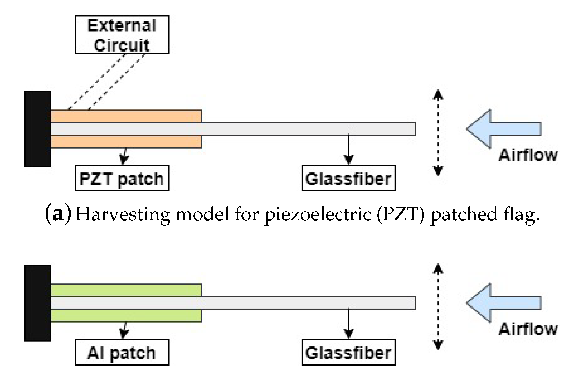
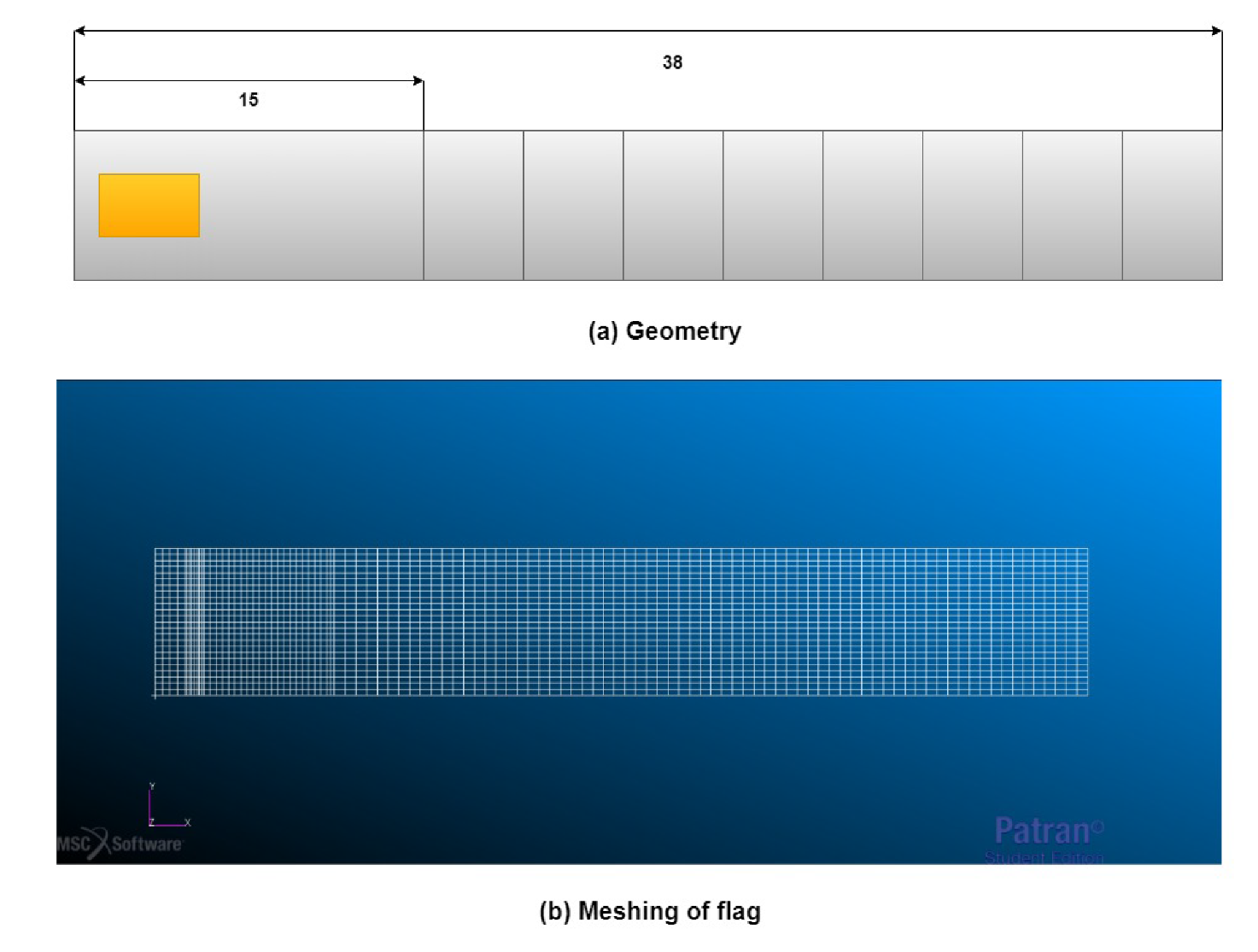
2. Numerical Model
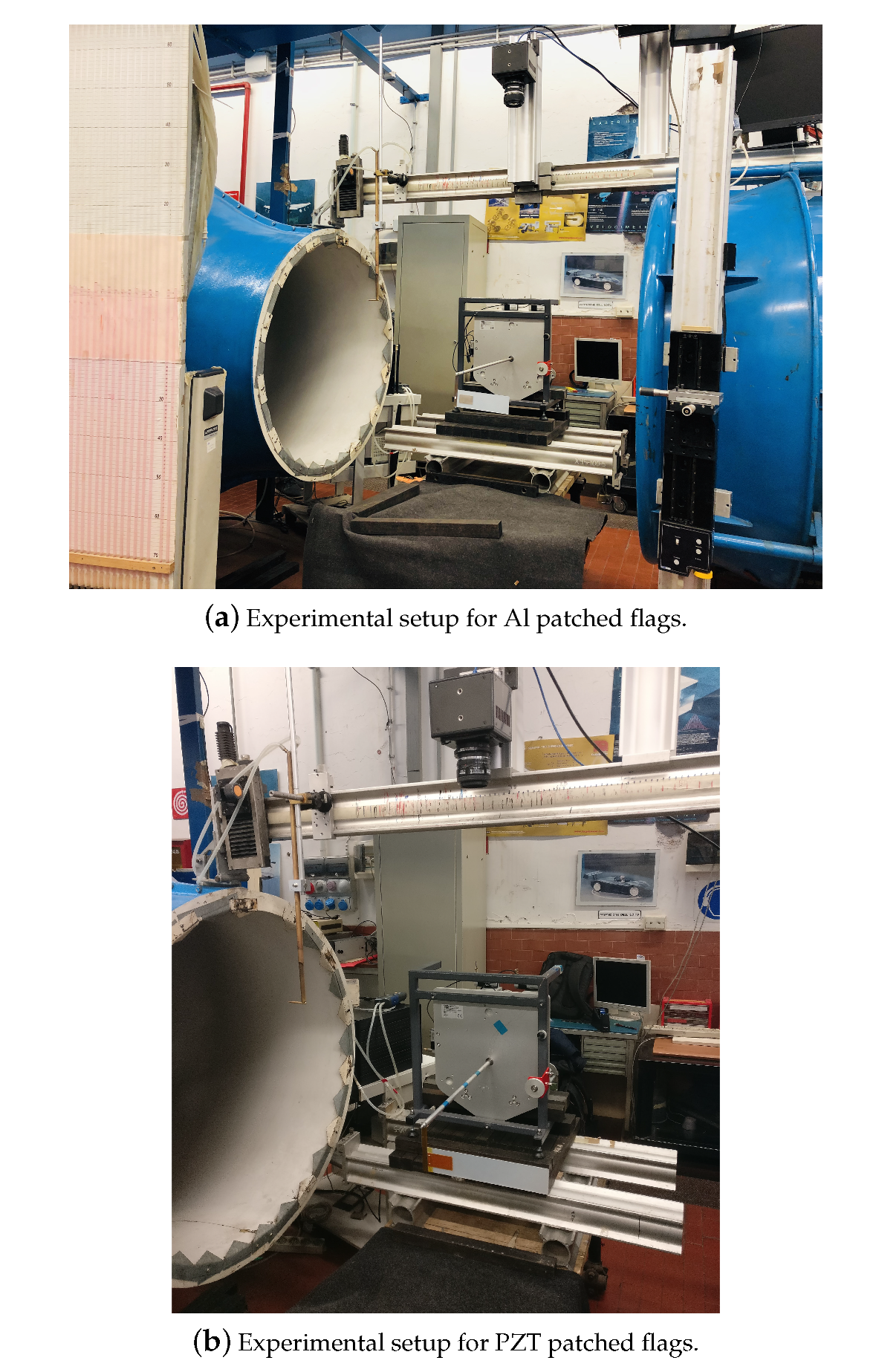
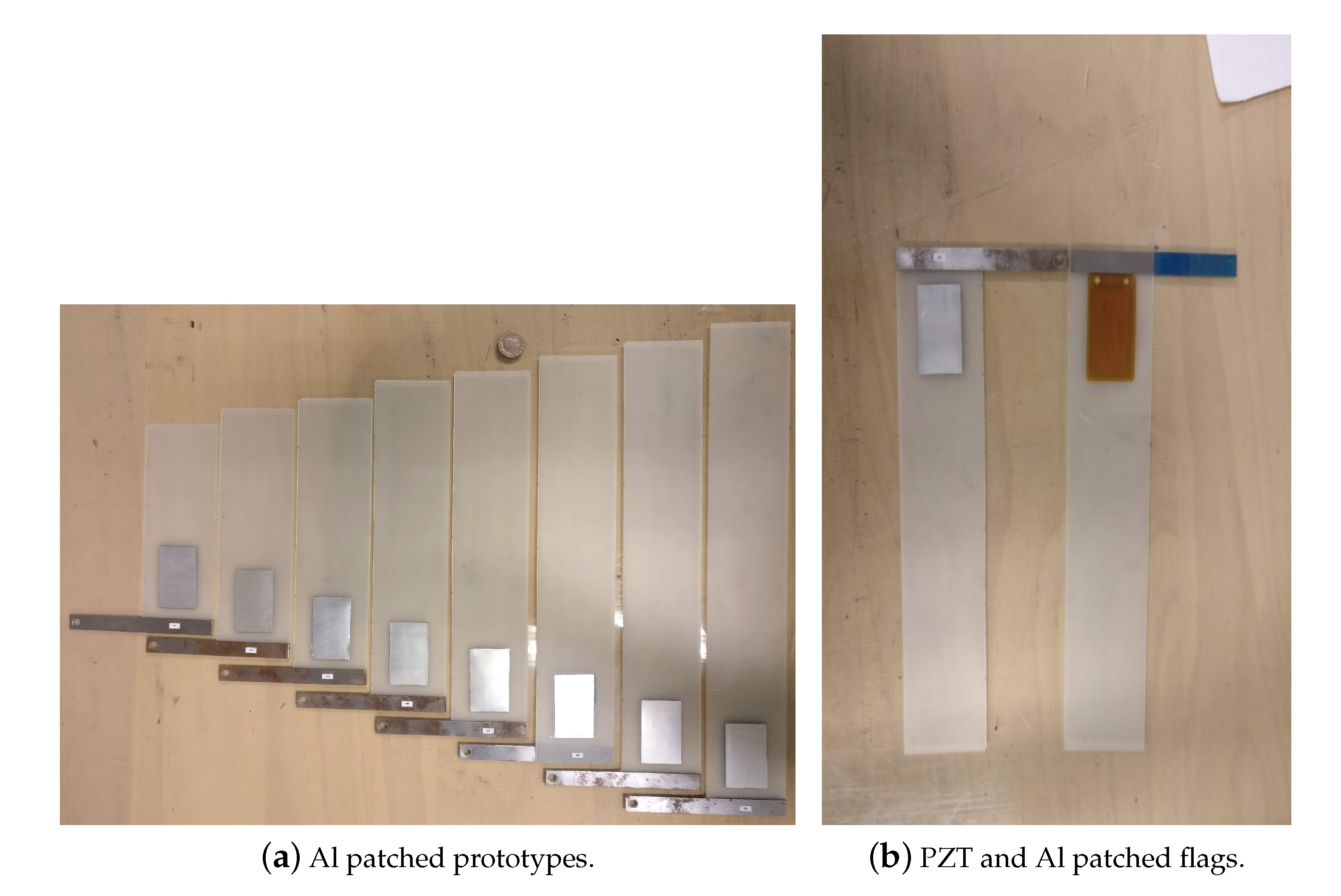
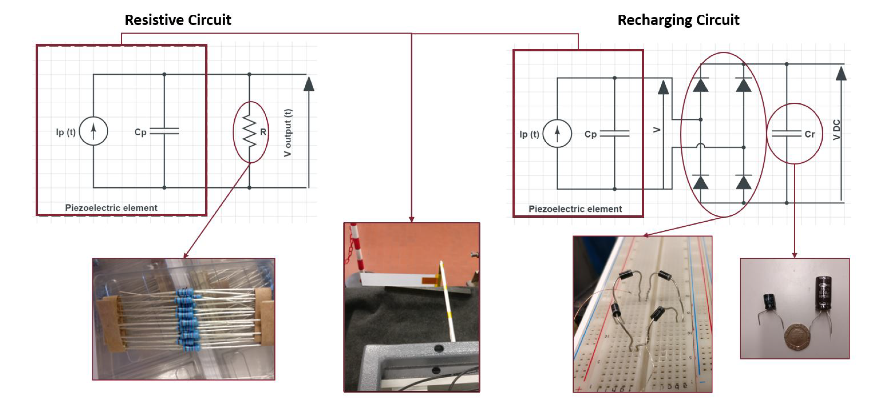
3. Experimental Setup
4. Results and Discussion
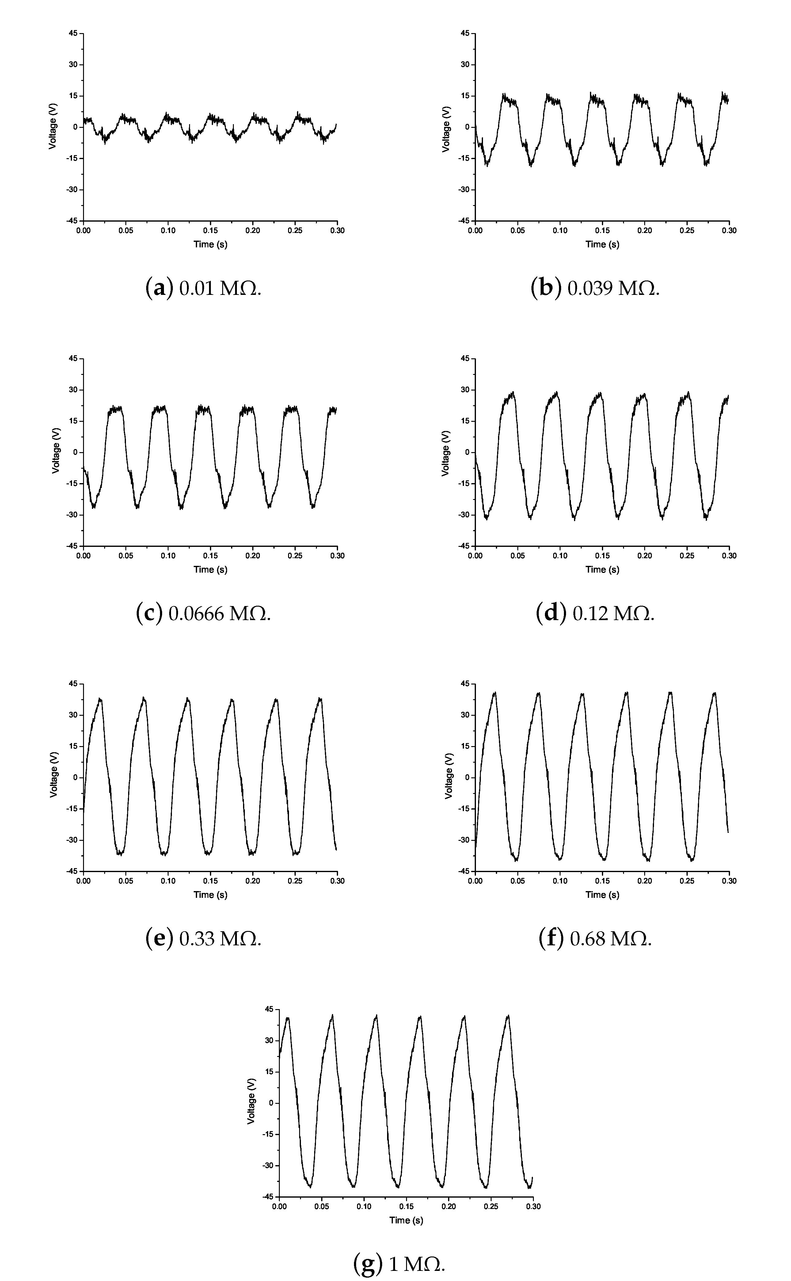
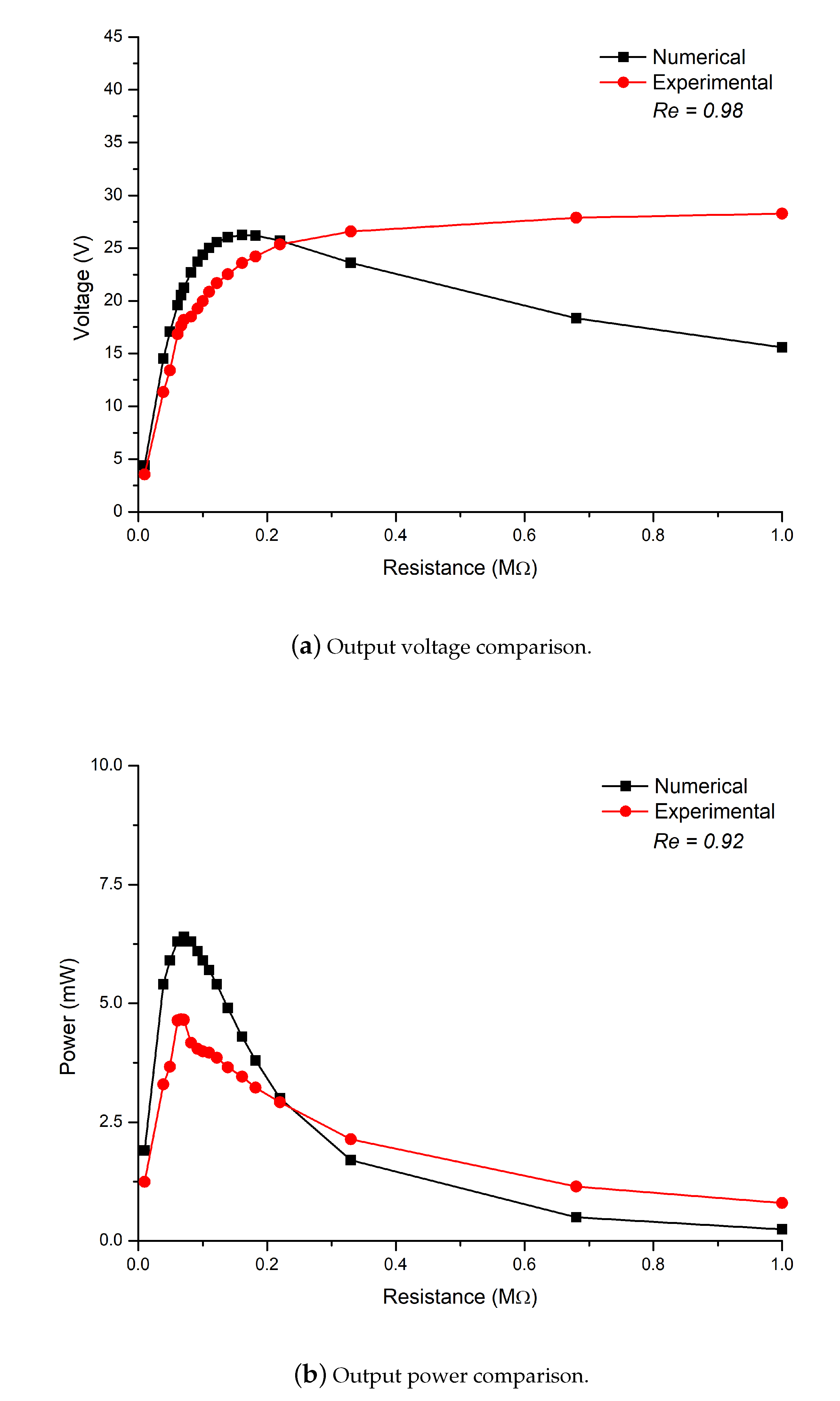
4.1. Energy Harvesting
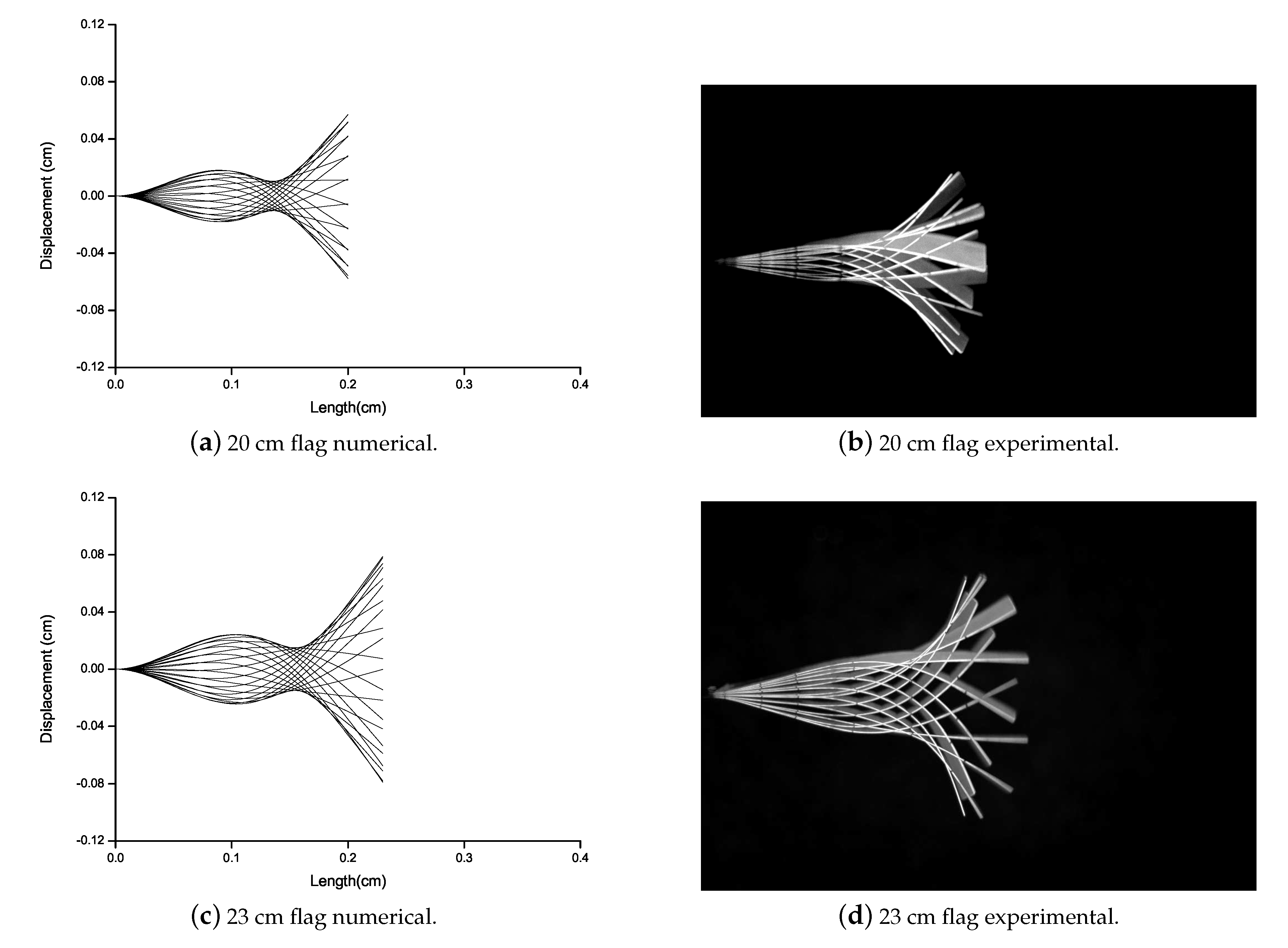
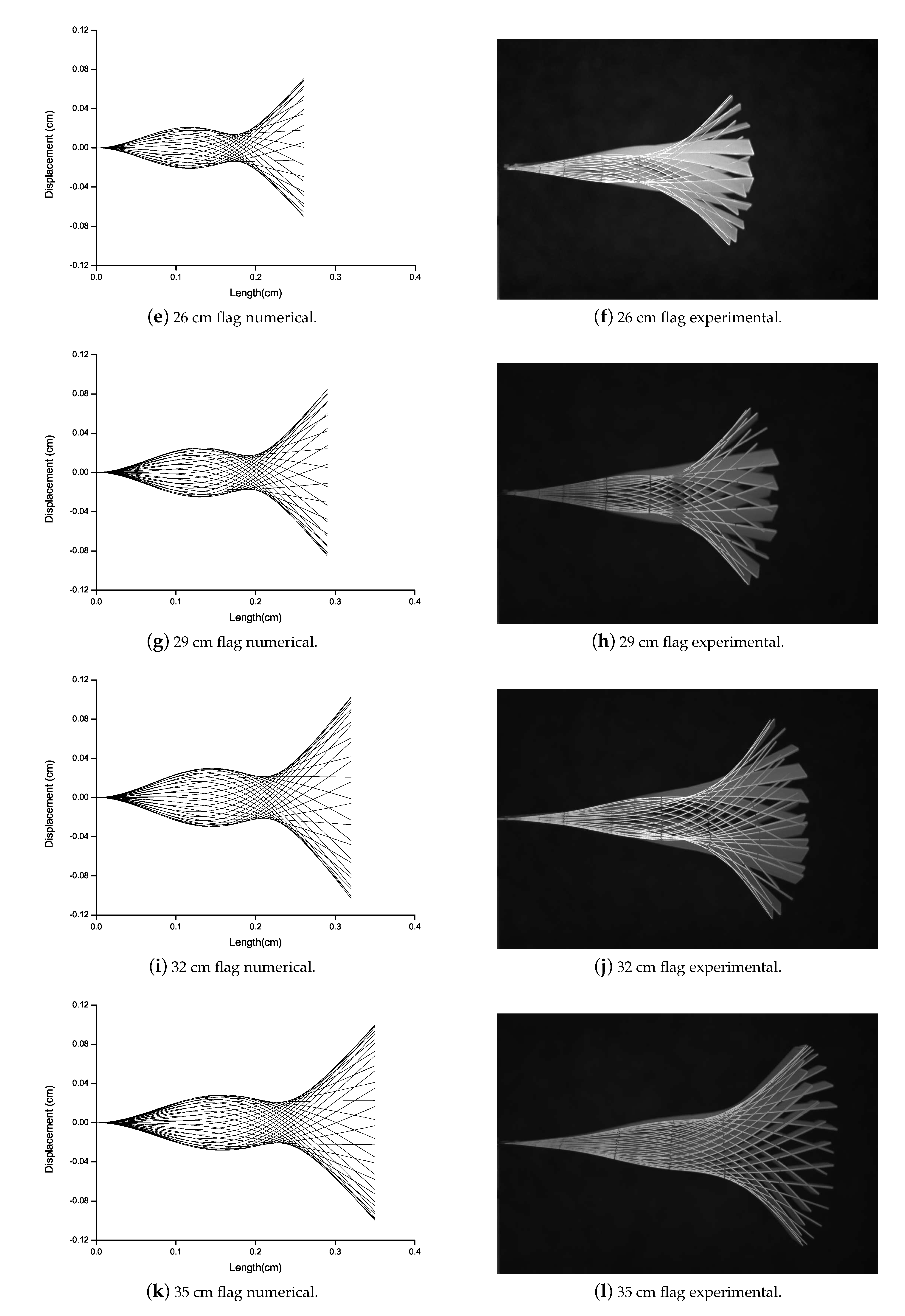
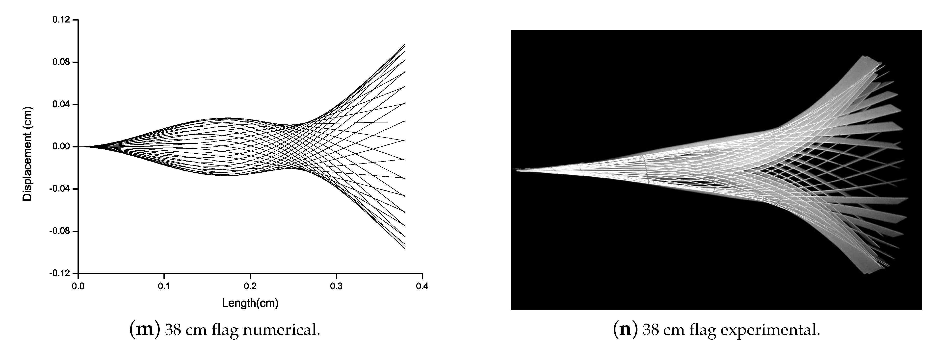
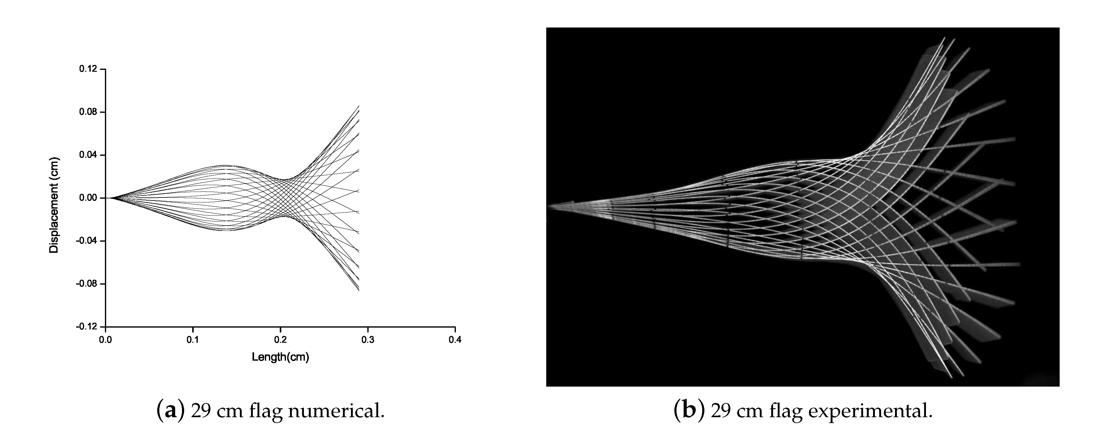
4.2. Flutter Vibration Mode
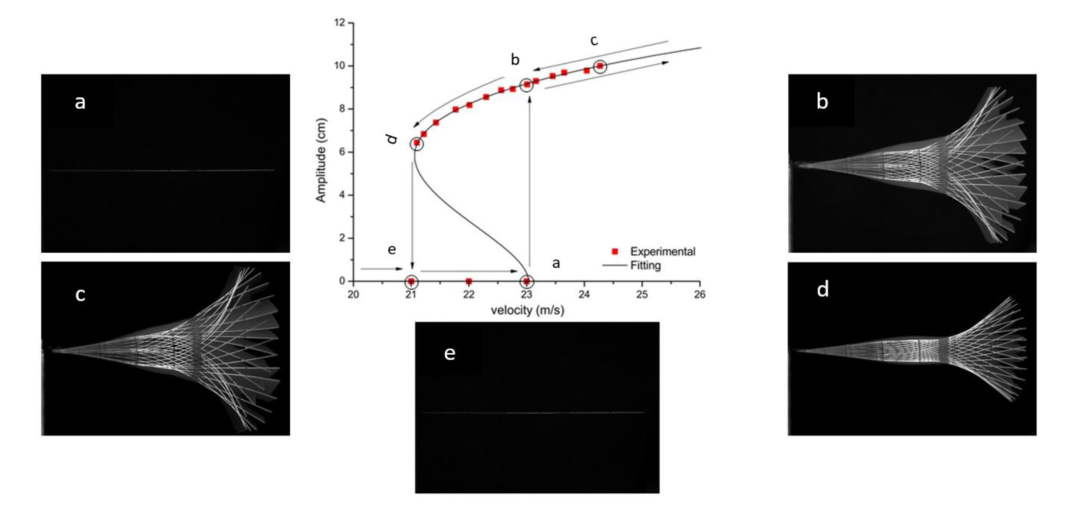
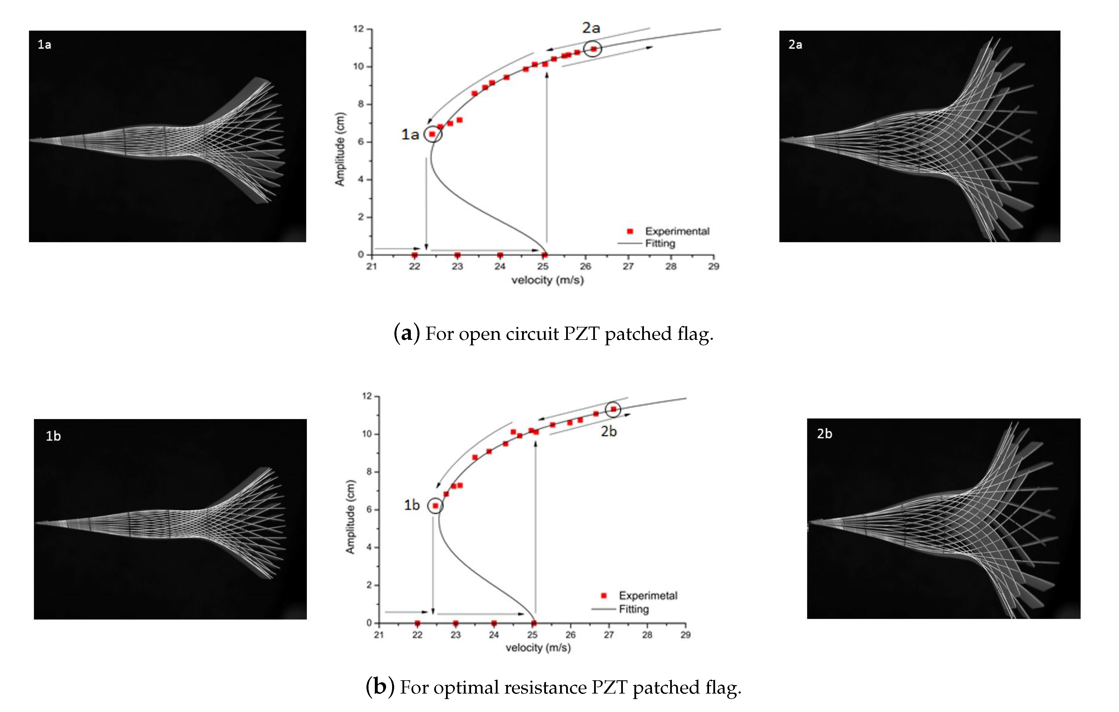
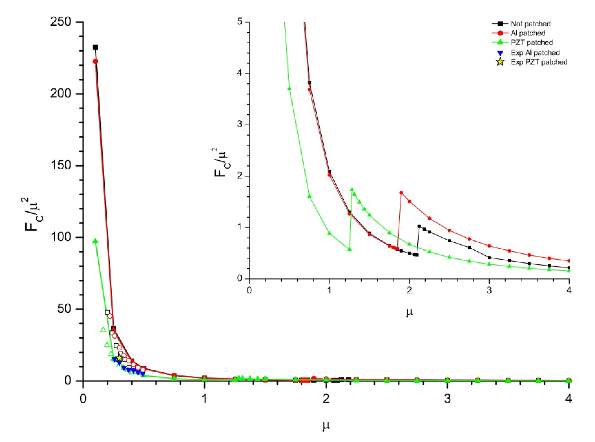
4.3. Bifurcation Analysis
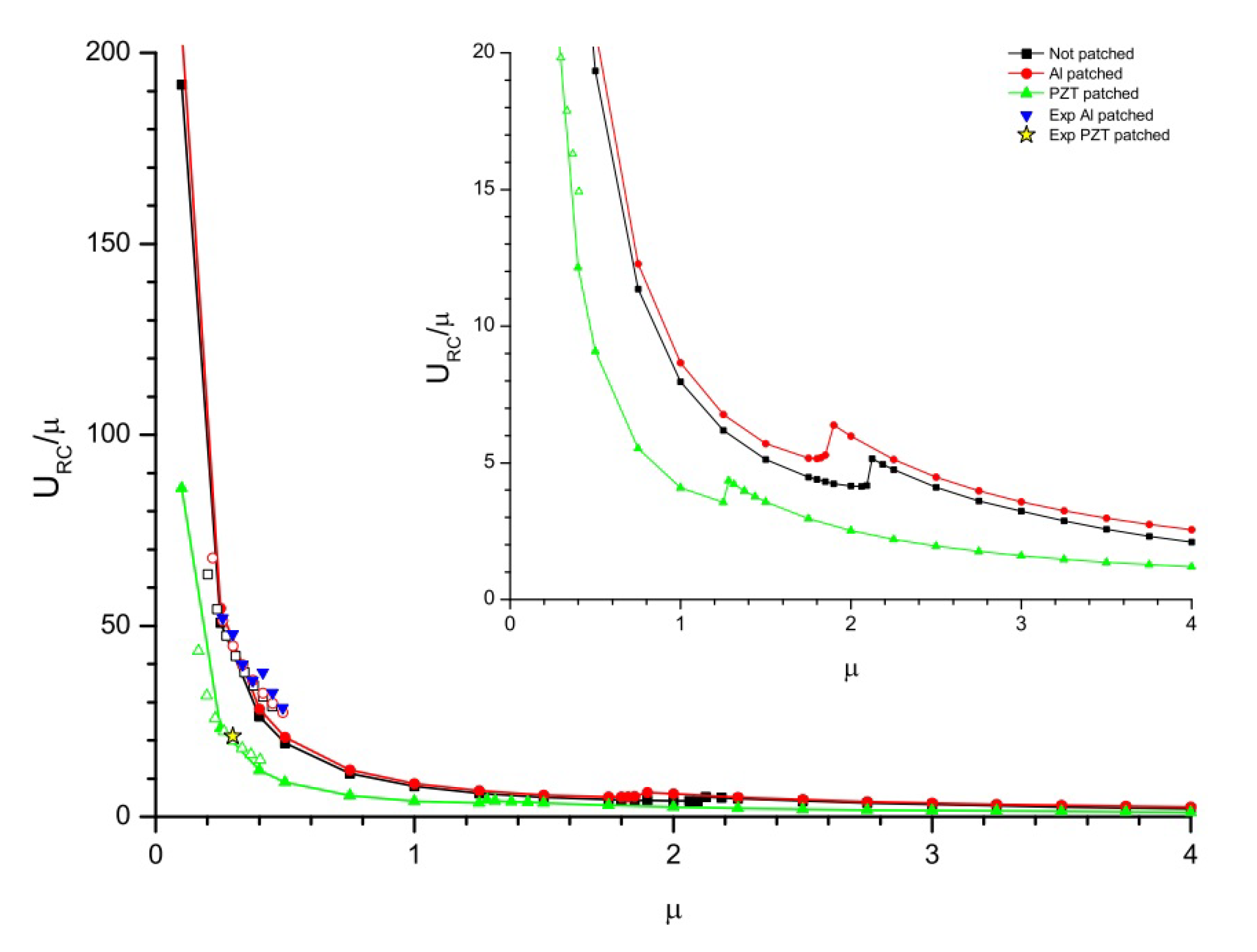
4.4. Flutter Boundary Conditions
5. Conclusions
Author Contributions
Funding
Conflicts of Interest
Abbreviations
| A | Flag Tip Amplitude |
| Aluminium | |
| Piezoelectric Inherent Capacitance | |
| d | Piezoelectric Patch Width |
| Piezoelectric Constant in 31 Coupling Direction | |
| Critical Frequency | |
| Reduced Critical Frequency | |
| Fluid-Structure Interaction | |
| h | Flag Thickness |
| Electro-mechanical Coupling Factor | |
| L | Length of Flag |
| Limit Cycle Oscillations | |
| Piezoelectric Aeroelastic Energy Harvesting | |
| Piezoelectric Energy Harvesting | |
| Piezoelectric | |
| q | Electrical Charge |
| R | External Resistance |
| Critical Flow Velocity | |
| Reduced Critical Velocity | |
| V | Electric Potential |
| Mass Ratio | |
| Density of Airflow | |
| Density of Flag | |
| Flag Tip Displacement |
References
- Gaudenzi, P. Smart Structures: Physical Behaviour, Mathematical Modelling And Applications; John Wiley & Sons: Hoboken, NJ, USA, 2009. [Google Scholar]
- Bouzelata, Y.; Kurt, E.; Uzun, Y.; Chenni, R. Mitigation of high harmonicity and design of a battery charger for a new piezoelectric wind energy harvester. Sens. Actuators A Phys. 2018, 273, 72–83. [Google Scholar] [CrossRef]
- Elahi, H. The investigation on structural health monitoring of aerospace structures via piezoelectric aeroelastic energy harvesting. Microsyst. Technol. 2020, 1–9. [Google Scholar] [CrossRef]
- Mann, B.; Sims, N. Energy harvesting from the nonlinear oscillations of magnetic levitation. J. Sound Vib. 2009, 319, 515–530. [Google Scholar] [CrossRef]
- Ferrari, M.; Ferrari, V.; Guizzetti, M.; Ando, B.; Baglio, S.; Trigona, C. Improved energy harvesting from wideband vibrations by nonlinear piezoelectric converters. Sens. Actuators A Phys. 2010, 162, 425–431. [Google Scholar] [CrossRef]
- Drezet, C.; Kacem, N.; Bouhaddi, N. Design of a nonlinear energy harvester based on high static low dynamic stiffness for low frequency random vibrations. Sens. Actuators A Phys. 2018, 283, 54–64. [Google Scholar] [CrossRef]
- Keshmiri, A.; Deng, X.; Wu, N. New energy harvester with embedded piezoelectric stacks. Compos. Part B Eng. 2019, 163, 303–313. [Google Scholar] [CrossRef]
- Elahi, H.; Eugeni, M.; Gaudenzi, P.; Qayyum, F.; Swati, R.F.; Khan, H.M. Response of piezoelectric materials on thermomechanical shocking and electrical shocking for aerospace applications. Microsyst. Technol. 2018, 24, 3791–3798. [Google Scholar] [CrossRef]
- Yang, K.; Wang, J.; Yurchenko, D. A double-beam piezo-magneto-elastic wind energy harvester for improving the galloping-based energy harvesting. Appl. Phys. Lett. 2019, 115, 193901. [Google Scholar] [CrossRef]
- Wang, J.; Zhou, S.; Zhang, Z.; Yurchenko, D. High-performance piezoelectric wind energy harvester with Y-shaped attachments. Energy Convers. Manag. 2019, 181, 645–652. [Google Scholar] [CrossRef]
- Butt, Z.; Pasha, R.A.; Qayyum, F.; Anjum, Z.; Ahmad, N.; Elahi, H. Generation of electrical energy using lead zirconate titanate (PZT-5A) piezoelectric material: Analytical, numerical and experimental verifications. J. Mech. Sci. Technol. 2016, 30, 3553–3558. [Google Scholar] [CrossRef]
- Elahi, H.; Eugeni, M.; Gaudenzi, P.; Gul, M.; Swati, R.F. Piezoelectric thermo electromechanical energy harvester for reconnaissance satellite structure. Microsyst. Technol. 2019, 25, 665–672. [Google Scholar] [CrossRef]
- Elahi, H.; Israr, A.; Swati, R.; Khan, H.; Tamoor, A. Stability of piezoelectric material for suspension applications. In Proceedings of the 2017 Fifth International Conference on Aerospace Science & Engineering (ICASE), Islamabad, Pakistan, 14–16 November 2017; pp. 1–5. [Google Scholar]
- Mahmoudi, S.; Kacem, N.; Bouhaddi, N. Enhancement of the performance of a hybrid nonlinear vibration energy harvester based on piezoelectric and electromagnetic transductions. Smart Mater. Struct. 2014, 23, 075024. [Google Scholar] [CrossRef]
- Strutt, J.W.; Rayleigh, L. On the instability of jets. Proc. Lond. Math. Soc. 1878, 10, 4–13. [Google Scholar]
- Watanabe, Y.; Suzuki, S.; Sugihara, M.; Sueoka, Y. An experimental study of paper flutter. J. Fluids Struct. 2002, 16, 529–542. [Google Scholar] [CrossRef]
- Huang, L. Flutter of cantilevered plates in axial flow. J. Fluids Struct. 1995, 9, 127–147. [Google Scholar] [CrossRef]
- Doaré, O.; Michelin, S. Piezoelectric coupling in energy-harvesting fluttering flexible plates: Linear stability analysis and conversion efficiency. J. Fluids Struct. 2011, 27, 1357–1375. [Google Scholar] [CrossRef]
- Shen, L.; Zhang, X.; Yue, D.K.; Triantafyllou, M.S. Turbulent flow over a flexible wall undergoing a streamwise travelling wave motion. J. Fluid Mech. 2003, 484, 197–221. [Google Scholar] [CrossRef]
- Liao, J.C.; Beal, D.N.; Lauder, G.V.; Triantafyllou, M.S. Fish exploiting vortices decrease muscle activity. Science 2003, 302, 1566–1569. [Google Scholar] [CrossRef]
- Paidoussis, M.P. Fluid-Structure Interactions: Slender Structures and Axial Flow; Academic Press: Cambridge, MA, USA, 1998; Volume 1. [Google Scholar]
- Argentina, M.; Mahadevan, L. Fluid-flow-induced flutter of a flag. Proc. Natl. Acad. Sci. USA 2005, 102, 1829–1834. [Google Scholar] [CrossRef]
- Manela, A.; Howe, M.S. The forced motion of a flag. J. Fluid Mech. 2009, 635, 439–454. [Google Scholar] [CrossRef]
- Alben, S. Optimal flexibility of a flapping appendage in an inviscid fluid. J. Fluid Mech. 2008, 614, 355–380. [Google Scholar] [CrossRef]
- Michelin, S.; Smith, S.G.L.; Glover, B.J. Vortex shedding model of a flapping flag. J. Fluid Mech. 2008, 617, 1–10. [Google Scholar] [CrossRef]
- Peskin, C.S. The immersed boundary method. Acta Numer. 2002, 11, 479–517. [Google Scholar] [CrossRef]
- Kim, Y.; Peskin, C.S. Penalty immersed boundary method for an elastic boundary with mass. Phys. Fluids 2007, 19, 053103. [Google Scholar] [CrossRef]
- Masoud, H.; Alexeev, A. Resonance of flexible flapping wings at low Reynolds number. Phys. Rev. E 2010, 81, 056304. [Google Scholar] [CrossRef]
- Taneda, S. Waving motions of flags. J. Phys. Soc. Jpn. 1968, 24, 392–401. [Google Scholar] [CrossRef]
- Zhang, J.; Childress, S.; Libchaber, A.; Shelley, M. Flexible filaments in a flowing soap film as a model for one-dimensional flags in a two-dimensional wind. Nature 2000, 408, 835–839. [Google Scholar] [CrossRef]
- Tang, D.; Yamamoto, H.; Dowell, E. Flutter and limit cycle oscillations of two-dimensional panels in three-dimensional axial flow. J. Fluids Struct. 2003, 17, 225–242. [Google Scholar] [CrossRef]
- Tang, L.; Paı, M.P. On the instability and the post-critical behaviour of two-dimensional cantilevered flexible plates in axial flow. J. Sound Vib. 2007, 305, 97–115. [Google Scholar] [CrossRef]
- Doar, O.; Sauzade, M.; Eloy, C. Flutter of an elastic plate in a channel flow: Confinement and finite-size effects. J. Fluids Struct. 2011, 27, 76–88. [Google Scholar]
- Sanches, L.; Guimarães, T.A.; Marques, F.D. Aeroelastic tailoring of nonlinear typical section using the method of multiple scales to predict post-flutter stable LCOs. Aerosp. Sci. Technol. 2019, 90, 157–168. [Google Scholar] [CrossRef]
- Elahi, H.; Eugeni, M.; Gaudenzi, P. A review on mechanisms for piezoelectric-based energy harvesters. Energies 2018, 11, 1850. [Google Scholar] [CrossRef]
- Abdelkefi, A. Aeroelastic energy harvesting: A review. Int. J. Eng. Sci. 2016, 100, 112–135. [Google Scholar] [CrossRef]
- Elvin, N.G.; Elvin, A.A. The flutter response of a piezoelectrically damped cantilever pipe. J. Intell. Mater. Syst. Struct. 2009, 20, 2017–2026. [Google Scholar] [CrossRef]
- Theodorsen, T.; Mutchler, W. General Theory of Aerodynamic Instability and the Mechanism of Flutter; NACA: Langley Field, VA, USA, 1935. [Google Scholar]
- Beran, P.S.; Strganac, T.W.; Kim, K.; Nichkawde, C. Studies of store-induced limit-cycle oscillations using a model with full system nonlinearities. Nonlinear Dyn. 2004, 37, 323–339. [Google Scholar] [CrossRef]
- Muturi, N.; Spies, A.C.; Bender, K.; Lee, C.L. Stall Flutter Oscillation Measurements from a Two Degree-of-Freedom Airfoil with Nonlinear Stiffness. In Proceedings of the 54th AIAA/ASME/ASCE/AHS/ASC Structures, Structural Dynamics, and Materials Conference, Boston, MA, USA, 8–11 April 2013; p. 1842. [Google Scholar]
- Elahi, H.; Eugeni, M.; Gaudenzi, P. Design and performance evaluation of a piezoelectric aeroelastic energy harvester based on the limit cycle oscillation phenomenon. Acta Astronaut. 2019, 157, 233–240. [Google Scholar] [CrossRef]
- Eugeni, M.; Elahi, H.; Fune, F.; Lampani, L.; Mastroddi, F.; Romano, G.P.; Gaudenzi, P. Numerical and experimental investigation of piezoelectric energy harvester based on flag-flutter. Aerosp. Sci. Technol. 2020, 97, 105634. [Google Scholar] [CrossRef]
Publisher‘s Note: MDPI stays neutral with regard to jurisdictional claims in published maps and institutional affiliations. |


| Type of PZT | PZT Layer(s) | Output Power (mW) |
|---|---|---|
| PZT-5A | 1 | 0.003 |
| PSI-5A4E | 1 | 0.2 |
| QP 10N | 2 | 2.2 |
| Material | Length | Width | Thickness |
|---|---|---|---|
| Piezoelectric patch | 6.1 | 3.5 | 0.01 |
| Fibreglass | 15:3:38 | 6 | 0.05 |
| Aluminium patch | 5 | 3 | 0.01 |
| Properties (unit) | Symbol | Glass Fiber | PIC 255 |
|---|---|---|---|
| Young’s Modulus (GPa) | 21.49 | 62.1 | |
| 10 | 48.3 | ||
| Shear Modulus (GPa) | 4 | 23.5 | |
| 4 | 21 | ||
| Poisson’s Ratio | 0.2 | 0.32 | |
| 0.2 | 0.44 | ||
| Density (kg/m) | 1900 | 7800 |
| Geometry | Nodes | Elements |
|---|---|---|
| PZT patch | 465 | 420 |
| Al patch | 273 | 240 |
| PIC 255 | 273 | 240 |
| Kapton layers | 261 | 180 |
| Flag (Total) | 1765 (17 cm) to 2625 (38 cm) | 1344 (17 cm) to 2496 (38 cm) |
| Length | Width | Thickness | |
|---|---|---|---|
| Al patched flag | 15:3:38 | 6 | 0.05 |
| PZT patched flag | 29 | 6 | 0.05 |
© 2020 by the authors. Licensee MDPI, Basel, Switzerland. This article is an open access article distributed under the terms and conditions of the Creative Commons Attribution (CC BY) license (http://creativecommons.org/licenses/by/4.0/).
Share and Cite
Elahi, H.; Eugeni, M.; Fune, F.; Lampani, L.; Mastroddi, F.; Paolo Romano, G.; Gaudenzi, P. Performance Evaluation of a Piezoelectric Energy Harvester Based on Flag-Flutter. Micromachines 2020, 11, 933. https://doi.org/10.3390/mi11100933
Elahi H, Eugeni M, Fune F, Lampani L, Mastroddi F, Paolo Romano G, Gaudenzi P. Performance Evaluation of a Piezoelectric Energy Harvester Based on Flag-Flutter. Micromachines. 2020; 11(10):933. https://doi.org/10.3390/mi11100933
Chicago/Turabian StyleElahi, Hassan, Marco Eugeni, Federico Fune, Luca Lampani, Franco Mastroddi, Giovanni Paolo Romano, and Paolo Gaudenzi. 2020. "Performance Evaluation of a Piezoelectric Energy Harvester Based on Flag-Flutter" Micromachines 11, no. 10: 933. https://doi.org/10.3390/mi11100933
APA StyleElahi, H., Eugeni, M., Fune, F., Lampani, L., Mastroddi, F., Paolo Romano, G., & Gaudenzi, P. (2020). Performance Evaluation of a Piezoelectric Energy Harvester Based on Flag-Flutter. Micromachines, 11(10), 933. https://doi.org/10.3390/mi11100933