The Modelling, Analysis, and Experimental Validation of a Novel Micro-Robot for Diagnosis of Intestinal Diseases

Abstract
1. Introduction
2. Materials and Methods
2.1. Mechanisms Design
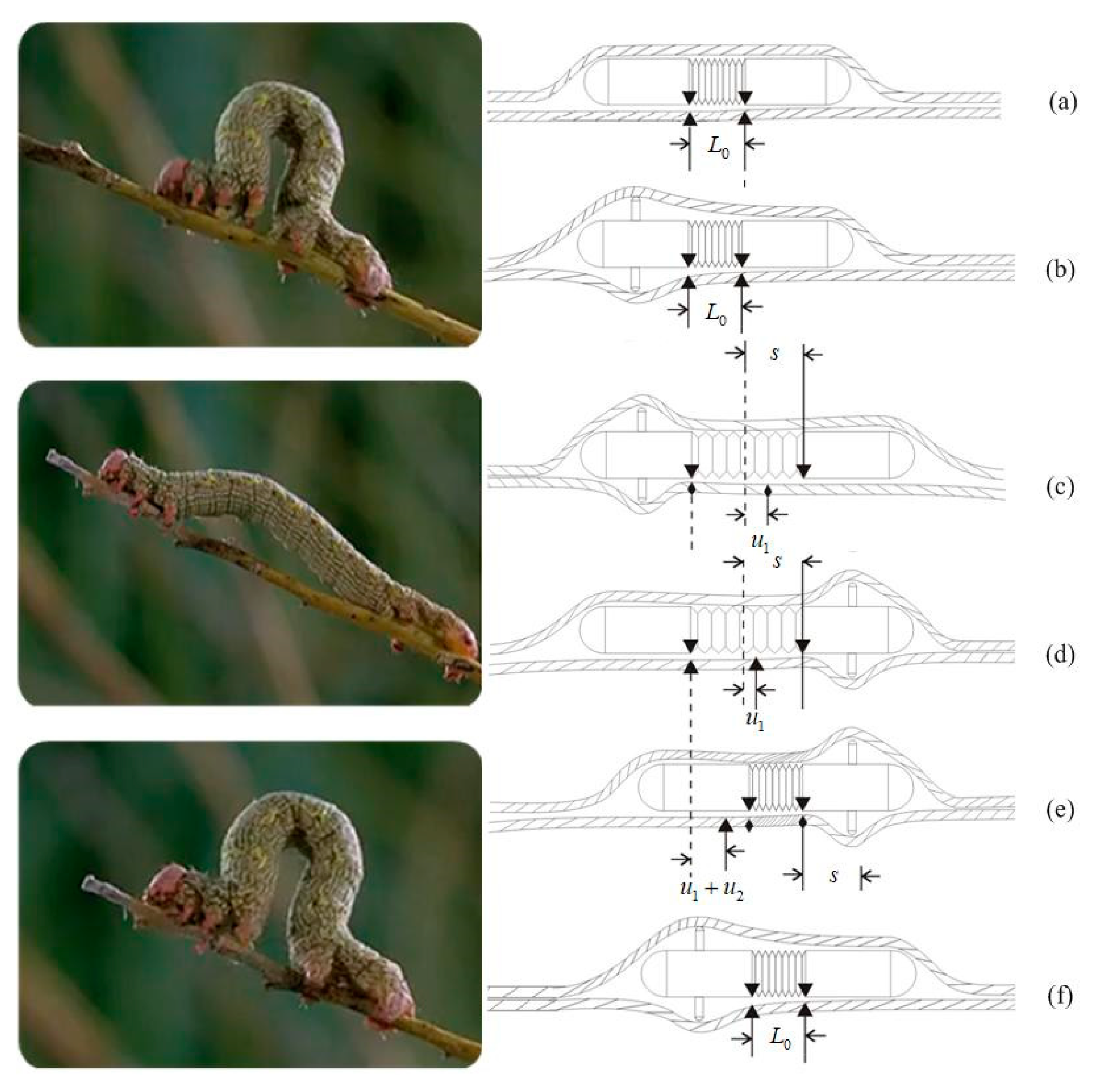
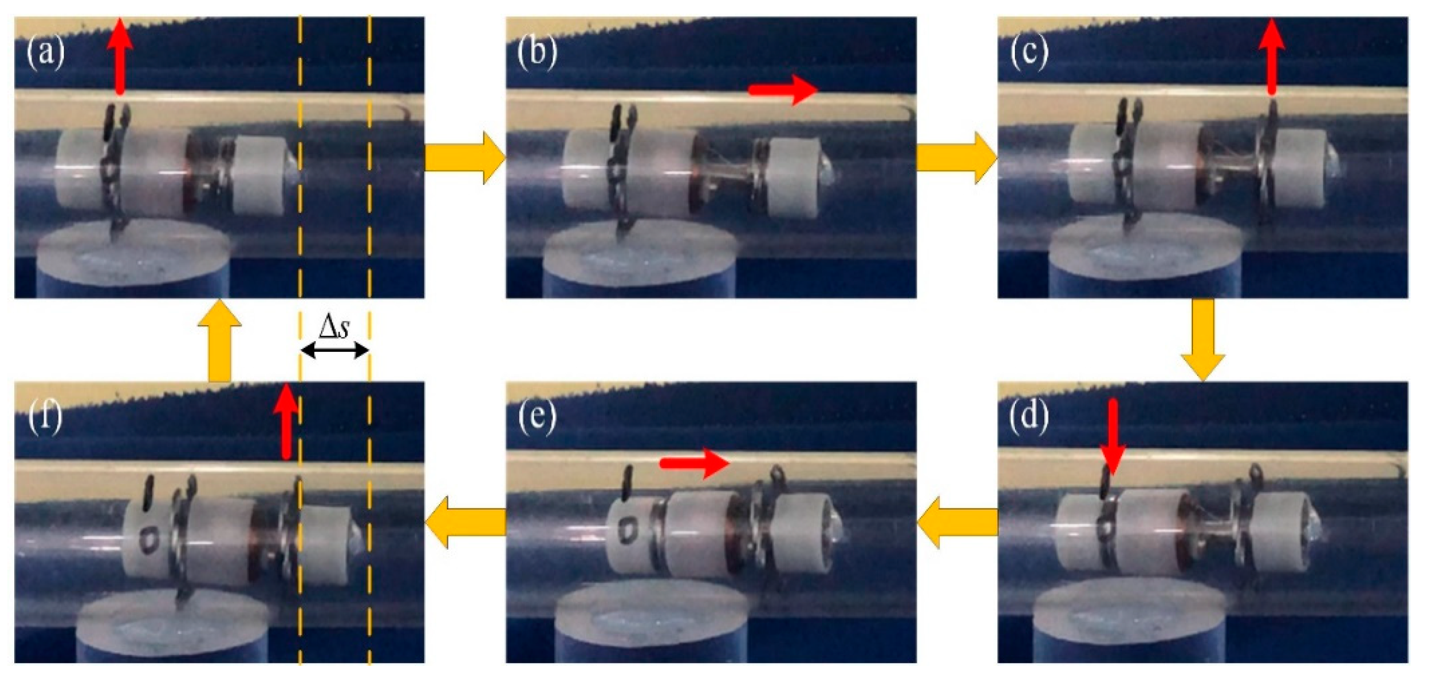
2.1.1. Locomotion Principle of the IIMR
- Since the pyloric ostium is the narrowest part of the digestive tract, with a diameter of about 15 mm [22], the size of the micro-robot should be as small as possible: no more than 15 mm.
- A large variable diameter ratio (the ratio of the maximum expansion diameter to the minimum contraction diameter of a radial expanding mechanism) is needed to adapt different diameters at different parts of the intestine, as presented in Figure 1b.
- The speed of one step is determined by the maximum extended length (shown in Figure 1c). Thus, the optimal motor and compact reducer should be chosen to obtain a large extended length.
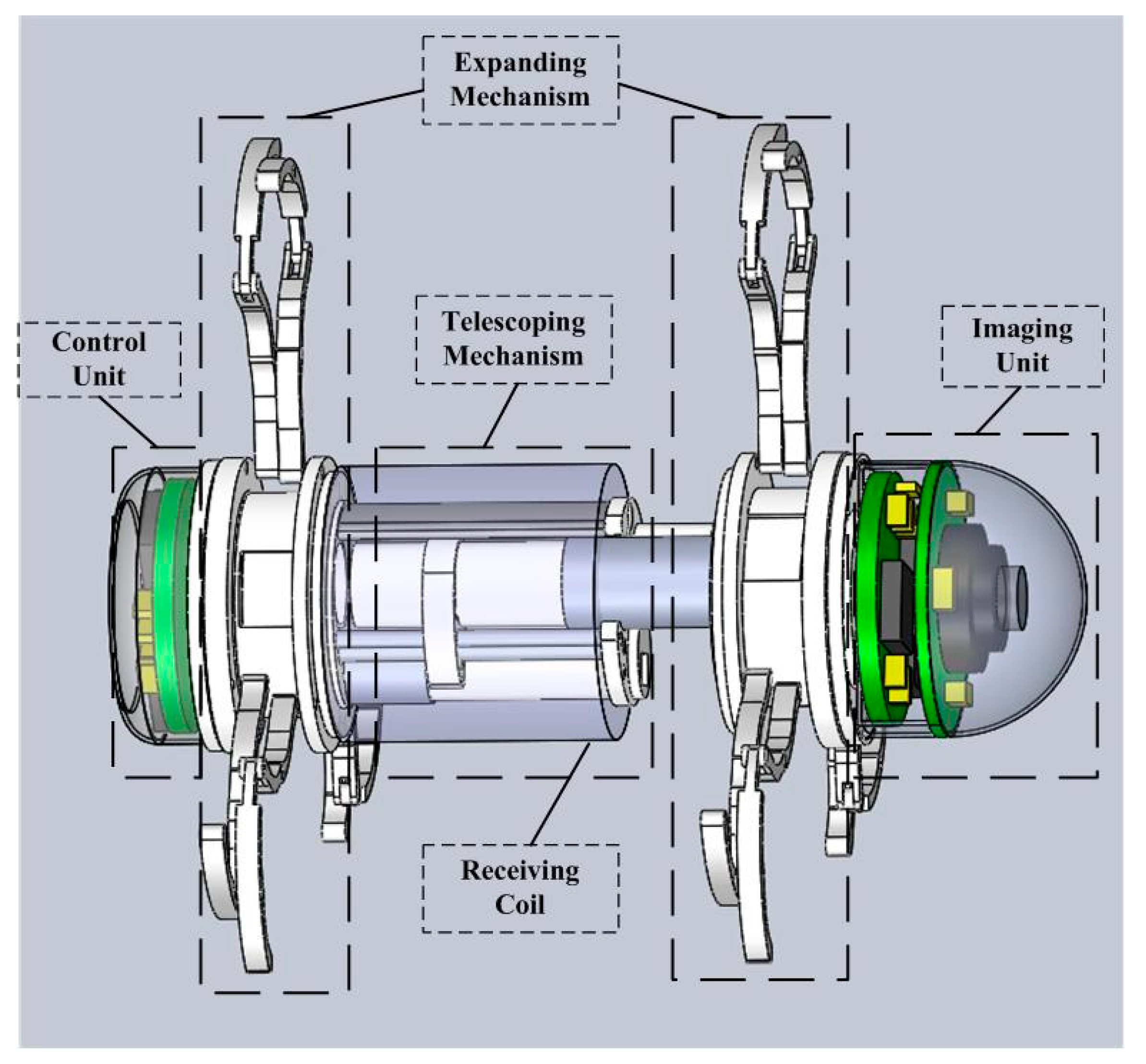
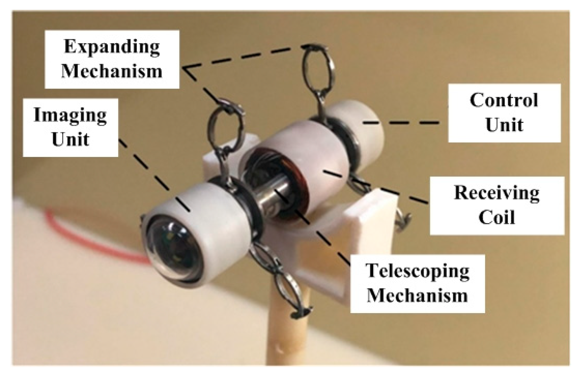
2.1.2. System Review
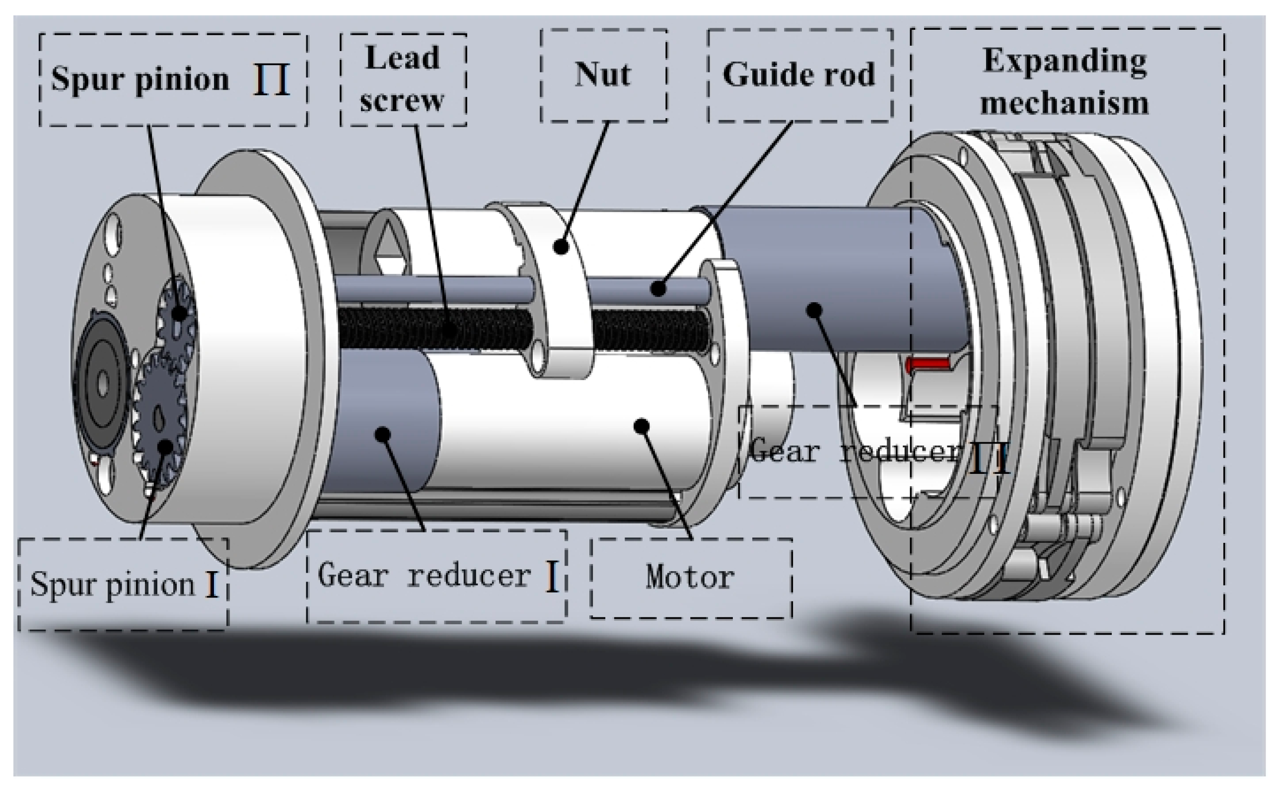
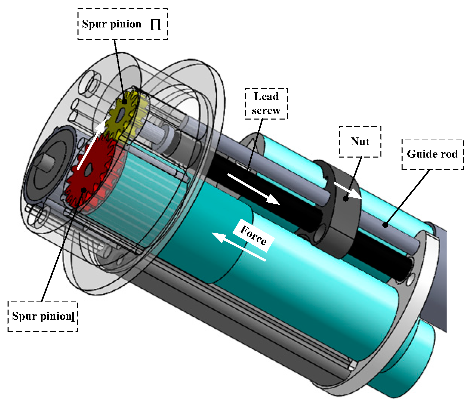
2.1.3. Telescoping Mechanism Design
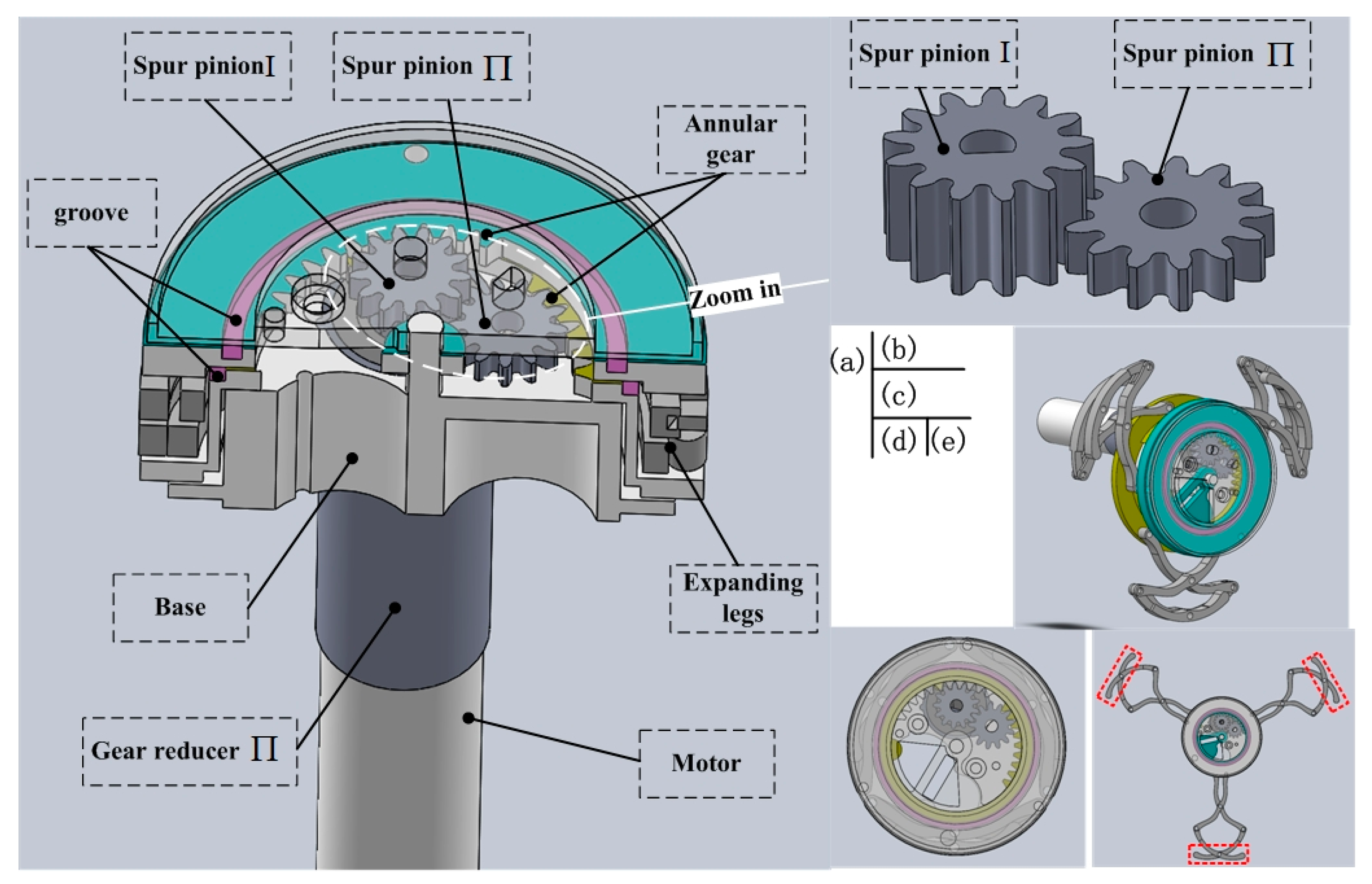
2.1.4. Expanding Mechanism Design
2.2. Kinematics and Dynamics Analysis of the IIMR System
2.2.1. Telescoping Mechanism Analysis
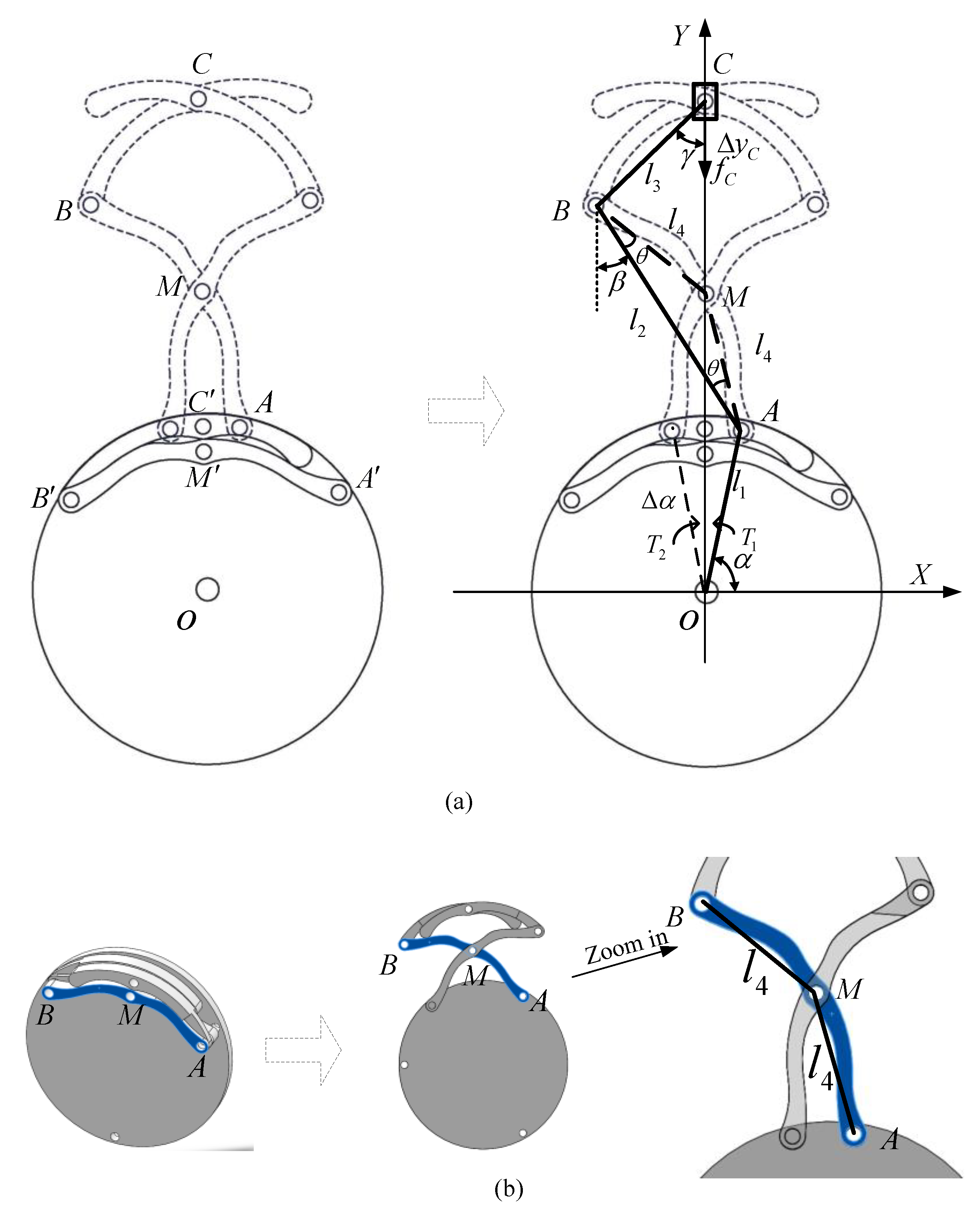
2.2.2. Expanding Mechanism Analysis
Kinematics Analysis
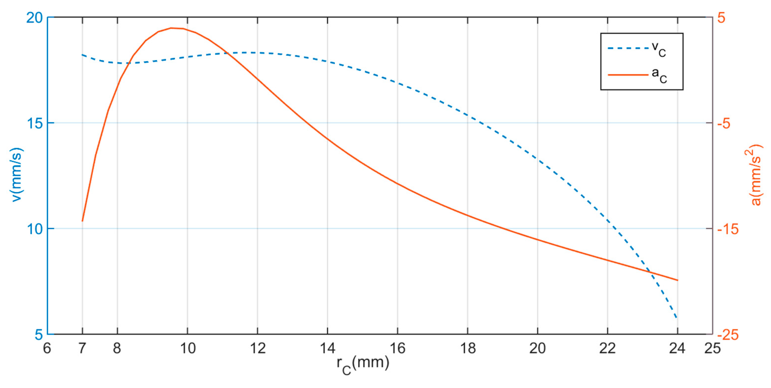
Dynamics Analysis
3. Experimental Validation and Results
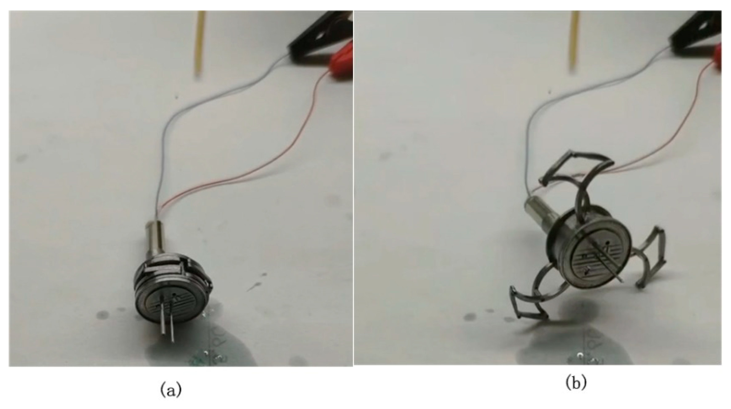
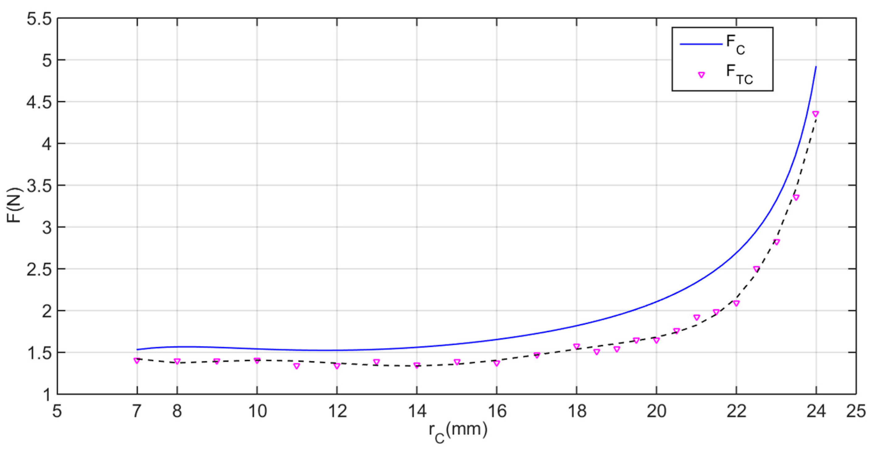
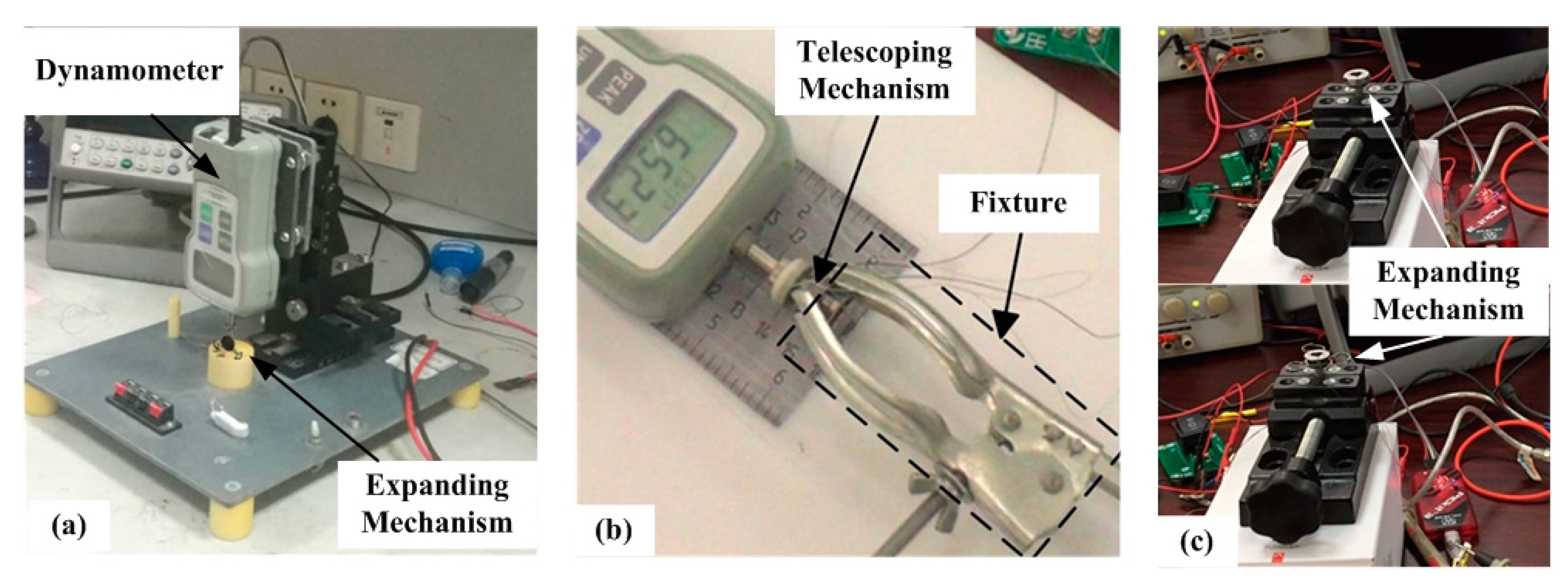
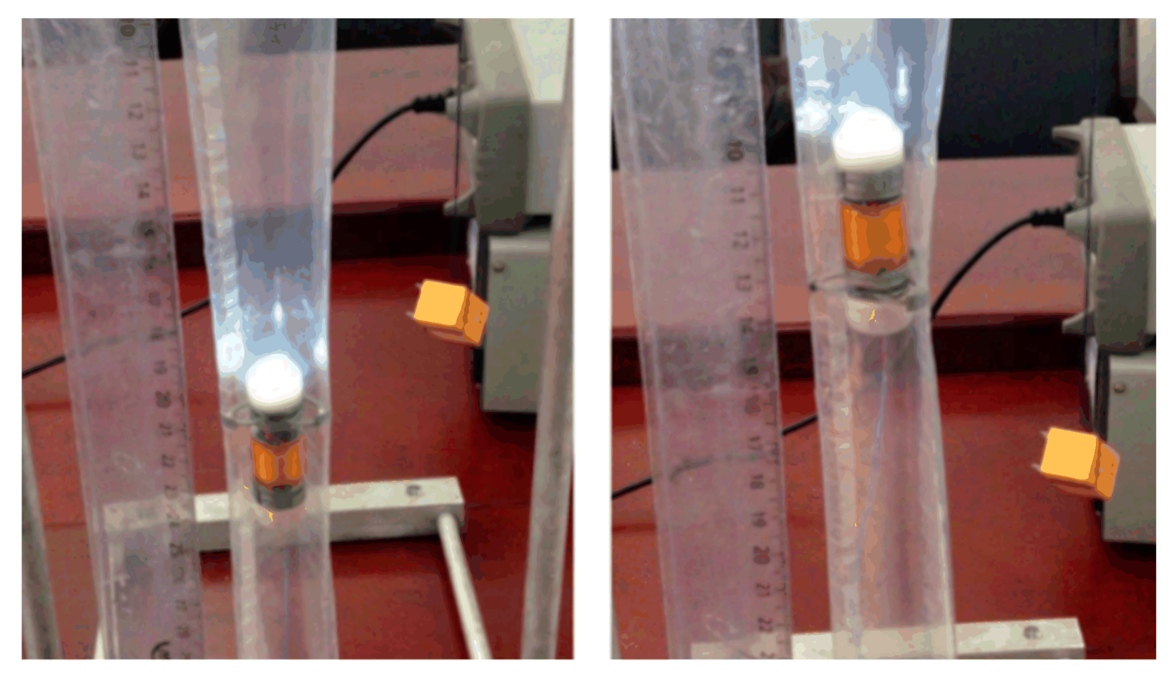
3.1. Force Test and Locomotion Test
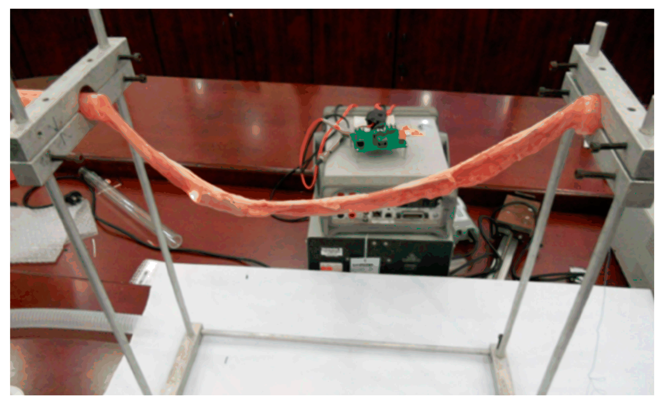
3.2. In Vitro Experiments
4. Discussion and Conclusions
Author Contributions
Funding
Acknowledgments
Conflicts of Interest
Nomenclature
| Symbols | Definitions |
Appendix A
References
- Siegel, R.L.; Miller, K.D.; Jemal, A. Cancer statistics, 2019. CA Cancer J. Clin. 2019, 69, 7–34. [Google Scholar] [PubMed]
- Feng, R.-M.; Zong, Y.-N.; Cao, S.-M.; Xu, R. Current cancer situation in China: Good or bad news from the 2018 Global Cancer Statistics? Cancer Commun. 2019, 39, 22. [Google Scholar] [CrossRef]
- Ruan, M.; Ren, Y.; Wu, Z.; Wu, J.; Wang, S.; Yang, X. The Survey of CNN-based Cancer Diagnosis System. IOP Conf. Ser. Mater. Sci. Eng. 2018, 466, 012095. [Google Scholar] [CrossRef]
- Stein, D.J.; Shaker, R. Complications of upper gastrointestinal endoscopy. Gastrointest. Emerg. 2016, 16, 43–50. [Google Scholar] [CrossRef]
- Gao, J. Researches on Key Technologies and Related Experiments of Micro-Bionic Robots for Inspecting the Intestines. Ph.D. Thesis, Shanghai Jiao Tong University, Shanghai, China, 2017. [Google Scholar]
- Iddan, G.; Meron, G.; Glukhovsky, A.; Swain, P. Wireless capsule endoscopy. Nature 2000, 405, 417. [Google Scholar] [CrossRef]
- Kjellberg, A.; Nyström, H.; Söderberg, M.; Dlugosz, A.; Jörnvall, H.; Steinberg, A. Massive air embolism as a complication of upper gastrointestinal endoscopy: A case report illustrating a stroke mimic, literature review, and suggested management. Clin. Case Rep. 2018, 6, 1862–1867. [Google Scholar] [CrossRef]
- Yim, S.; Sitti, M. Design and rolling locomotion of a magnetically actuated soft capsule endoscope. IEEE Trans. Robot. 2011, 28, 183–194. [Google Scholar] [CrossRef]
- Son, D.; Dogan, M.D.; Sitti, M. Magnetically Actuated Soft Capsule Endoscope for Fine-Needle Aspiration Biopsy. In Proceedings of the 2017 IEEE International Conference on Robotics and Automation (ICRA), Singapore, 29 May–3 June 2017; pp. 1132–1139. [Google Scholar]
- Taddese, A.Z.; Slawinski, P.R.; Pirotta, M.; De Momi, E.; Obstein, K.L.; Valdastri, P. Enhanced real-time pose estimation for closed-loop robotic manipulation of magnetically actuated capsule endoscopes. Int. J. Robot. Res. 2018, 37, 890–911. [Google Scholar] [CrossRef]
- Bianchi, F.; Masaracchia, A.; Barjuei, E.S.; Menciassi, A.; Arezzo, A.; Koulaouzidis, A.; Stoyanov, D.; Dario, P.; Ciuti, G. Localization strategies for robotic endoscopic capsules: A review. Expert Rev. Med. Devices 2019, 16, 381–403. [Google Scholar] [CrossRef]
- Prendergast, J.M.; Formosa, G.; Rentschler, M.E. A platform for developing robotic navigation strategies in a deformable, dynamic environment. IEEE Robot. Autom. Lett. 2018, 3, 2670–2677. [Google Scholar] [CrossRef]
- Quirini, M.; Menciassi, A.; Scapellato, S.; Stefanini, C.; Dario, P. Design and fabrication of a motor legged capsule for the active exploration of the gastrointestinal tract. IEEE/ASME Trans. Mechatron. 2008, 13, 169–179. [Google Scholar] [CrossRef]
- Slawinski, P.R.; Obstein, K.L.; Valdastri, P. Emerging issues and future developments in capsule endoscopy. Tech. Gastrointest. Endosc. 2015, 17, 40–46. [Google Scholar] [CrossRef]
- Singeap, A.-M.; Stanciu, C.; Trifan, A. Capsule endoscopy: The road ahead. World J. Gastroenterol. 2016, 22, 369–378. [Google Scholar] [CrossRef]
- Costarides, V.; Zygomalas, A.; Giokas, K.; Koutsouris, D. Robotics in Surgical Techniques: Present and Future Trends. In Design, Development, and Integration of Reliable Electronic Healthcare Platforms; IGI Global: Hershey, PA, USA, 2017; pp. 86–100. [Google Scholar]
- Kim, H.M.; Yang, S.; Kim, J.S.; Park, S.; Cho, J.H.; Park, J.Y.; Kim, T.S.; Yoon, E.-S.; Song, S.Y.; Bang, S. Active locomotion of a paddling-based capsule endoscope in an in vitro and in vivo experiment (with videos). Gastrointest. Endosc. 2010, 72, 381–387. [Google Scholar] [CrossRef] [PubMed]
- Kwack, W.G.; Lim, Y.J. Current status and research into overcoming limitations of capsule endoscopy. Clin. Endosc. 2016, 49, 8–15. [Google Scholar] [CrossRef] [PubMed]
- Sliker, L.J.; Kern, M.D.; Rentschler, M.E. An automated traction measurement platform and empirical model for evaluation of rolling micro patterned wheels. IEEE/ASME Trans. Mechatron. 2014, 20, 1854–1862. [Google Scholar] [CrossRef]
- Prendergast, J.M.; Rentschler, M.E. Towards autonomous motion control in minimally invasive robotic surgery. Expert Rev. Med. Devices 2016, 13, 741–748. [Google Scholar] [CrossRef]
- Gao, J.; Yan, G.; Zhang, Z. Design and Implementation of a Clamper-Based and Motor-Driven Capsule Robot Powered by Wireless Power Transmission. IEEE Access 2019, 7, 138151–138161. [Google Scholar] [CrossRef]
- Ke, Q. The Research of a Micro Robot System for Intestinal Diseases Diagnoses and Its Wireless Power Transmission Technology. Ph.D. Thesis, Shanghai Jiao Tong University, Shanghai, China, 2017. [Google Scholar]
- Wang, W.; Yan, G.; Wang, Z.; Jiang, P.; Meng, Y.; Chen, F.; Xue, R. A Novel Expanding Mechanism of Gastrointestinal Microrobot: Design, Analysis and Optimization. Micromachines 2019, 10, 724. [Google Scholar] [CrossRef]
- Pu, P.; Yan, G.; Wang, Z.; Han, D. Design and Experiment of Expanding Mechanism and Power Receiving Coil for Micro Intestinal Robot. J. Shanghai Jiao Tong Univ. 2019, 53, 1143–1150. [Google Scholar]
- Simi, M.; Valdastri, P.; Quaglia, C.; Menciassi, A.; Dario, P. Design, fabrication, and testing of a capsule with hybrid locomotion for gastrointestinal tract exploration. IEEE/ASME Trans. Mechatron. 2010, 15, 170–180. [Google Scholar] [CrossRef]
- Gao, J.; Yan, G.; He, S.; Xu, F.; Wang, Z. Design, analysis, and testing of a motor-driven capsule robot based on a sliding clamper. Robotica 2015, 35, 521–536. [Google Scholar] [CrossRef]
- Woods, S.P. Wireless Capsule Endoscope for Targeted Drug Delivery. Ph.D. Thesis, Imperial College London, London, UK, 2016. [Google Scholar]
- Zhang, C.; Liu, H. Analytical friction model of the capsule robot in the small intestine. Tribol. Lett. 2016, 64, 39. [Google Scholar] [CrossRef]
- Carta, R.; Tortora, G.; Thoné, J.; Lenaerts, B.; Valdastri, P.; Menciassi, A.; Dario, P.; Puers, R. Wireless powering for a self-propelled and steerable endoscopic capsule for stomach inspection. Biosens. Bioelectron. 2009, 25, 845–851. [Google Scholar] [CrossRef]
- Schelstraete, W.; Devreese, M.; Croubels, S. Comparative toxicokinetics of Fusarium mycotoxins in pigs and humans. Food Chem. Toxicol. 2020, 137, 111140. [Google Scholar] [CrossRef] [PubMed]


| Parameter | Value | |
|---|---|---|
| IIMR platform (without CU & IU) | Original state | |
| Expanding mechanism | Original state | |
| Open state | ||
| Variable diameter ratio | 3.43 | |
| Telescoping mechanism | Original state | |
| Extended state | ||
| Maximum extended length |
| Motor | Size | ||
| Speed | |||
| Torque | |||
| Telescoping Mechanism | Lead screw | Nominal diameter | |
| Thread angle | |||
| Pitch | |||
| Thread length | |||
| Nut | Width | ||
| Spur pinion Ι | Modulus | ||
| Teeth number | |||
| Face width | |||
| Spur pinion Π | Modulus | ||
| Teeth number | |||
| Face width | |||
| Expanding mechanism | Spur pinion Ι | Modulus | |
| Teeth number | |||
| Face width | |||
| Spur pinion Π | Modulus | ||
| Teeth number | |||
| Face width | |||
| Annular gear | Modulus | ||
| Teeth number | |||
| Face width | |||
| Gear reducer Ι | Modulus | ||
| Total stages | |||
| Reduction ratio | |||
| Gear reducer Π | Modulus | ||
| Total stages | |||
| Reduction ratio | |||
| Telescoping Mechanism | Name | Parameters | |
|---|---|---|---|
| Lead screw | Friction angle | ||
| Helix angle | |||
| Pitch | |||
| Friction coefficient | |||
| Flank angle | |||
| Nut | Width | ||
| Transmission efficiency of each stage | |||
| Coefficient of lead screw-nut friction | |||
| Parameters | Values | Parameters | Values |
|---|---|---|---|
| /mm | 6.8 | /mm | 6.2 |
| /mm | 11.78 | /rad | 0.26 |
| /mm | 6.6 | /rad/s | 0.87 |
| 1st | 2nd | 3rd | 4th | 5th | Average | |
|---|---|---|---|---|---|---|
| Thrust (N) | 6.760 | 6.536 | 6.348 | 7.038 | 6.842 | 6.7022 |
| Extension time (s) | 2.56 | 2.84 | 3.09 | 2.90 | 2.99 | 2.876 |
| Expansion time (s) | 1.63 | 1.16 | 1.46 | 1.38 | 1.13 | 1.352 |
© 2020 by the authors. Licensee MDPI, Basel, Switzerland. This article is an open access article distributed under the terms and conditions of the Creative Commons Attribution (CC BY) license (http://creativecommons.org/licenses/by/4.0/).
Share and Cite
Han, D.; Yan, G.; Wang, Z.; Jiang, P.; Liu, D.; Zhao, K.; Ma, J. The Modelling, Analysis, and Experimental Validation of a Novel Micro-Robot for Diagnosis of Intestinal Diseases. Micromachines 2020, 11, 896. https://doi.org/10.3390/mi11100896
Han D, Yan G, Wang Z, Jiang P, Liu D, Zhao K, Ma J. The Modelling, Analysis, and Experimental Validation of a Novel Micro-Robot for Diagnosis of Intestinal Diseases. Micromachines. 2020; 11(10):896. https://doi.org/10.3390/mi11100896
Chicago/Turabian StyleHan, Ding, Guozheng Yan, Zhiwu Wang, Pingping Jiang, Dasheng Liu, Kai Zhao, and Jin Ma. 2020. "The Modelling, Analysis, and Experimental Validation of a Novel Micro-Robot for Diagnosis of Intestinal Diseases" Micromachines 11, no. 10: 896. https://doi.org/10.3390/mi11100896
APA StyleHan, D., Yan, G., Wang, Z., Jiang, P., Liu, D., Zhao, K., & Ma, J. (2020). The Modelling, Analysis, and Experimental Validation of a Novel Micro-Robot for Diagnosis of Intestinal Diseases. Micromachines, 11(10), 896. https://doi.org/10.3390/mi11100896