Design and Experimental Research of a Rotary Micro-Actuator Based on a Shearing Piezoelectric Stack

Abstract
:1. Introduction
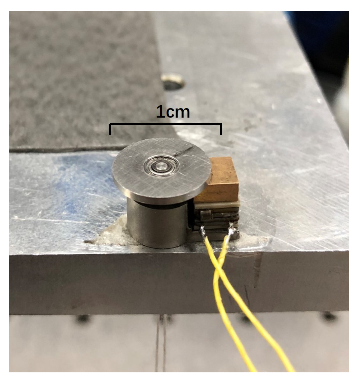
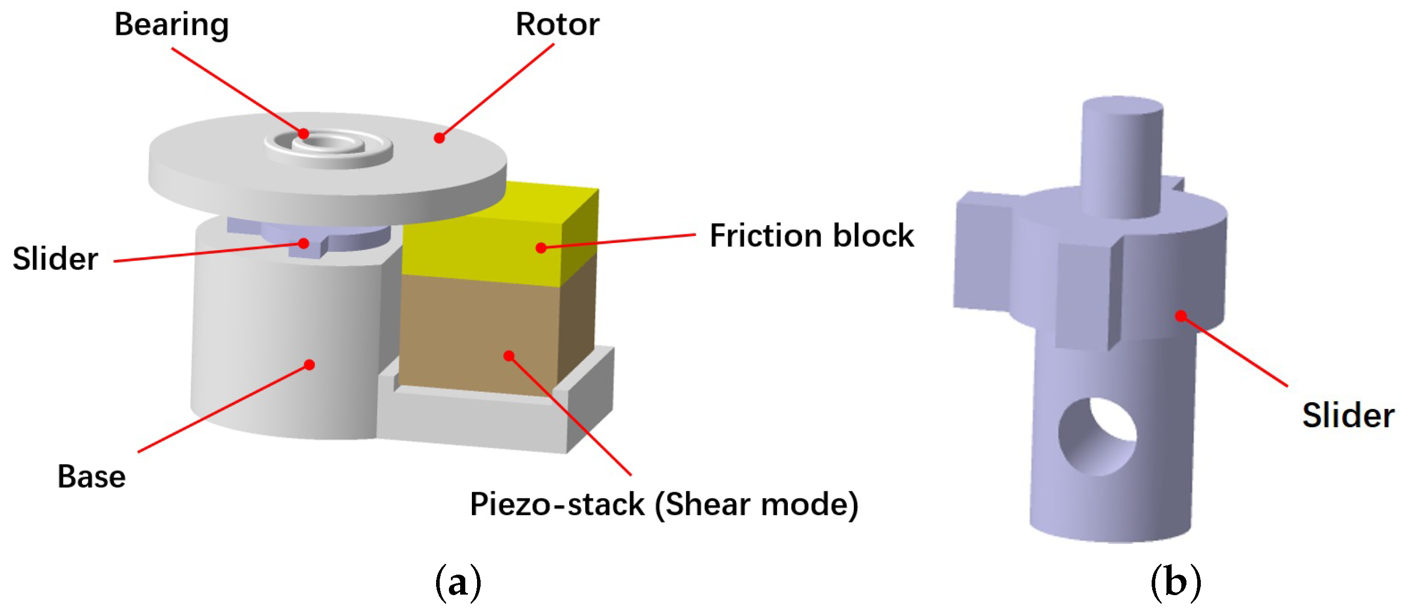
2. Structure and Operational Principle
- (1)
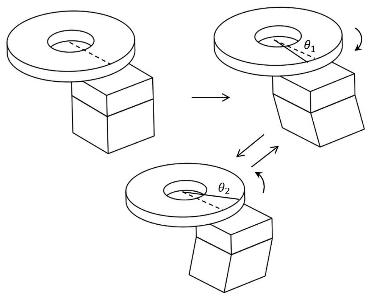
- The serrated-type voltage is not applied to the PZT stack at the beginning, and thus the PZT stack maintains the cubic shape, and the rotor remains in a static state.
- (2)
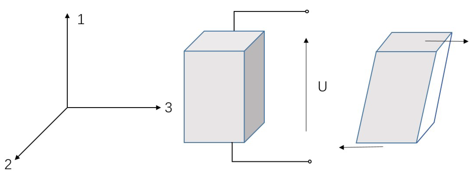
- As the serrated-type voltage is applied to the PZT stack, the voltage rapidly changes from 0 to −U (see Figure 3), and the PZT stack produces shear deformation, which leads to movement of the friction block via the dynamic friction between them. The rotor can only rotate through a small angle of along the counterclockwise direction because the response time of this step is quite short.
- (3)
- The serrated-type voltage on the PZT subsequently increases slowly from −U to U, and in this manner, the PZT stack can slowly deform along the clockwise tangential direction of the rotor. With the effects of friction between the rotor and the friction block, the rotor can rotate in the opposite direction with a rotation angle of . Thus, the total angular displacement of each cycle is written as follows:
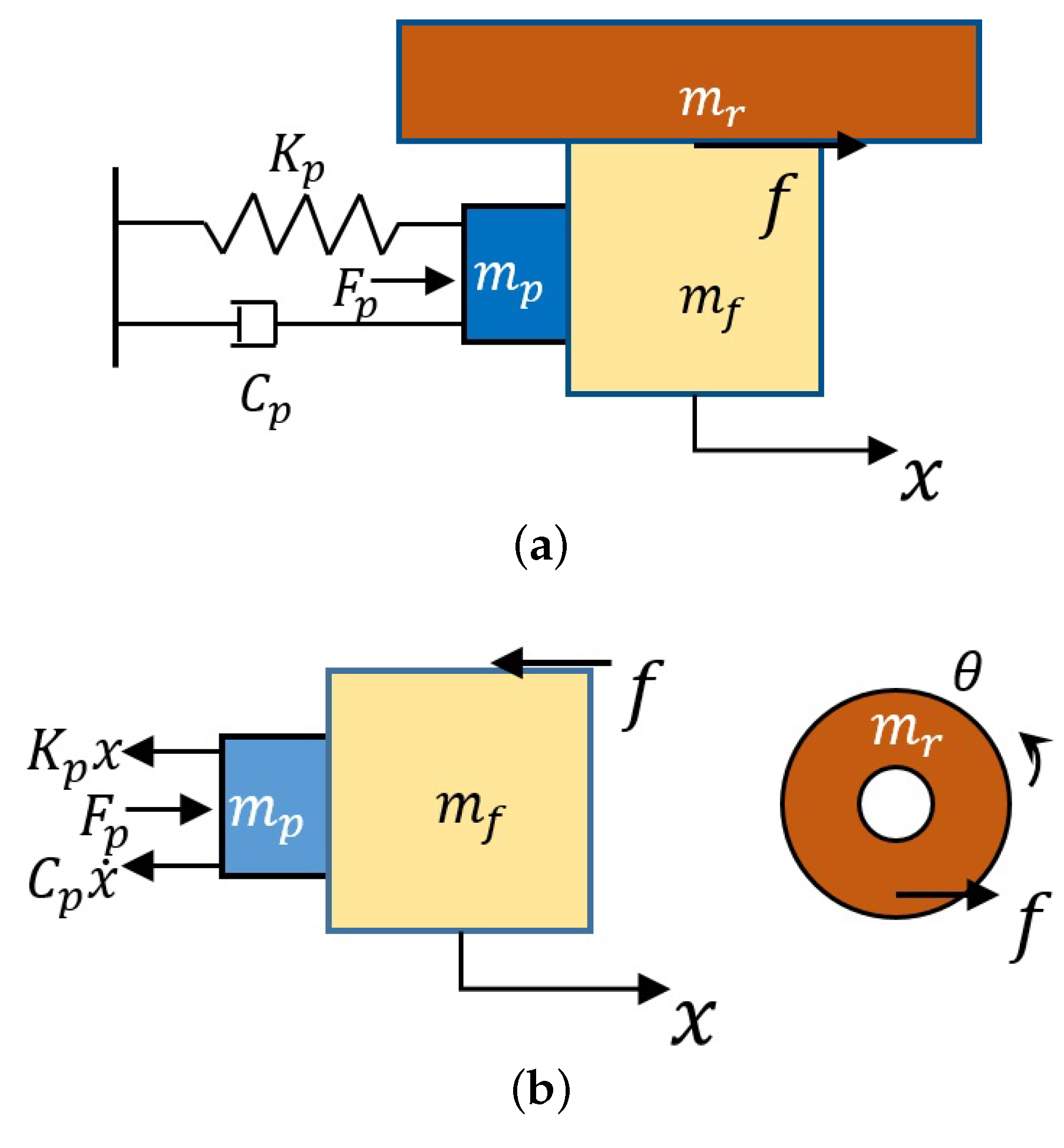
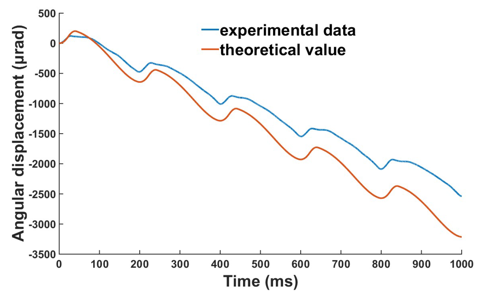
3. Analysis
4. Experiments
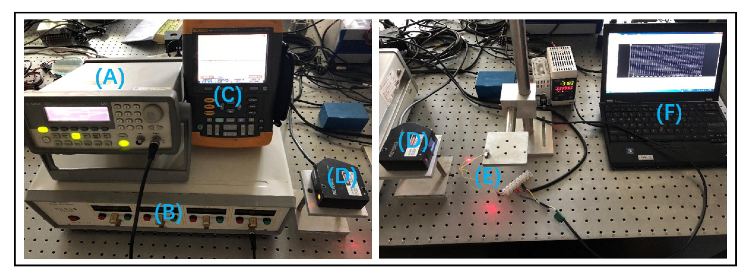
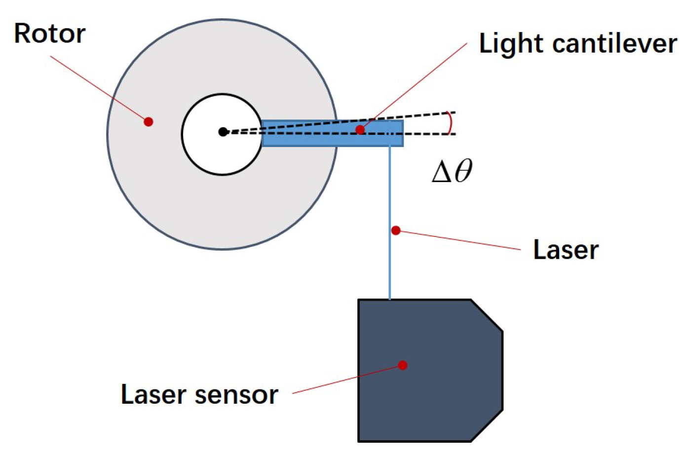
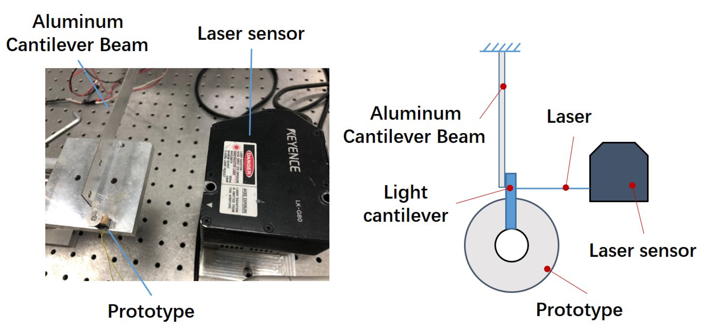
4.1. Experimental System
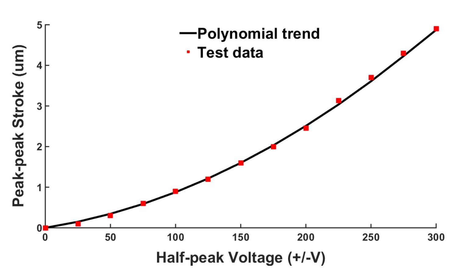
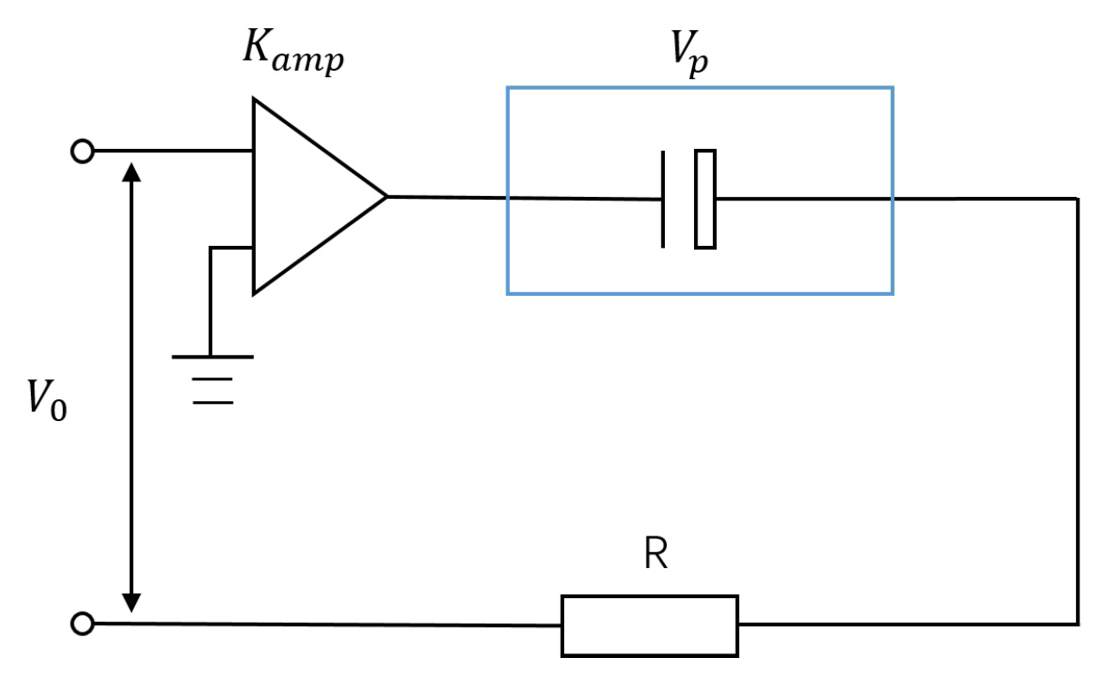
4.2. Characteristics of the Shear Piezo-Stack
4.3. Stepping Rotation Characteristics
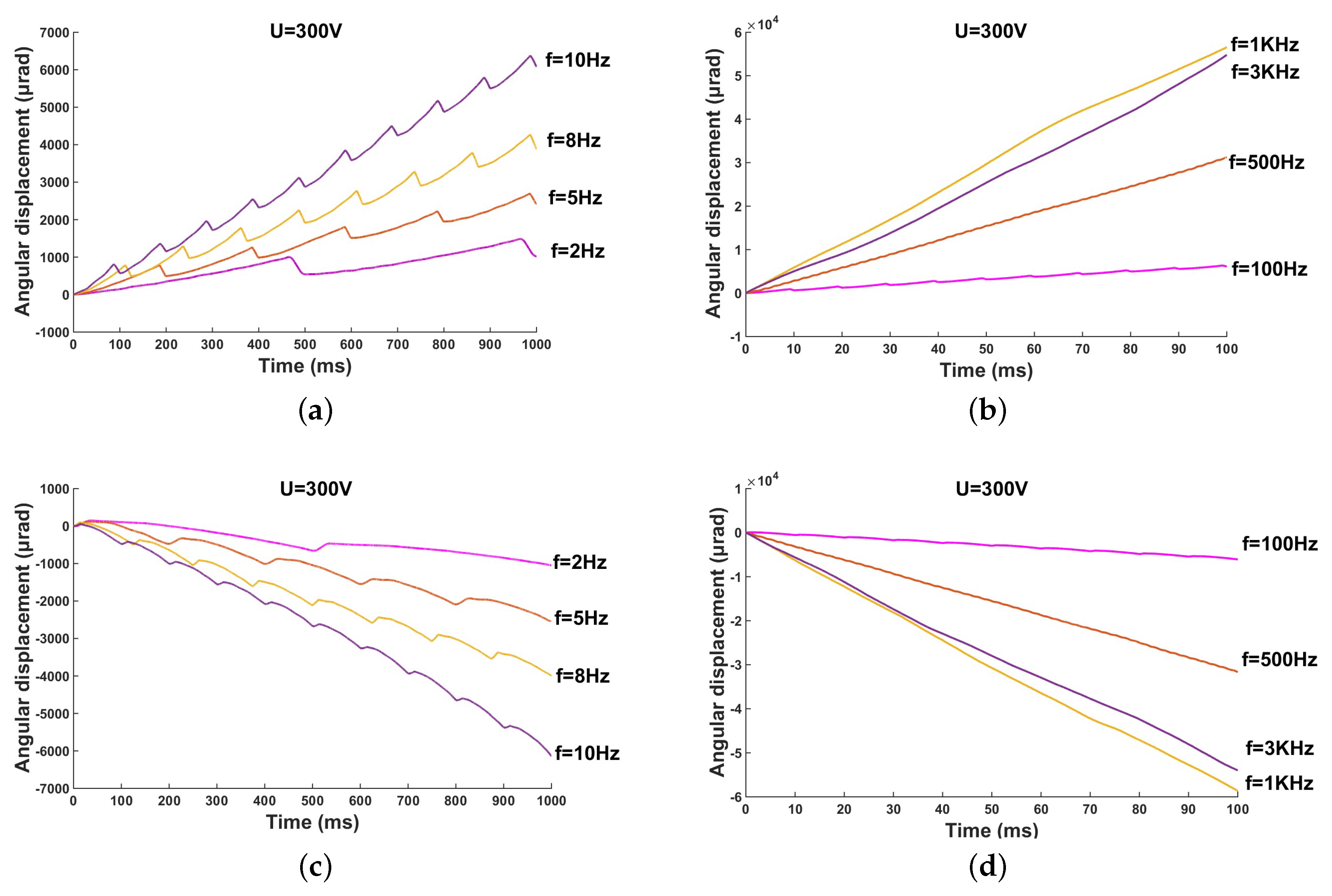
4.3.1. Driving Frequency
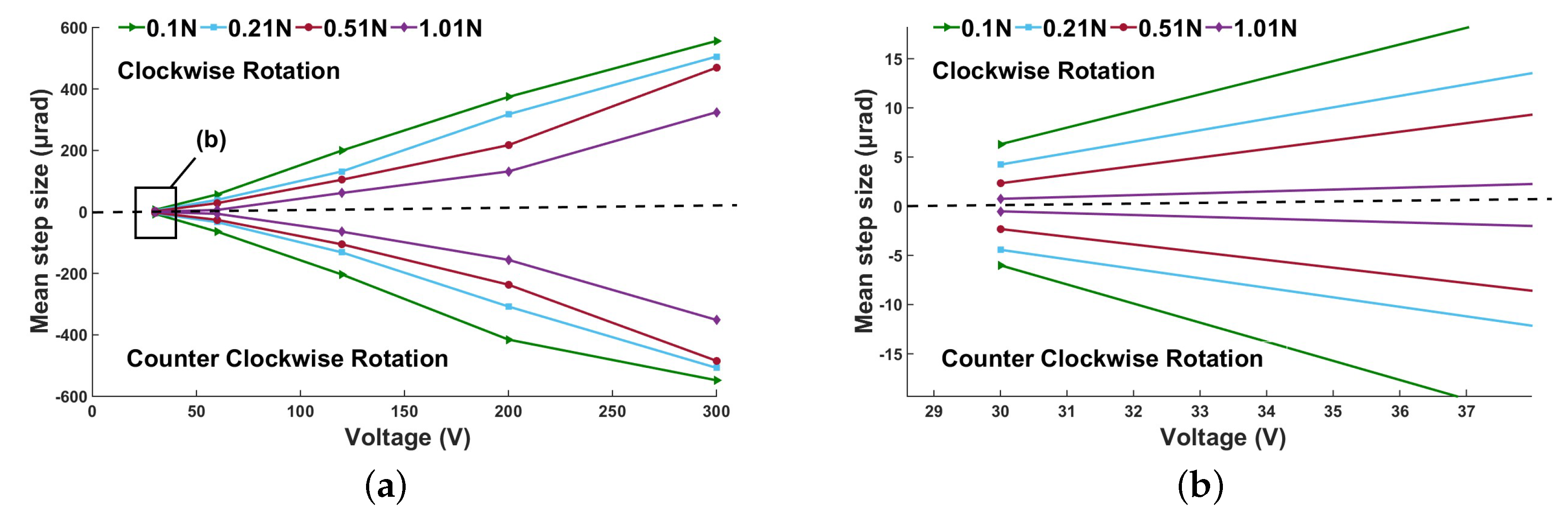
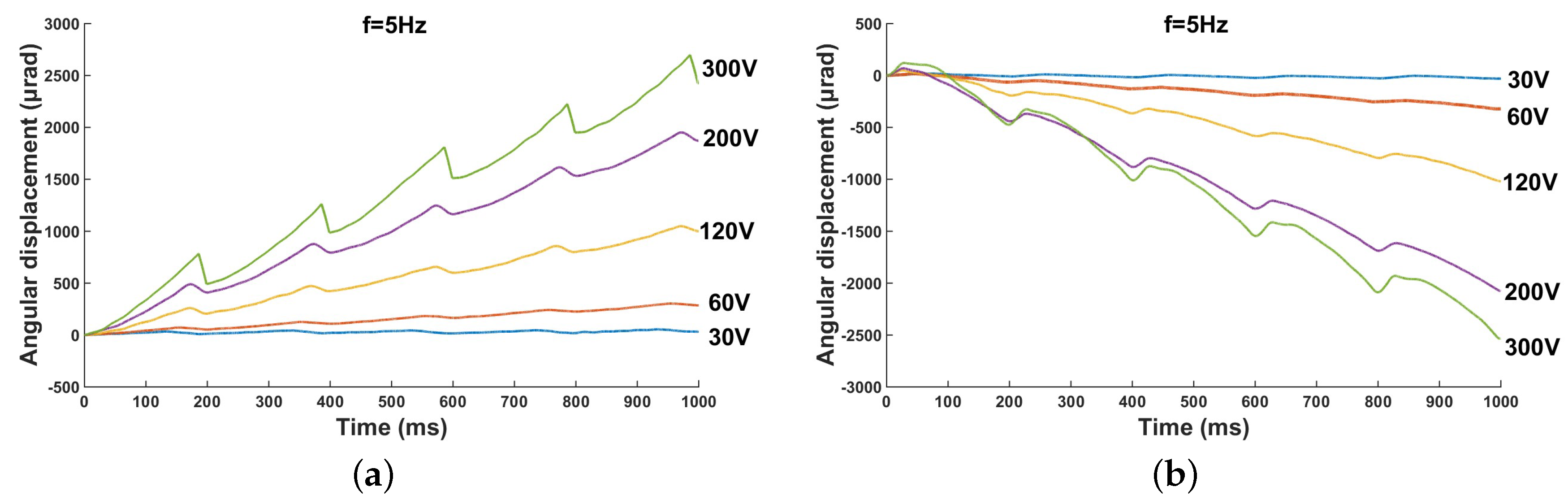
4.3.2. Driving Voltage
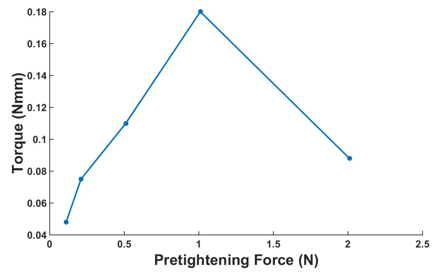
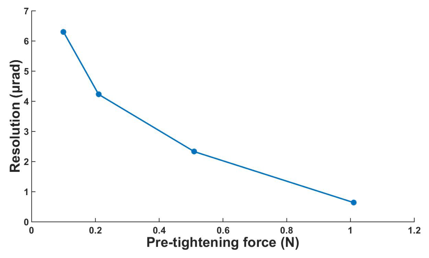
4.3.3. Influence of Preload
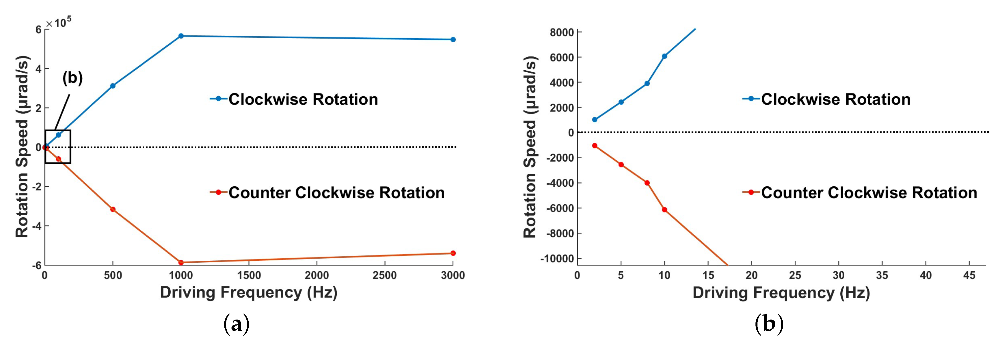
4.3.4. Rotation Speed
4.3.5. Maximum Output Torque
4.4. Comparison of the Rotary Piezoelectric actuators
5. Conclusions
Author Contributions
Funding
Conflicts of Interest
References
- Lu, E.; Li, W.; Yang, X.; Wang, Y.; Liu, Y. Dynamic Modeling and Analysis of a Rotating Piezoelectric Smart Beam. Int. J. Struct. Stab. Dyn. 2017, 18, 19. [Google Scholar] [CrossRef]
- Nezami, M.; Gholami, B. Active Flutter Control of a Supersonic Honeycomb Sandwich Beam Resting on Elastic Foundation with Piezoelectric Sensor/Actuator Pair. Int. J. Struct. Stab. Dyn. 2015, 15, 20–43. [Google Scholar] [CrossRef]
- Wen, C.M.; Cheng, M.Y. Positioning accuracy improvement of a vision-based optical fiber alignment stage powered by a Piezo-Actuator. In Proceedings of the International Workshop on Robotic and Sensors Environments, Ottawa, ON, Canada, 17–18 October 2008; pp. 70–75. [Google Scholar]
- Nah, S.K.; Zhong, Z.W. A microgripper using piezoelectric actuation for micro-object manipulation. Sens. Actuators A Phys. 2007, 133, 218–224. [Google Scholar] [CrossRef]
- Zubir, M.N.M.; Shirinzadeh, B. Development of a high precision flexure-based microgripper. Precis. Eng. 2009, 33, 362–370. [Google Scholar] [CrossRef]
- Tian, Y.; Zhang, D.; Shirinzadeh, B. Dynamic modelling of a flexure-based mechanism for ultra-precision grinding operation. Precis. Eng. 2011, 35, 554–565. [Google Scholar] [CrossRef]
- Park, J.J.; Kwon, K.; Bang, J.; Cho, N.; Han, C.S.; Choi, N.S. Development of a precision indentation and scratching system with a tool force and displacement control module. Rev. Sci. Instrum. 2007, 78, 2. [Google Scholar] [CrossRef] [PubMed]
- Huang, H.; Zhao, H.; Mi, J.; Yang, J. Experimental research on a modular miniaturization nanoindentation device. Rev. Sci. Instrum. 2011, 82, 256. [Google Scholar] [CrossRef]
- Yong, Y.K.; Moheimani, S.O.; Kenton, B.J.; Leang, K.K. Invited review article: High-speed flexure-guided nanopositioning: Mechanical design and control issues. Rev. Sci. Instrum. 2012, 83, 802–843. [Google Scholar] [CrossRef]
- Salapaka, S.M.; Salapaka, M.V. Scanning Probe Microscopy. Control Syst. IEEE 2015, 28, 65–83. [Google Scholar]
- Tian, X.; Quan, Q.; Wang, L.; Su, Q. An Inchworm Type Piezoelectric Actuator Working in Resonant State. IEEE Access 2018, 6, 18975–18983. [Google Scholar] [CrossRef]
- Peng, Y.F.; Lin, C.M. Intelligent motion control of linear ultrasonic motor with H tracking performance. IET Control Theory Appl. 2007, 1, 9–17. [Google Scholar] [CrossRef]
- Choi, S.B.; Han, S.S.; Lee, Y.S. Fine motion control of a moving stage using a piezoactuator associated with a displacement amplifier. Smart Mater. Struct. 2004, 14, 222. [Google Scholar] [CrossRef]
- Yong, Y.K.; Aphale, S.S.; Moheimani, S.O.R. Design, Identification, and Control of a Flexure-Based XY Stage for Fast Nanoscale Positioning; IEEE Press: New York, NY, USA, 2009; pp. 46–54. [Google Scholar]
- Liu, Y.; Wang, Y.; Liu, J.; Xu, D.; Li, K.; Shan, X.; Deng, J. A Four-Feet Walking-Type Rotary Piezoelectric Actuator with Minute Step Motion. Sensors 2018, 18, 1471. [Google Scholar] [CrossRef] [PubMed]
- Kim, J.; Kang, B. Micro-macro linear piezoelectric motor based on self-moving cell. Mechatronics 2009, 19, 1134–1142. [Google Scholar] [CrossRef]
- Jie, D.; Liu, Y.; Chen, W.; Liu, J. Development and experiment evaluation of an inertial piezoelectric actuator using bending-bending hybrid modes. Sens. Actuators A Phys. 2018, 275, 11–18. [Google Scholar]
- Gao, W.; Sato, S.; Arai, Y. A linear-rotary stage for precision positioning. Precis. Eng. 2010, 34, 301–306. [Google Scholar] [CrossRef]
- Lim, K.J.; Lee, J.S.; Park, S.H.; Kang, S.H.; Kim, H.H. Fabrication and characteristics of impact type ultrasonic motor. J. Eur. Ceram. Soc. 2007, 27, 4159–4162. [Google Scholar] [CrossRef]
- Shimizu, Y.; Peng, Y.; Kaneko, J.; Azuma, T.; Ito, S.; Gao, W.; Lu, T.F. Design and construction of the motion mechanism of an XY micro-stage for precision positioning. Sens. Actuators A Phys. 2013, 201, 395–406. [Google Scholar] [CrossRef]
- Fesperman, R.; Ozturk, O.; Hocken, R.; Ruben, S.; Tsao, T.C.; Phipps, J.; Lemmons, T.; Brien, J.; Caskey, G. Multi-scale Alignment and Positioning System—MAPS. Precis. Eng. 2012, 36, 517–537. [Google Scholar] [CrossRef]
- Wang, S.; Zhang, Z.; Ren, L.; Zhao, H.; Liang, Y.; Zhu, B. Design and driving characteristic researches of a novel bionic stepping piezoelectric actuator with large load capacity based on clamping blocks. Microsyst. Technol. 2015, 21, 1757–1765. [Google Scholar] [CrossRef]
- Sun, X.; Chen, W.; Zhang, J.; Zhou, R.; Chen, W. A novel piezo-driven linear-rotary inchworm actuator. Sens. Actuators A Phys. 2015, 224, 78–86. [Google Scholar] [CrossRef]
- Zhou, M.; Fan, Z.; Ma, Z.; Zhao, H.; Guo, Y.; Hong, K.; Li, Y.; Liu, H.; Wu, D. Design and experimental research of a novel stick-slip type piezoelectric actuator. Micromachines 2017, 8, 150. [Google Scholar] [CrossRef]
- Zhao, H.; Fu, L.; Ren, L.; Huang, H.; Fan, Z.; Li, J.; Qu, H. Design and experimental research of a novel inchworm type piezo-driven rotary actuator with the changeable clamping radius. Rev. Sci. Instrum. 2013, 84, 141–158. [Google Scholar] [CrossRef] [PubMed]
- Liu, Y.T.; Higuchi, T.; Fung, R.F. A novel precision positioning table utilizing impact force of spring mounted piezoelectric actuator part I: Experimental design and results. Precis. Eng. 2003, 27, 14–21. [Google Scholar] [CrossRef]
- Sun, M.; Huang, W.; Wang, Y.; Lu, Q.; Su, Z. Research on A Novel Non-resonant Piezoelectric Linear Motor with Lever Amplification Mechanism. Sens. Actuators A Phys. 2017, 261, 302–310. [Google Scholar] [CrossRef]
- Lambert, P.; Valentini, A.; Lagrange, B.; Lit, P.D.; Delchambre, A. Design and performances of a one-degree-of-freedom guided nano-actuator. Robot. Comput. Integr. Manuf. 2003, 19, 89–98. [Google Scholar] [CrossRef]
- Juhas, L.; Vujanic, A.; Adamovic, N.; Nagy, L.; Borovac, B. A platform for micropositioning based on piezo legs. Mechatronics 2001, 11, 869–897. [Google Scholar] [CrossRef]
- Hii, K.F.; Vallance, R.R.; Mengu, M.P. Design, operation, and motion characteristics of a precise piezoelectric linear motor. Precis. Eng. 2010, 34, 231–241. [Google Scholar] [CrossRef]
- Cheng, G.; Hu, Y.; Wen, J.; Zeng, P.; Xing, C. Piezoelectric inertial rotary actuators based on asymmetrically clamping structures. Sens. Actuators A Phys. 2015, 223, 125–133. [Google Scholar] [CrossRef]
- Dewit, C.; Olsson, H.; Astrom, K.; Lischinsky, P. A new model for control of systems with friction. IEEE Trans. Autom. Control 1995, 40, 419–425. [Google Scholar] [Green Version]
- Leemput, L.E.C.V.D.; Rongen, P.H.H.; Timmerman, B.H.; Kempen, H.V. Calibration and characterization of piezoelectric elements as used in scanning tunneling microscopy. Rev. Sci. Instrum. 1991, 62, 989. [Google Scholar] [CrossRef]
- Akila, J.; Wadhwa, S.S. Correction for nonlinear behavior of piezoelectric tube scanners used in scanning tunneling and atomic force microscopy. Rev. Sci. Instrum. 1995, 66, 2517–2519. [Google Scholar] [CrossRef]
- Li, J.; Zhou, X.; Zhao, H.; Shao, M.; Fan, Z.; Liu, H. Design and experimental tests of a dual-servo piezoelectric nanopositioning stage for rotary motion. Rev. Sci. Instrum. 2015, 86, 045002. [Google Scholar] [CrossRef] [PubMed]
- Wang, S.; Rong, W.; Wang, L.; Pei, Z.; Sun, L. Design, analysis and experimental performance of a novel stick-slip type piezoelectric rotary actuator based on variable force couple driving. Smart Mater. Struct. 2017, 26, 055005. [Google Scholar] [CrossRef]


| Authors | Year | Resolution | Maximum Dimension | Drive Voltage | Velocity |
|---|---|---|---|---|---|
| This paper | N/A | 0.64 μrad | 12 mm | 30–300 V | 0.5 rad/s |
| Cheng G et al. [31] | 2015 | 0.85 μrad | Over 90 mm | 20–100 V | 4.02 rad/s |
| Li J et al. [35] | 2015 | 1.54 μrad | Over 20 mm | 35–100 V | 0.032 rad/s |
| Wang S et al. [36] | 2017 | 0.75 μrad | 140 mm | 9 V–120 V | N/A |
| Yingxiang L et al. [15] | 2018 | 0.095 μrad | Over 160 mm | 25–210 V | N/A |
© 2019 by the authors. Licensee MDPI, Basel, Switzerland. This article is an open access article distributed under the terms and conditions of the Creative Commons Attribution (CC BY) license (http://creativecommons.org/licenses/by/4.0/).
Share and Cite
Huang, H.; Wang, L.; Wu, Y. Design and Experimental Research of a Rotary Micro-Actuator Based on a Shearing Piezoelectric Stack. Micromachines 2019, 10, 96. https://doi.org/10.3390/mi10020096
Huang H, Wang L, Wu Y. Design and Experimental Research of a Rotary Micro-Actuator Based on a Shearing Piezoelectric Stack. Micromachines. 2019; 10(2):96. https://doi.org/10.3390/mi10020096
Chicago/Turabian StyleHuang, Hehe, Longfei Wang, and Ying Wu. 2019. "Design and Experimental Research of a Rotary Micro-Actuator Based on a Shearing Piezoelectric Stack" Micromachines 10, no. 2: 96. https://doi.org/10.3390/mi10020096
APA StyleHuang, H., Wang, L., & Wu, Y. (2019). Design and Experimental Research of a Rotary Micro-Actuator Based on a Shearing Piezoelectric Stack. Micromachines, 10(2), 96. https://doi.org/10.3390/mi10020096