Plasma Surface Functionalization of Carbon Nanofibres with Silver, Palladium and Platinum Nanoparticles for Cost-Effective and High-Performance Supercapacitors


Abstract
1. Introduction
2. Materials and Methods
2.1. Sample Preparation
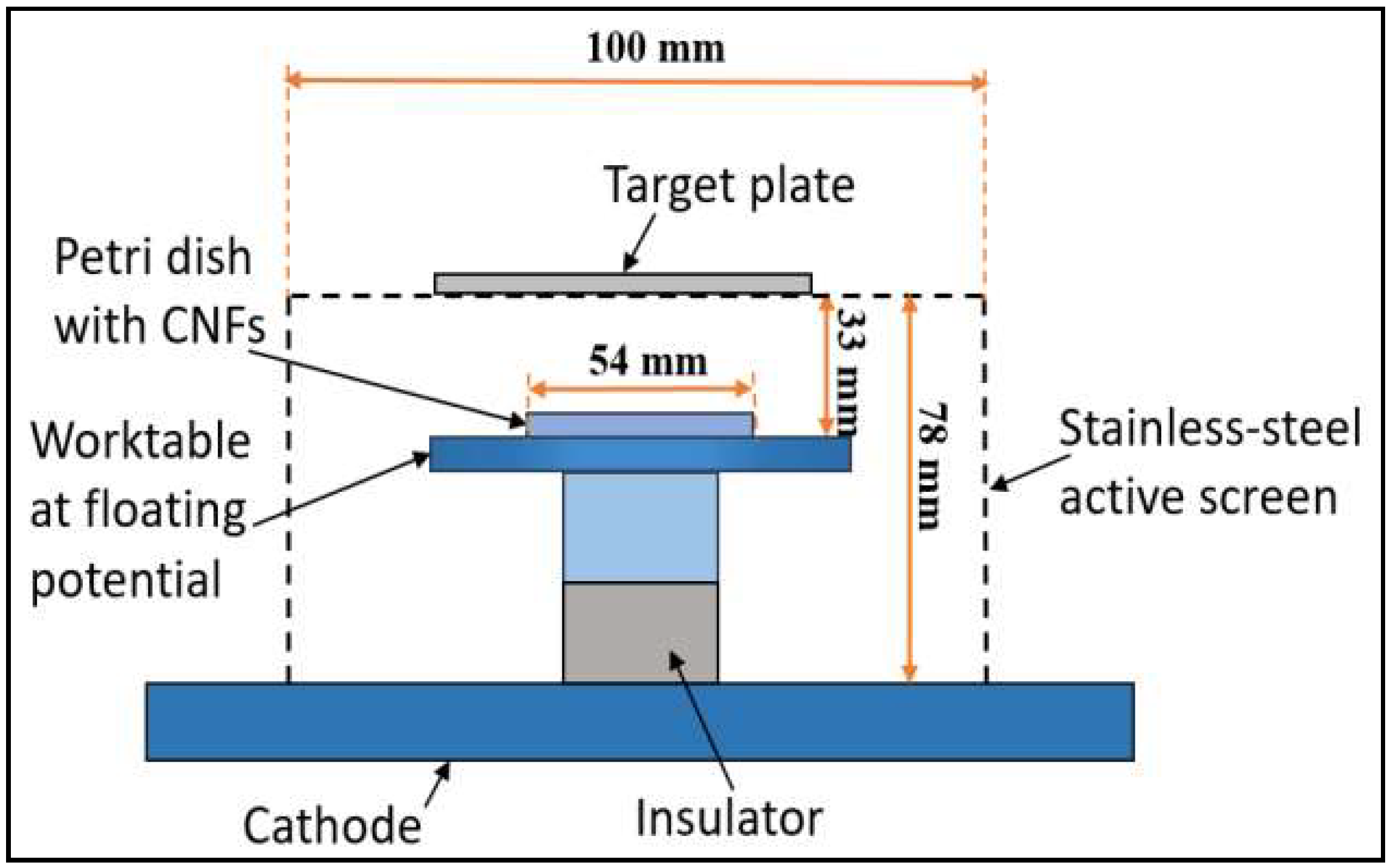
2.2. Active-Screen Plasma Sputtering (ASPS)
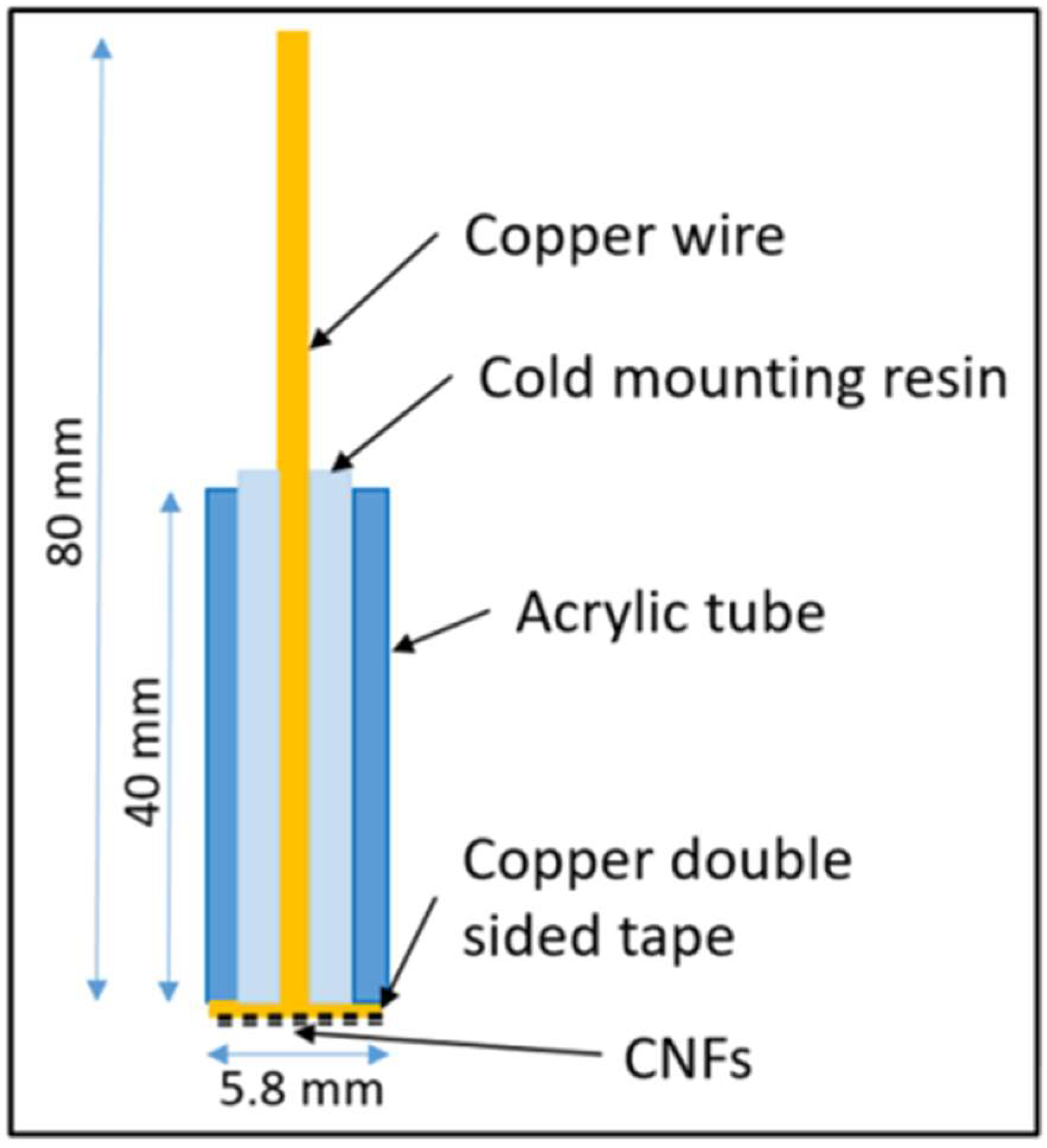
2.3. Fabrication of Electrodes
2.4. Microstructure Characterisation
2.5. Electrochemical Test
3. Results
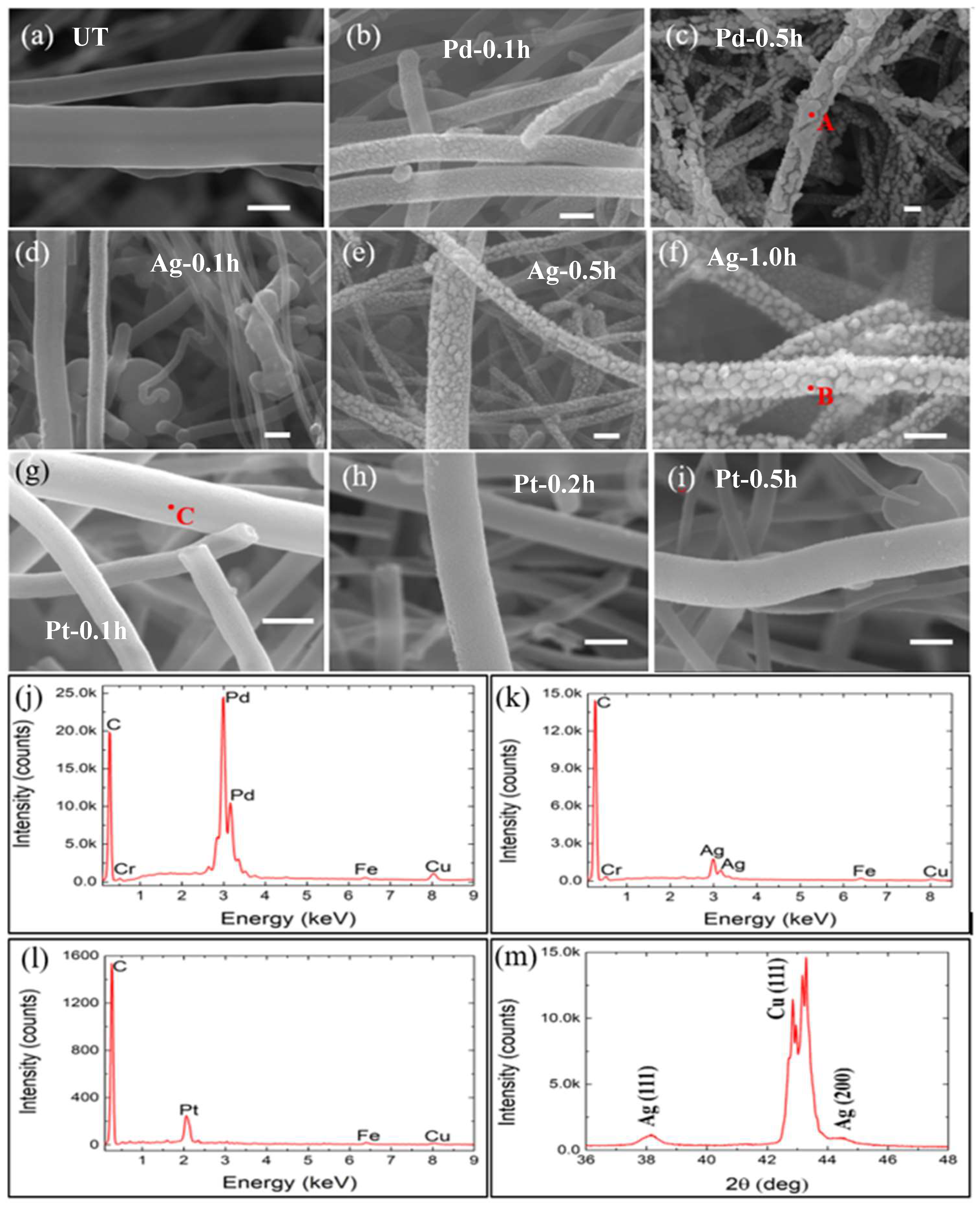
3.1. Microstructure
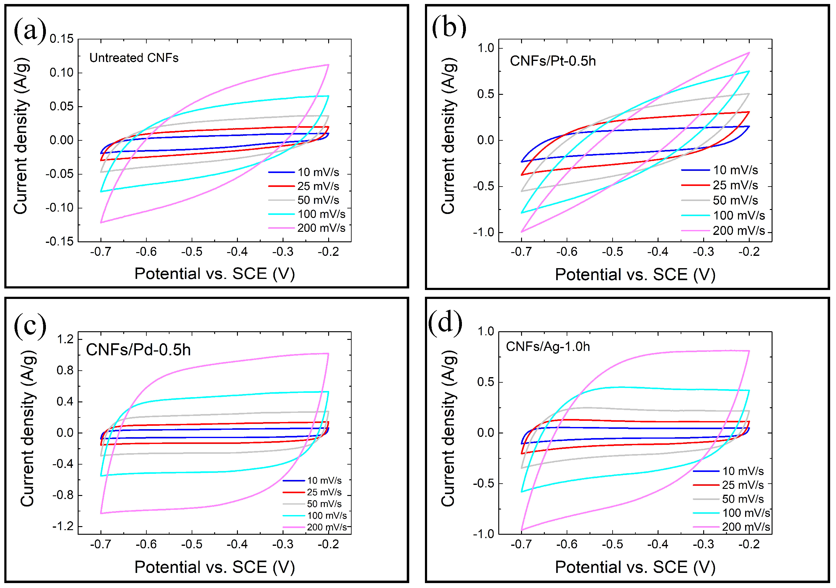
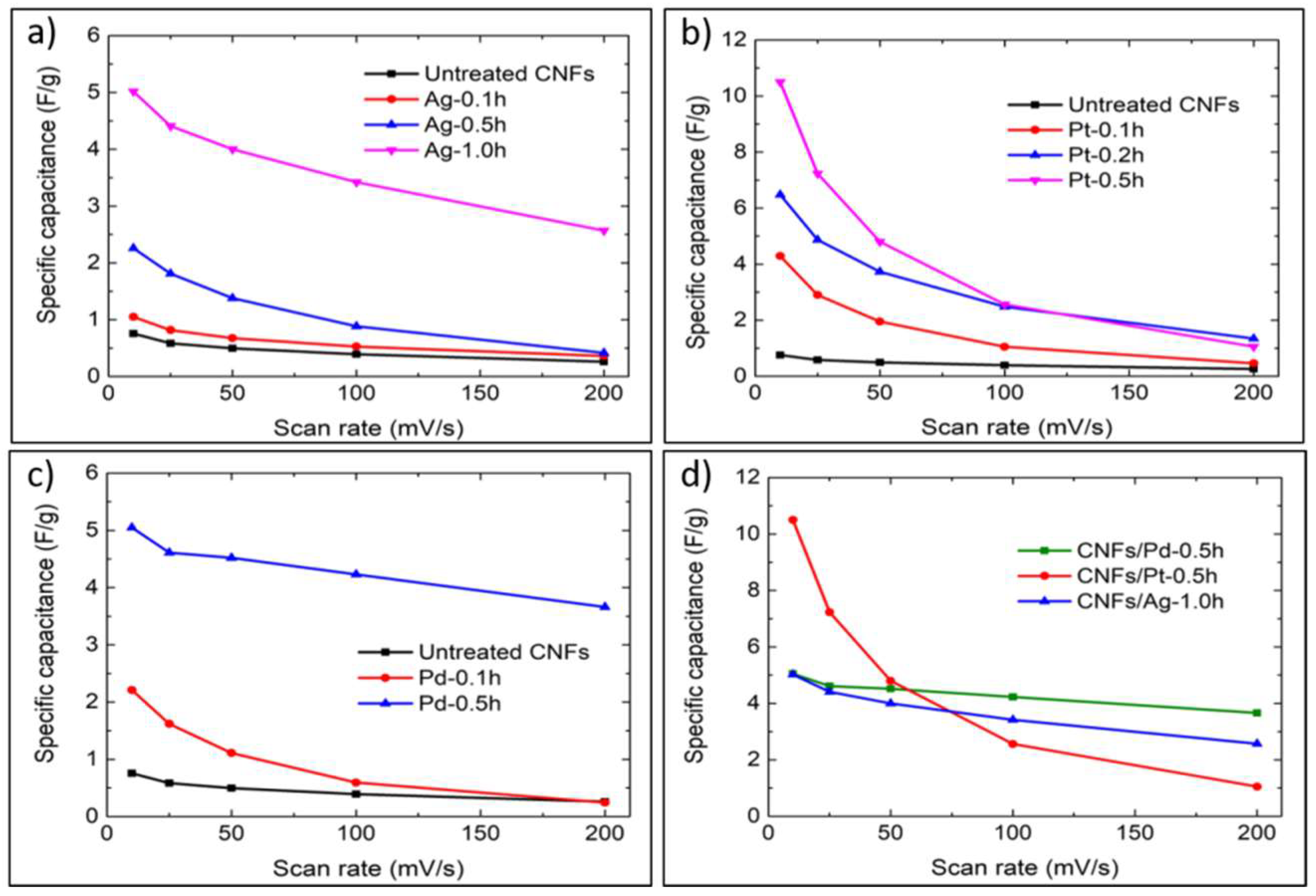
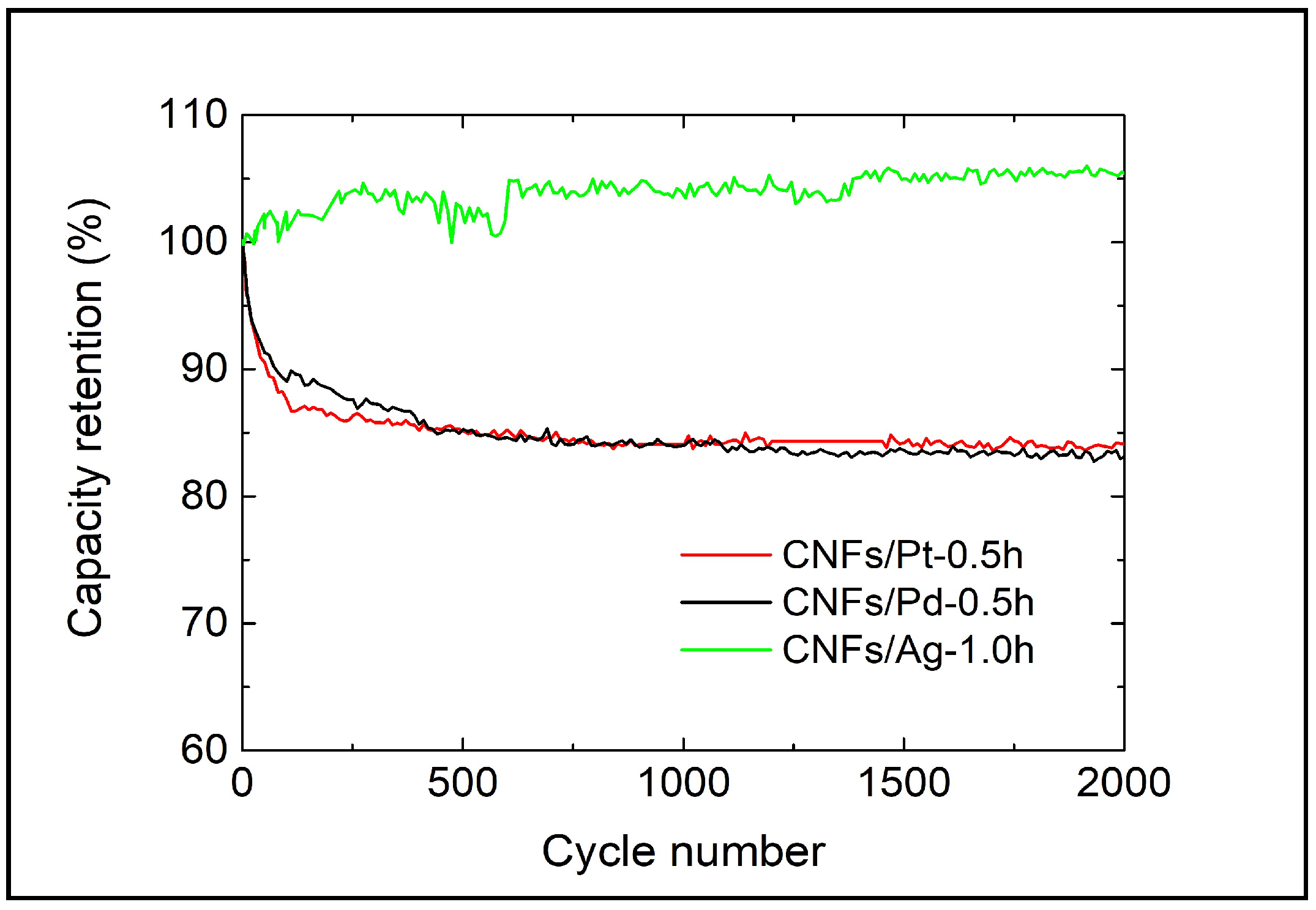
3.2. Electrochemical Performance
4. Discussion
4.1. Effect of the Nanoparticle Deposition on the Electrochemical Performance of CNFs
4.2. Potential Application of the Functionalised CNFs
5. Conclusions
Author Contributions
Funding
Acknowledgments
Conflicts of Interest
References
- Wang, G.; Zhang, L.; Zhang, J. A review of electrode materials for electrochemical supercapacitors. Chem. Soc. Rev. 2012, 41, 797–828. [Google Scholar] [CrossRef]
- Wang, H.; Xu, Z.; Yi, H.; Wei, H.; Guo, Z.; Wang, X. One-step preparation of single-crystalline Fe2O3 particles/graphene composite hydrogels as high performance anode materials for supercapacitors. Nano Energy 2014, 7, 86. [Google Scholar] [CrossRef]
- Erwin, W.R.; Zarick, H.F.; Talbert, E.M.; Bardhan, R. Light trapping in mesoporous solar cells with plasmonic nanostructures. Energy Environ. Sci. 2016, 9, 1577. [Google Scholar] [CrossRef]
- Malgras, V.; Ji, Q.; Kamachi, Y.; Mori, T.; Shieh, F.-K.; Wu, K.C.-W.; Ariga, K.; Yamauchi, Y. Templated synthesis for nanoarchitectured porous materials. Bull. Chem. Soc. Jpn. 2015, 88, 1171. [Google Scholar] [CrossRef]
- Liu, H.; Huang, Z.; Wei, S.; Zheng, L.; Xiao, L.; Gong, Q. Nano-structured electron transporting materials for perovskite solar cells. Nanoscale 2016, 8, 6209. [Google Scholar] [CrossRef] [PubMed]
- Bairi, P.; Minami, K.; Hill, J.P.; Nakanishi, W.; Shrestha, L.K.; Liu, C.; Harano, K.; Nakamura, E.; Ariga, K. Supramolecular differentiation for construction of anisotropic fullerene nanostructures by time-programmed control of interfacial growth. ACS Nano 2016, 10, 8796. [Google Scholar] [CrossRef] [PubMed]
- Sakaushi, K.; Antonietti, M. Carbon- and nitrogen-based porous solids: A recently emerging class of materials. Bull. Chem. Soc. Jpn. 2015, 88, 386. [Google Scholar] [CrossRef]
- Huang, Z.; Che, S. Fabrication of mesostructured silica materials through Co-structure-directing route. Bull. Chem. Soc. Jpn. 2015, 88, 617. [Google Scholar] [CrossRef]
- Yamamoto, E.; Kuroda, K. Colloidal mesoporous silica nanoparticles. Bull. Chem. Soc. Jpn. 2016, 89, 501. [Google Scholar] [CrossRef]
- Tabuchi, H.; Urita, K.; Moriguchi, I. Effect of carbon nanospace on charge–discharge properties of Si and SiOx nanoparticles-embedded nanoporous carbons. Bull. Chem. Soc. Jpn. 2015, 88, 1378. [Google Scholar] [CrossRef]
- Wu, K.; Lian, T. Quantum confined colloidal nanorod heterostructures for solar-to-fuel conversion. Chem. Soc. Rev. 2016, 45, 3781. [Google Scholar] [CrossRef] [PubMed]
- Lewis, N.S. Research opportunities to advance solar energy utilization. Science 2016, 351, aad1920. [Google Scholar] [CrossRef] [PubMed]
- Xiao, Z.; Lei, H.; Zhang, X.; Zhou, Y.; Hosono, H.; Kamiya, T. Ligand-hole in [SnI6] unit and origin of band gap in photovoltaic perovskite variant Cs2SnI6. Bull. Chem. Soc. Jpn. 2015, 88, 1250. [Google Scholar] [CrossRef]
- Shibayama, N.; Ozawa, H.; Ooyama, Y.; Arakawa, H. Highly efficient cosensitized plastic-substrate dye-sensitized solar cells with black dye and pyridine-anchor organic dye. Bull. Chem. Soc. Jpn. 2015, 88, 366. [Google Scholar] [CrossRef]
- Feng, D.; Lv, Y.; Wu, Z.; Dou, Y.; Han, L.; Sun, Z.; Xia, Y.; Zheng, G.; Zhao, D. Free-standing mesoporous carbon thin films with highly ordered pore architectures for nanodevices. J. Am. Chem. Soc. 2011, 133, 15148–15156. [Google Scholar] [CrossRef] [PubMed]
- Zhang, L.L.; Zhao, X.S. Carbon-based materials as supercapacitor electrodes. Chem. Soc. Rev. 2009, 38, 2520–2531. [Google Scholar] [CrossRef] [PubMed]
- Xiao, K.; Ding, L.X.; Liu, G.; Chen, H.; Wang, S.; Wang, H. Freestanding, hydrophilic nitrogen-doped carbon foams for highly compressible all solid-state supercapacitors. Adv. Mater. 2016, 28, 5997–6002. [Google Scholar] [CrossRef]
- Pushparaj, V.L.; Shaijumon, M.M.; Kumar, A.; Murugesan, S.; Ci, L.; Vajtai, R.; Linhardt, R.J.; Nalamasu, O.; Ajayan, P.M. Flexible energy storage devices based on nanocomposite paper. Proc. Natl. Acad. Sci. USA 2007, 104, 13574–13577. [Google Scholar] [CrossRef] [PubMed]
- Zhu, Y.; Murali, S.; Stoller, M.D.; Ganesh, K.J.; Cai, W.; Ferreira, P.J.; Pirkle, A.; Wallace, R.M.; Cychosz, K.A.; Thommes, M.; et al. Carbon-based supercapacitors produced by activation of graphene. Science 2011, 332, 1537. [Google Scholar] [CrossRef] [PubMed]
- Peng, X.; Peng, L.; Wu, C.; Xie, Y. Two dimensional nanomaterials for flexible supercapacitors. Chem. Soc. Rev. 2014, 43, 3303. [Google Scholar] [CrossRef]
- Peng, L.; Zhu, Y.; Li, H.; Yu, G. Chemically integrated inorganic-graphene two-dimensional hybrid materials for flexible energy storage devices. Small 2016, 12, 6183. [Google Scholar] [CrossRef] [PubMed]
- Peng, L.; Zhu, Y.; Chen, D.; Ruoff, R.S.; Yu, G. Two-dimensional materials for beyond-lithium-ion batteries. Adv. Energy Mater. 2016, 6, 1600025. [Google Scholar] [CrossRef]
- Khan, A.H.; Ghosh, S.; Pradhan, B.; Dalui, A.; Shrestha, L.K.; Acharya, S.; Ariga, K. Bull. Two-dimensional (2D) nanomaterials towards electrochemical nanoarchitectonics in energy-related applications. Bull. Chem. Soc. Jpn. 2017, 90, 627–648. [Google Scholar] [CrossRef]
- Sengottaiyan, C.; Jayavel, R.; Bairi, P. Cobalt oxide/reduced graphene oxide composite with enhanced electrochemical supercapacitance performance. Bull. Chem. Soc. Jpn. 2017, 90, 955–962. [Google Scholar] [CrossRef]
- Dubal, D.P.; Chodankar, N.R.; Kim, D.-H.; Gomez-Romero, P. Towards flexible solid-state supercapacitors for smart and wearable electronics. Chem. Soc. Rev. 2018, 47, 2065–2129. [Google Scholar] [CrossRef] [PubMed]
- Yang, C.; Zhou, M.; Xu, Q. Three-dimensional ordered macroporous MnO2/carbon nanocomposites as high-performance electrodes for asymmetric supercapacitors. Phys. Chem. Chem. Phys. 2013, 15, 19730–19740. [Google Scholar] [CrossRef]
- Zhong, C.; Deng, Y.; Hu, W.; Qiao, J.; Zhang, L.; Zhang, J. A review of electrolyte materials and compositions for electrochemical supercapacitors. Chem. Soc. Rev. 2015, 44, 7484–7539. [Google Scholar] [CrossRef]
- Yang, L.; Cheng, S.; Ding, Y.; Zhu, X.; Wang, Z.L.; Liu, M. Hierarchical network architectures of carbon fiber paper supported cobalt oxide nanonet for high-capacity pseudocapacitors. Nano Lett. 2012, 12, 321–325. [Google Scholar] [CrossRef]
- Frackowiak, E.; Béguin, F. Carbon materials for the electrochemical storage of energy in capacitors. Carbon 2001, 39, 937–950. [Google Scholar] [CrossRef]
- Fan, Z.; Yan, J.; Wei, T.; Zhi, L.; Ning, G.; Li, T.; Wei, F. Asymmetric supercapacitors based on graphene/MnO2 and activated carbon nanofiber electrodes with high power and energy density. Adv. Funct. Mater. 2011, 21, 2366–2375. [Google Scholar] [CrossRef]
- Wang, D.-W.; Li, F.; Liu, M.; Lu, G.Q.; Cheng, H.-M. 3D aperiodic hierarchical porous graphitic carbon material for high-rate electrochemical capacitive energy storage. Angew. Chem. 2008, 120, 379–382. [Google Scholar] [CrossRef]
- Zhai, Y.; Dou, Y.; Zhao, D.; Fulvio, P.F.; Mayes, R.T.; Dai, S. Carbon materials for chemical capacitive energy storage. Adv. Mater. 2011, 23, 4828–4850. [Google Scholar] [CrossRef] [PubMed]
- Raymundo-Piñero, E.; Leroux, F.; Béguin, F. A high-performance carbon for supercapacitors obtained by carbonization of a seaweed biopolymer. Adv. Mater. 2006, 18, 1877–1882. [Google Scholar] [CrossRef]
- Kim, C.; Ngoc, B.T.N.; Yang, K.S.; Kojima, M.; Kim, Y.A.; Kim, Y.J.; Endo, M.; Yang, S.C. Self-sustained thin webs consisting of porous carbon nanofibers for supercapacitors via the electrospinning of polyacrylonitrile solutions containing zinc chloride. Adv. Mater. 2007, 19, 2341–2346. [Google Scholar] [CrossRef]
- Kim, C.; Yang, K.S.; Kojima, M.; Yoshida, K.; Kim, Y.J.; Kim, Y.A.; Endo, M. Fabrication of electrospinning-derived carbon nanofiber webs for the anode material of lithium-ion secondary batteries. Adv. Funct. Mater. 2006, 16, 2393–2397. [Google Scholar] [CrossRef]
- Wang, G.; Pan, C.; Wang, L.; Dong, Q.; Yu, C.; Zhao, Z.; Qiu, J. Activated carbon nanofiber webs made by electrospinning for capacitive deionization. Electrochim. Acta 2012, 69, 65–70. [Google Scholar] [CrossRef]
- Al-Saleh, M.H.; Sundararaj, U. A review of vapor grown carbon nanofiber/polymer conductive composites. Carbon 2009, 47, 2–22. [Google Scholar] [CrossRef]
- Tibbetts, G.; Lake, M.; Strong, K.; Rice, B. A review of the fabrication and properties of vapor-grown carbon nanofiber/polymer composites. Compos. Sci. Technol. 2007, 67, 1709–1718. [Google Scholar] [CrossRef]
- Janas, D.; Koziol, K.K.K. The influence of metal nanoparticles on electrical properties of carbon nanotubes. Appl. Surf. Sci. 2016, 376, 74–78. [Google Scholar] [CrossRef]
- Li, C.; Bell, T.; Dong, H. A study of active screen plasma nitriding. Surf. Eng. 2013, 18, 174–181. [Google Scholar] [CrossRef]
- Soin, N.; Roy, S.S.; Karlsson, L.; McLaughlin, J.A. Sputter deposition of highly dispersed platinum nanoparticles on carbon nanotube arrays for fuel cell electrode material. Diam. Relat. Mater. 2010, 19, 595–598. [Google Scholar] [CrossRef]
- Zacharia, R.; Rather, S.-U.; Hwang, S.W.; Nahm, K.S. Spillover of physisorbed hydrogen from sputter-deposited arrays of platinum nanoparticles to multi-walled carbon nanotubes. Chem. Phys. Lett. 2007, 434, 286–291. [Google Scholar] [CrossRef]
- He, Z.; Chen, J.; Liu, D.; Zhou, H.; Kuang, Y. Electrodeposition of Pt–Ru nanoparticles on carbon nanotubes and their electrocatalytic properties for methanol electrooxidation. Diam. Relat. Mater. 2004, 13, 1764–1770. [Google Scholar] [CrossRef]
- Lin, Z.; Ji, L.; Zhang, X. Electrodeposition of platinum nanoparticles onto carbon nanofibers for electrocatalytic oxidation of methanol. Mater. Lett. 2009, 63, 2115–2118. [Google Scholar] [CrossRef]
- Chen, X.; Xia, J.; Peng, J.; Li, W.; Xie, S. Carbon-nanotube metal-matrix composites prepared by electroless plating. Compos. Sci. Technol. 2000, 60, 301–306. [Google Scholar] [CrossRef]
- Faraji, S.; Ani, F.N. The development supercapacitor from activated carbon by electroless plating—A review. Renew. Sustain. Energy Rev. 2015, 42, 823–834. [Google Scholar] [CrossRef]
- Arulepp, M.; Permann, L.; Leis, J.; Perkson, A.; Rumma, K.; Jänes, A.; Lust, E. Influence of the solvent properties on the characteristics of a double layer capacitor. J. Power Sources 2004, 133, 320–328. [Google Scholar] [CrossRef]
- Allagui, A.; Freeborn, T.J.; Elwakil, A.S.; Maundy, B.J. Reevaluation of performance of electric double-layer capacitors from constant-current charge/discharge and cyclic voltammetry. Sci. Rep. 2016, 6, 38568. [Google Scholar] [CrossRef]
- Corujeira-Gallo, S.; Dong, H. On the fundamental mechanisms of acitve screen plasma nitriding. Vacuum 2010, 84, 321–325. [Google Scholar] [CrossRef]
- Numao, S.; Judai, K.; Nishijo, J.; Mizuuchi, K.; Nishi, N. Synthesis and characterization of mesoporous carbon nano-dendrites with graphitic ultra-thin walls and their application to supercapacitor electrodes. Carbon 2009, 47, 306–312. [Google Scholar] [CrossRef]
- Hsia, B.; Marschewski, J.; Wang, S.; In, J.B.; Carraro, C.; Poulikakos, D.; Grigoropoulos, C.P.; Maboudian, R. Highly flexible, all solid-state micro-supercapacitors from vertically aligned carbon nanotubes. Nanotechnology 2014, 25, 055401. [Google Scholar] [CrossRef] [PubMed]
- Bao, L.; Zang, J.; Li, X. Flexible Zn2SnO4/MnO2 core/shell nanocable-carbon microfiber hybrid composites for high-performance supercapacitor electrodes. Nano Lett. 2011, 11, 1215–1220. [Google Scholar] [CrossRef] [PubMed]
- Yan, J.; Wei, T.; Shao, B.; Ma, F.; Fan, Z.; Zhang, M.; Zheng, C.; Shang, Y.; Qian, W.; Wei, F. Electrochemical properties of graphene nanosheet/carbon black composites as electrodes for supercapacitors. Carbon 2010, 48, 1731–1737. [Google Scholar] [CrossRef]
- Testing Electrochemical Capacitors: Cyclic Charge-Discharge-Stacks. Available online: https://www.gamry.com/application-notes/battery-research/electrochemical-capacitors-cyclic-charge-discharge-and-stacks (accessed on 9 June 2018).
- Gamby, J.; Taberna, P.L.; Simon, P.; Fauvarque, J.F.; Chesneau, M. Studies and characterisations of various activated carbons used for carbon/carbon supercapacitors. J. Power Sources 2001, 101, 109–116. [Google Scholar] [CrossRef]
- Gui, Z.; Zhu, H.; Gillette, E.; Han, X.; Rubloff, G.W.; Hu, L.; Lee, S.B. Natural cellulose fiber as substrate for supercapacitor. ACS Nano 2013, 7, 6037–6046. [Google Scholar] [CrossRef] [PubMed]
- Cai, J.; Niu, H.; Wang, H.; Shao, H.; Fang, J.; He, J.; Xiong, H.; Ma, C.; Lin, T. High-performance supercapacitor electrode from cellulose-derived, inter-bonded carbon nanofibers. J. Power Sources 2016, 324, 302–308. [Google Scholar] [CrossRef]
- Liu, C.; Yu, Z.; Neff, D.; Zhamu, A.; Jang, B.Z. Graphene-based supercapacitor with an ultrahigh energy density. Nano Lett. 2010, 10, 4863–4868. [Google Scholar] [CrossRef] [PubMed]
- Liu, C.; Li, F.; Ma, L.P.; Cheng, H.M. Advanced materials for energy storage. Adv. Mater. 2010, 22, E28–E62. [Google Scholar] [CrossRef]
- Largeot, C.; Portet, C.; Chmiola, J.; Taberna, P.-L.; Gogotsi, Y.; Simon, P. Relation between the ion size and pore size for an electric double-layer capacitor. JACS 2008, 130, 2730–2731. [Google Scholar] [CrossRef]
- Volkov, A.G.; Paula, S.; Deamer, D.W. Two mechanisms of permeation of small neutral molecules and hydrated ions across phospholipid bilayers. Bioelectrochem. Bioenerg. 1997, 42, 153–160. [Google Scholar] [CrossRef]
- Nightingale, E.R. Phenomenological theory of ion solvation. Effective radii of hydrated ions. J. Phys. Chem. 1959, 63, 1381–1387. [Google Scholar] [CrossRef]
- Yuan, L.; Xiao, X.; Ding, T.; Zhong, J.; Zhang, X.; Shen, Y.; Hu, B.; Huang, Y.; Zhou, J.; Wang, Z.L. Paper-based supercapacitors for self-powered nanosystems. Angew. Chem. Int. Ed. Engl. 2012, 51, 4934–4938. [Google Scholar] [CrossRef] [PubMed]
- Zhi, M.; Xiang, C.; Li, J.; Li, M.; Wu, N. Nanostructured carbon-metal oxide composite electrodes for supercapacitors: A review. Nanoscale 2013, 5, 72–88. [Google Scholar] [CrossRef]
- Yamada, H.; Nakamura, H.; Nakahara, F.; Moriguchi, I.; Kudo, T. Electrochemical study of high electrochemical double layer capacitance of ordered porous carbons with both meso/macropores and micropores. J. Phys. Chem. C 2007, 111, 227–233. [Google Scholar] [CrossRef]


| Sample Code | Target Material | Gas | Pressure (mbar) | Temperature (°C) | Time (h) |
|---|---|---|---|---|---|
| CNFs/Ag-0.1h | Silver | 25% Ar + 75% H2 | 0.75 | 320 | 0.1 |
| CNFs/Ag-0.5h | Silver | 0.5 | |||
| CNFs/Ag-1.0h | Silver | 1.0 | |||
| CNFs/Pt-0.1h | Platinum | 0.1 | |||
| CNFs/Pt-0.2h | Platinum | 0.2 | |||
| CNFs/Pt-0.5h | Platinum | 0.5 | |||
| CNFs/Pd-0.1h | Palladium | 0.1 | |||
| CNFs/Pd-0.5h | Palladium | 0.5 |
© 2018 by the authors. Licensee MDPI, Basel, Switzerland. This article is an open access article distributed under the terms and conditions of the Creative Commons Attribution (CC BY) license (http://creativecommons.org/licenses/by/4.0/).
Share and Cite
Li, Z.; Qi, S.; Liang, Y.; Zhang, Z.; Li, X.; Dong, H. Plasma Surface Functionalization of Carbon Nanofibres with Silver, Palladium and Platinum Nanoparticles for Cost-Effective and High-Performance Supercapacitors. Micromachines 2019, 10, 2. https://doi.org/10.3390/mi10010002
Li Z, Qi S, Liang Y, Zhang Z, Li X, Dong H. Plasma Surface Functionalization of Carbon Nanofibres with Silver, Palladium and Platinum Nanoparticles for Cost-Effective and High-Performance Supercapacitors. Micromachines. 2019; 10(1):2. https://doi.org/10.3390/mi10010002
Chicago/Turabian StyleLi, Zelun, Shaojun Qi, Yana Liang, Zhenxue Zhang, Xiaoying Li, and Hanshan Dong. 2019. "Plasma Surface Functionalization of Carbon Nanofibres with Silver, Palladium and Platinum Nanoparticles for Cost-Effective and High-Performance Supercapacitors" Micromachines 10, no. 1: 2. https://doi.org/10.3390/mi10010002
APA StyleLi, Z., Qi, S., Liang, Y., Zhang, Z., Li, X., & Dong, H. (2019). Plasma Surface Functionalization of Carbon Nanofibres with Silver, Palladium and Platinum Nanoparticles for Cost-Effective and High-Performance Supercapacitors. Micromachines, 10(1), 2. https://doi.org/10.3390/mi10010002