1. Introduction and Objectives
Observing the plant functional status from space represents a major interest for farming, forest management, and assessment of the terrestrial carbon budget. The measurement of solar induced chlorophyll fluorescence [
1] directly addresses the photosynthetic efficiency of the terrestrial vegetation layer and complements traditional reflectance measurements used to infer parameters like Leaf Area Index (LAI) or chlorophyll absorption [
2]. Fluorescence estimates provide an early and more direct approach for diagnosis of the functioning and health status of vegetation. In fact the fluorescence emission is in competition with the photochemical conversion and may allow more accurate carbon assimilation estimation and earlier stress detection than is possible from only reflectance data [
3].
The FLuorescence EXplorer (FLEX) mission has been selected for the ESA Earth Explorer EE8 program [
4]. FLEX will fly in tandem with Sentinel 3 mission, making use of data synergy with other visible reflectance (from OLCI, [
5]) and surface temperature data (from SLSTR, [
6,
7]). The FLuORescence Imaging Spectrometer (FLORIS) is the FLEX payload. It will be mounted on a medium/small size satellite and fly in a Sun synchronous orbit at a height of about 815 Km.
Two different spectral channels with high spectral sampling (0.1–2 nm) have been implemented by means of two spectrometers with spatial co-registration enhanced by design using a common fore-optics with ground spatial sampling of 300 m and swath of 150 km. High efficient anti-reflection coatings, super-polished surfaces, tight particle contamination control and holographic gratings are essential to control the spatial and the spectral stray-light, which have a direct impact on the fluorescence measurement accuracy within the O2 absorption bands. The operative spectral region is selected by a band pass filter, placed in front of the scrambler. Out of band stray-light is also mitigated by using two additional filters, one for each channel, coated on two folding mirrors placed near the double slit assembly. The developed design is robust, stable versus temperature, easy to align and with good optical quality for the whole field of view including excellent corrections of transverse chromatic aberration and distortions (keystone and smile).
A thermally stabilized optical bench and three cooled back-side illuminated high speed CCDs detectors are used to guarantee the required Signal to Noise Ratio (SNR) and stability accuracy (spectral and radiometric) between two consecutive on board calibrations.
For the absolute radiometric calibration a dedicated Lambertian diffuser illuminated by the sun can be inserted as first element in the optical path by means of a rotating wheel, while spectral calibration is achieved by observing the atmospheric and/or the sun absorption lines (vicarious technique).
The thermo-mechanical layout on a very thermal stable Al6061 alloy Optical Bench (OB) has been chosen in order to minimize volume and mass, thus reducing costs and impact on the satellite interfaces and simplifying the Assembly, Integration and Tests (AIT). All optics, detectors and Front End Electronics (FEEs) are attached with titanium/aluminum supports on the optical bench and there are two radiators in the upper position of the instrument completely in view of the cold space for an effective thermal control. These radiators are needed to dissipate heat from detector units and FEEs.
The purpose of this paper is to present the state of art of the FLORIS instrument at the start of the phase B2/C/D. The principal requirements are discussed in
Section 2 in comparison with the foreseen achievable performance. In
Section 3 the instrument baseline design is presented, including the optical and the detector architecture. The mechanical layout and in-flight calibration architecture are reported respectively in
Section 4 and
Section 5, while the on ground calibration/validation activites and the principal performance are described respectively in
Section 6 and
Section 7. The paper will end with a brief discussion of the elegant breadboard activities (
Section 7), conclusions (
Section 8) and outlook (
Section 9).
2. Main Instrument Requirements
The key requirements for the instrument design and sizing are summarized in
Table 1 and
Table 2. Four spectral bands can be clearly identified in the requirements (
Table 2):
- -
Low Resolution (LR): (500 nm–677 nm) & (697 nm–740 nm)
- -
O2-B: (677 nm–697 nm)
- -
O2-A: (740 nm–780 nm)
Two spectrometers have been implemented to cover the required spectral range: the LR (Low Resolution) spectrometer for the Low Resolution bands (range 500–758 nm) with un-binned Spectral Sampling Interval (SSI) of 0.6 nm/px and the HR (High Resolution) spectrometer for the two oxygen bands (range 677–697, 740–780 nm) with un-binned SSI of 0.0933 nm/px. A spectral binning ×3 and ×5 can be selected in some specific bands to meet the SSI requirement (
Table 2). The spectral range 677–697 nm and 740–758 nm is also acquired by the LR spectrometer for HR-LR spectral inter-band co-registration.
Radiometry is a key driver to measure the small fluorescence signal variation with an accuracy of 10%. Therefore a high Signal to Noise Ratio (SNR > 100) is needed for each spectral channel with low reference radiance (e.g., Lref = 7.5 W/m
2/sr/μm at 761 nm) within the narrow O
2 absorption bands (Spectral Sampling Interval < 0.1 nm) (
Table 2).
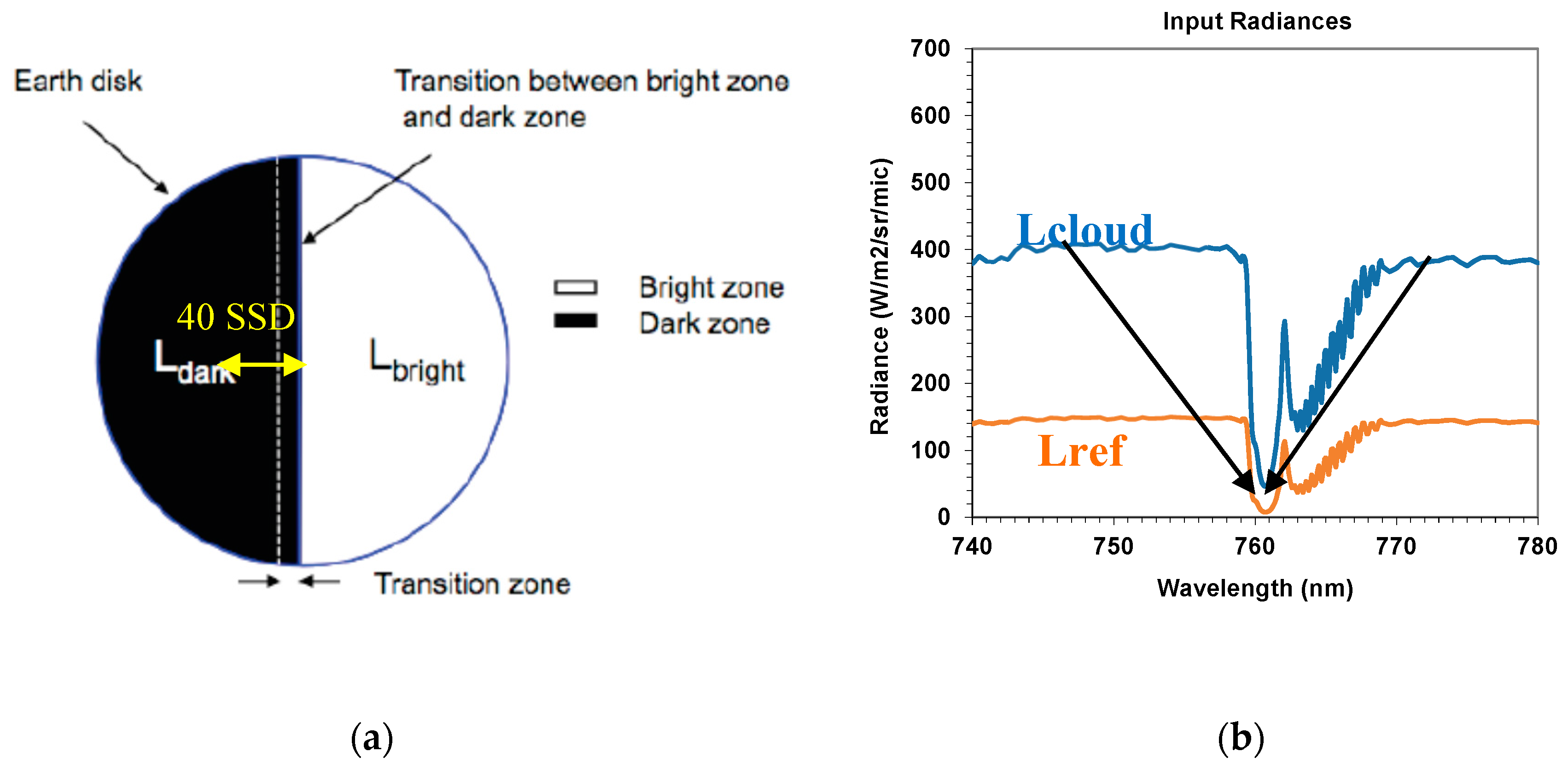
Another fundamental requirement is straylight, which shall be limited (and further reduced with on ground correction algorithms) to avoid pollution of the fluorescence signal. The stray-light signal within the O
2A and O
2B bands at a distance larger than 40 Spatial Sampling Distance (SSD) from the edge of a transition between a bright (e.g., a cloud) and a dark zone (e.g., the reference vegetation) (
Figure 1a) shall be less than 0.04 mW/m
2/sr/nm at level 1b (after straylight correction) and 0.2 mW/m
2/sr/nm at level L0 (without correction). An important contribution is the spectral stray-light, which comes from the light scattered by the spectrometer optical elements (and the gratings in particular) from the continuum bands into the oxygen bands (
Figure 1b). This is affecting measurements even without the presence of bright targets in the scene.
3. Instrument Design
3.1. Instrument Architecture and Optical Design
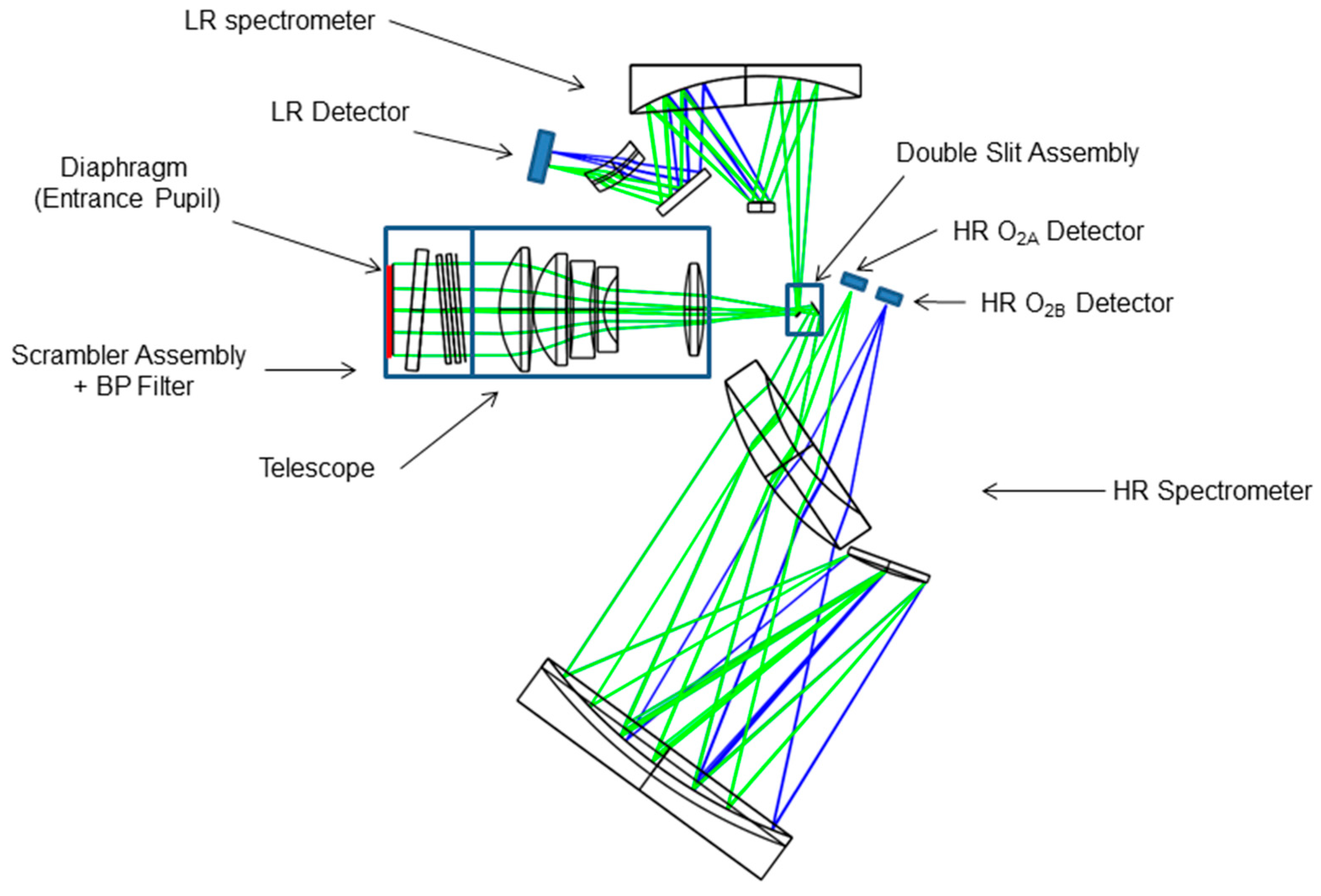
The instrument architecture is based on a push-broom hyperspectral imager with a common telescope and two spectrometers in field separated [
8,
9].
The operational temperature range is 293.15 K ± 2 K. The pupil diameter to comply the SNR requirement is 75.6 mm for HR and 36.1 mm for LR.
A single telescope (234.5 mm of focal length and pupil diameter of 75.6 mm, f-number 3.1) (
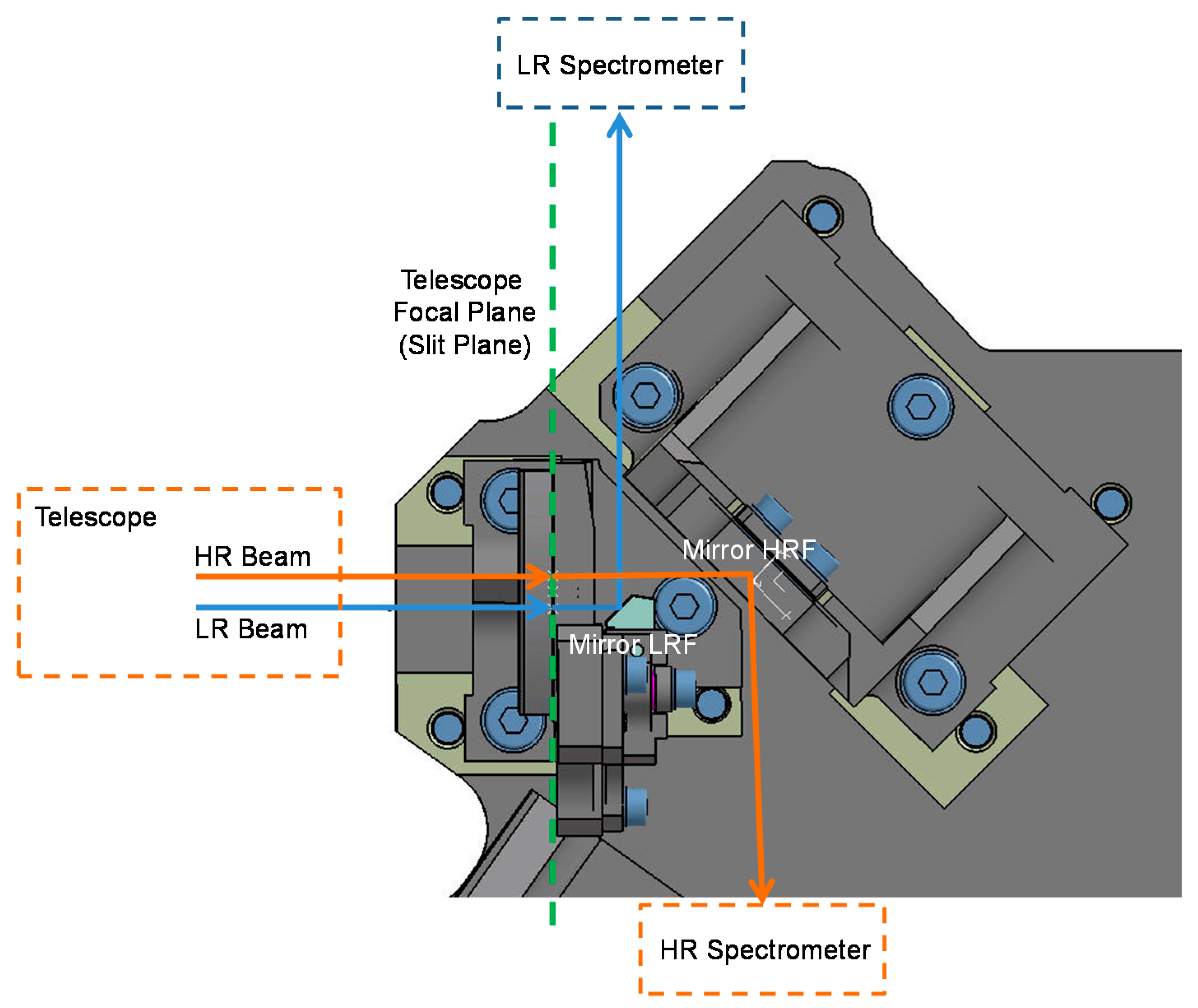
Figure 2) is implemented to collect the radiation coming from two single strips of 300 m × 150 Km onto 2 identical slits (84 μm × 44.1 mm) placed in its focal plane and separated by a distance of 4.5 mm (
Figure 3), corresponding to an on-ground separation of 15.9 km.
The co-registration between the HR and LR bands and the Sentinel 3 data is performed on ground. In front of the telescope an external baffle is placed in order to reduce the out of field straylight. A dual Babinet scrambler is needed to meet the polarization sensitivity requirements. The wedge angle of the scrambler plates is the result of a trade-off between the strength of depolarization and the image quality degradation. The required spectral resolution is obtained by using two modified Offnër spectrometers (
Figure 2). Holographic gratings are used due to the relatively high groove density and because they can guarantee low grating imperfections (residual roughness, profile errors, etc.). This is very important because the gratings are the major contributors of spectral straylight, which directly impact on the fluorescence measurement accuracy within the O
2 absorption band. Three identical low noise backside illuminated frame transfer 1060 × 450 (42 μm spatial ×28 μm spectral) CCD detector units, cooled (−35 °C) by a radiator, allow to cover the three spectral range (O
2B, O
2A and LR bands). The required SNR is achieved by means of a 42.8 ms integration time (300 m on ground) without saturation during cloud observations (full well capacity of 1.25 Me- for each pixel), 1.7 MHz readout frequency, four ports and ×2 pixel binning along the spatial direction at the CCD level. A further binning along the spectral direction (×3 or ×5) can be provided by the Front End Electronics (FEE).
The design approach foresees no aberration compensation between the telescope and the spectrometers to simplify the separate procurement and test of each subsystem. A stabilization of the optical bench of ±1 °C is implemented in order to achieve the required spectral stability. All the materials selected are common for space projects:
Optics: F2G12, Lak9G18, CaF2, BK7G18 for lenses, N-BK7, S-FPL51 for mirrors and Fused Silica for gratings,
Mechanics: Aluminum 6061, Titanium and Invar.
3.2. Telescope
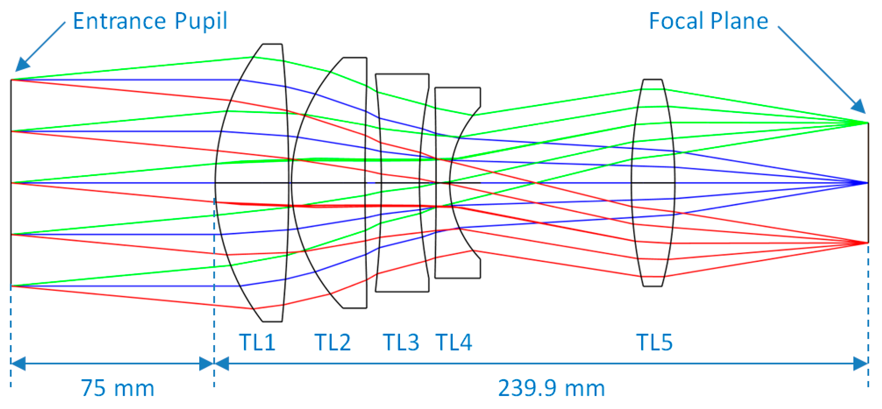
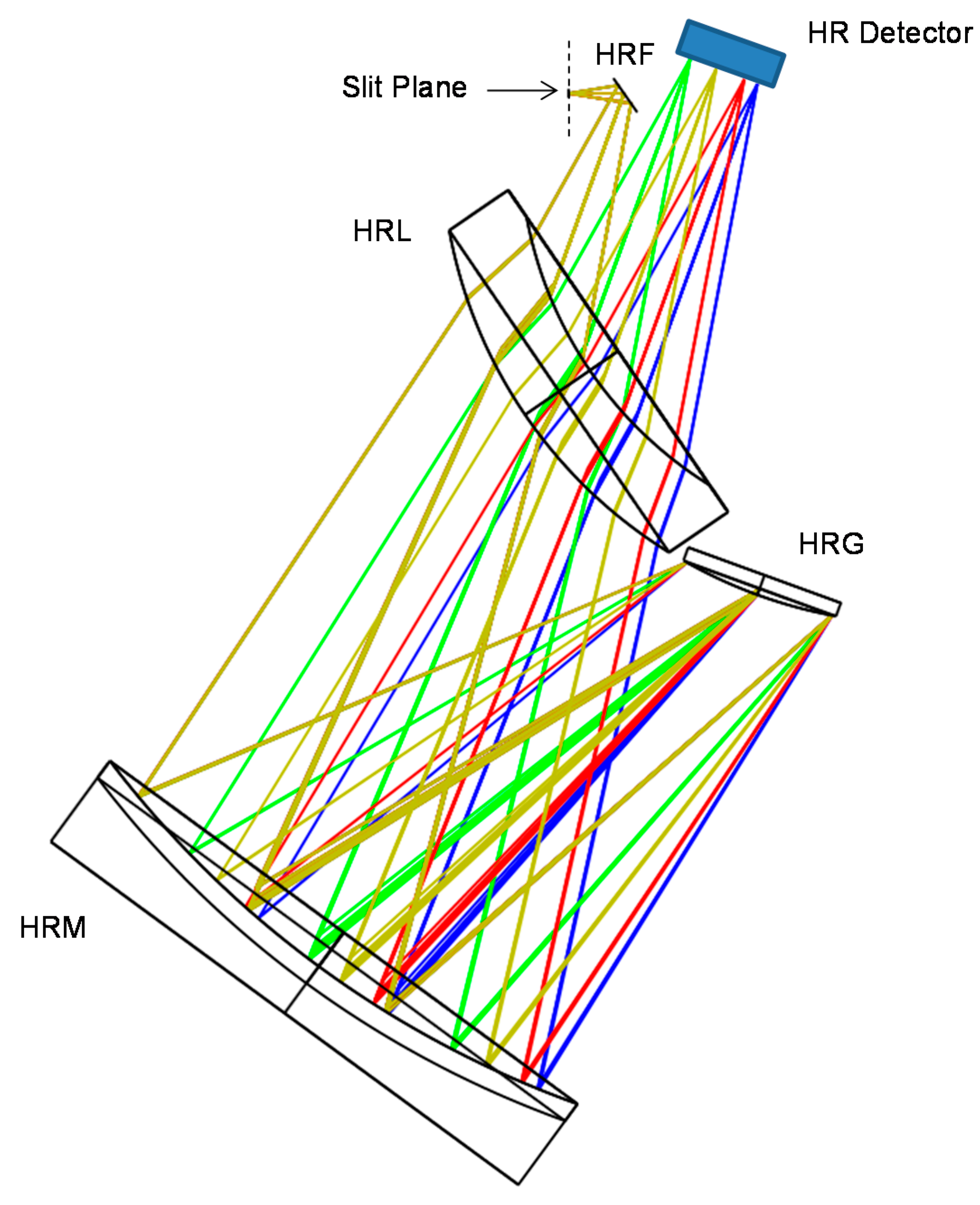
A Petzval objective with 5 lenses (2 aspherical lenses) is used as fore optics (
Figure 4). It has a real entrance pupil located 75 mm in front of the first lens, where the instrument aperture stop is accommodated and it is telecentric in the image focal plane. It guarantees good image quality up to F# = 3.1 in the HR spectral band (FOV = ±5.4° × 0.0°) and to F# = 6.5 in the LR spectral band (FOV = ±5.4° × 1.1°). A smaller F# is needed in the HR spectral band for radiometric constraints (lower input radiance and higher spectral resolution with respect to the LR spectrometer). Chromatic aberration correction is achieved with only three radiation resistant glasses (lateral color <4.7 micron in the HR range and <10.5 micron in the LR one). Radial distortion is less than 0.2% and WFE rms is less than 0.23 waves in HR (0.14 waves in LR) channel by design.
3.3. High Resolution Spectrometer
The proposed solution is based on the Lobb’s theory of concentric designs for grating spectrometer [
10]. It works in the spectral range 670–780 nm with a pixel size of 28 μm in the spectral direction and 84 μm in the spatial one. The F# is the same of the telescope and the magnification is +1.
The starting point is the Offnër relay. Performances of the relay are improved by the addition of a concentric spherical lens through which the light passes twice. The spectrometer is obtained from the relay design by changing the convex spherical mirror with a convex spherical grating [
8]. An additional flat mirror (High Resolution Flat mirror) placed after the HR entrance slit is needed to make easier the HR spectrometer mechanical accommodation and in particular the separation between the slit assembly and the HR detector.
The convex holographic grating has a groove density of 1450 grooves/mm and the average incidence angle on the grating is approximately 38.2°. The −1 order of the diffracted beam is back reflected close to the incident beam, with diffraction angles between 21.3° (at 677 nm) and 30.9° (at 780 nm). This beam is then guided towards the focal plane by means of a second reflection of the concave mirror and the second transmission through the meniscus (
Figure 5). Apart from the zero-order (specular direction) beam which is stopped by a light trap, all other diffraction orders are evanescent [
10]. The use of the high frequency in the grating has two main advantages:
Spectrometer compactness: the larger are the dispersion angles the smaller is the required grating radius of curvature (it corresponds to a lower focal length);
High grating efficiency. Average efficiency greater than 60% can be achieved with an optimized saw-tooth groove profile.
Grating polarization sensitivity is less than 20% and the required grating Bidirectional Reflectance Distribution Function (BRDF), describing the angular distribution of the scattered signal, shall be better than the one of a mirror with a surface roughness of 2 nm rms.
The system gives excellent correction for chromatic aberrations and distortions. This means that the slit images on detector are straight and parallel, falling on detector columns without significant spatial and spectral co-registration errors (keystone less than 0.4 μm and smile less than 0.5 μm by design).
3.4. Low Resolution Spectrometer
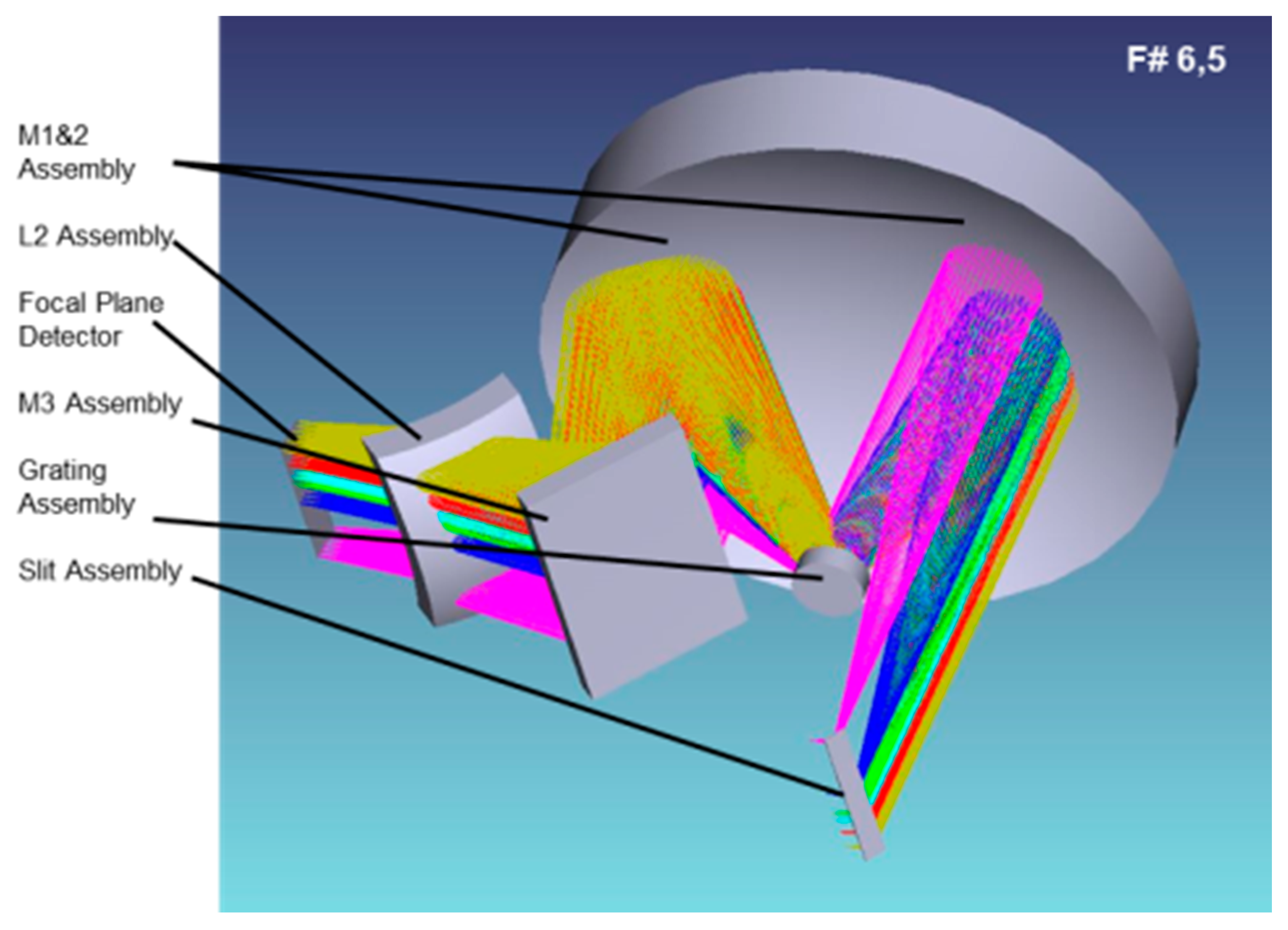
The LR spectrometer optical design is of the same family of the HR one but with a different design of the corrector lens. It works in the spectral range 500–758 nm with a pixel size of 28 μm in the spectral direction and 84 μm in the spatial one. The LR spectrometer works with magnification −1 and its aperture is reduced down to 36.1 mm (f/6.5) by means of a pupil stop placed at the grating plane.
Starting from a standard 2 mirrors Offnër spectrometer, a grating grooves density of 500 lines/mm has been selected in order to achieve the required spectral sampling minimizing the spectrometer size and ghosts due to grating non-operational orders. In order to improve the image quality, a spherical lens has been added. Due to the envelope constraints the design approach of this lens is different from the one used for the HR spectrometer.
The incidence angle on the grating is approximately 17.4°. The beam is diffracted by the first order between 33.2° (at 500 nm) and 41.9° (at 740 nm). The grating is holographic and with a saw-tooth profile. After a second reflection on the primary mirror (M2 has the same radius of curvature of M1) the beam is folded by M3 mirror towards the lens L2 before reaching the focal plane (
Figure 6). The optical quality is almost diffraction limited (WFErms < 0.13 waves) and the correction of distortions is excellent (keystone less than 0.5 μm and smile less than 0.1 μm).
3.5. Detector & Front End Electronics (FEE)
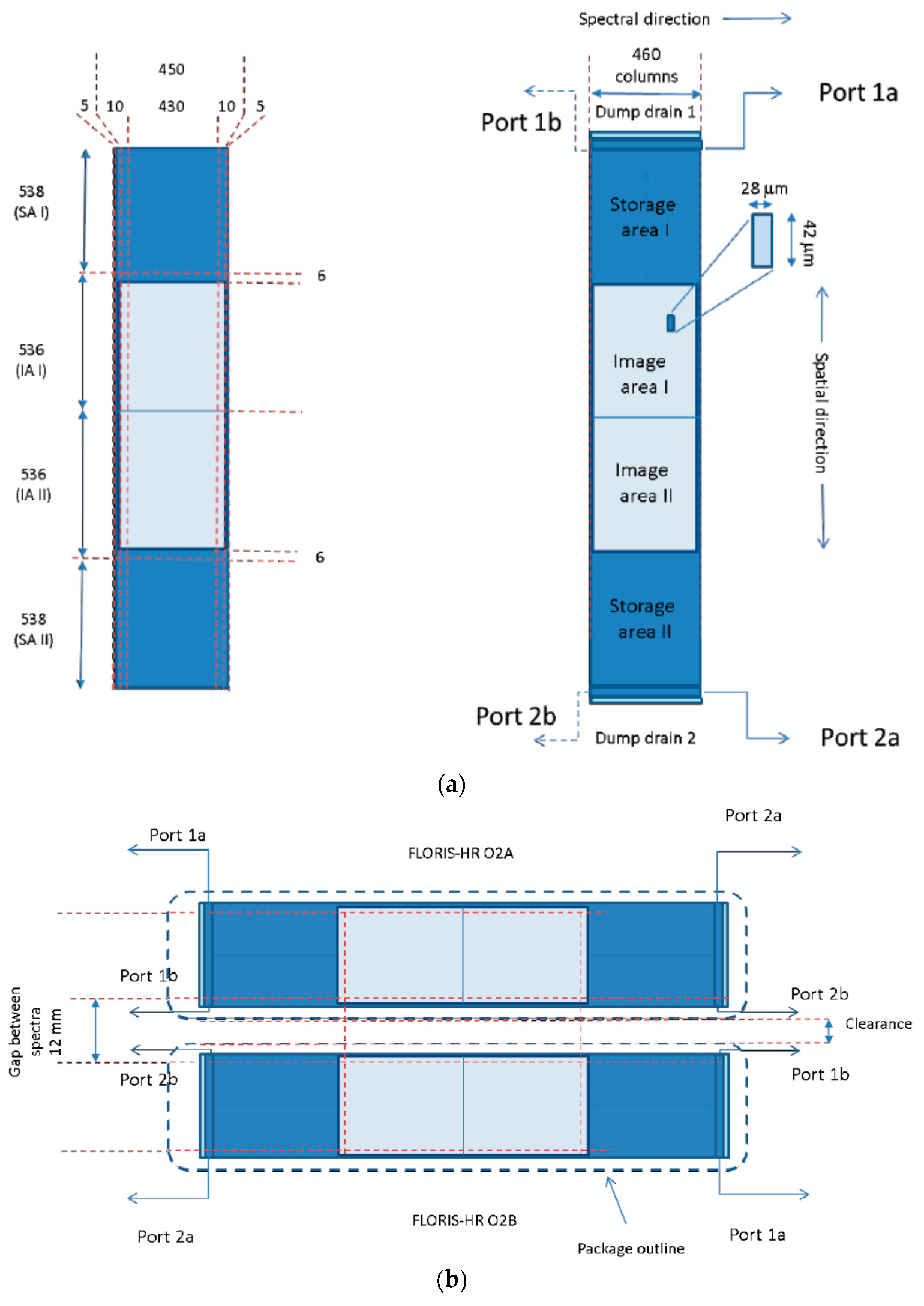
Three identical CCDs (2 for HR and 1 for LR) (
Figure 7a,b), backside illuminated, split frame transfer, radiation tolerant, 4 output ports, 1072 × 460 format with 42 μm × 28 μm (spatial × spectral direction) pixel size and ×2 spatial on-chip binning have been selected. 1050 × 430 (rows × col) will allow the acquisition of 150 km swath and of 40 nm/20 nm spectral range for the O
2A/O
2B bands of HR spectrometer (258 nm for LR). Further 10 × 2 columns and 5 × 2 rows are used as margin for alignment, while 5 × 2 columns and 6 × 2 rows respectively for dark current and smearing signal corrections. The selected format (
Figure 7) with a shorter device width along the spectral direction is selected for a fast row driver (row transfer time < 1.25 μs) in order to reduce the smearing. A 35 micron active silicon thickness with a HfOx 97.9 nm anti-reflection coating has been selected in order to maximize quantum efficiency and minimize reflectivity in the O
2A-O
2B bands, with a max 0.65% of etalon effect (fringing) at 780 nm, which can be corrected by means of a flat field measurement during calibration. 1.7 MHz readout frequency for each port allows download of all pixels at 43.5 ms pixel reading time. The selected gain (0.75 μV/e- for 2.5 Me- Charge Handling Capacitance (CHC) for the ×2 binning pixels) allows measurement of clouds signals both in HR and LR bands for possible in-flight straylight estimation [
11,
12]. The readout noise is reduced with a Correlated Double Sampling (CDS) device in the Front End Electronics (FEE). A dumping gate has been implemented to skip part of swath during the diagnostic mode. In this case all pixels of the swath for a homogeneous target are acquired without binning at different successive times, by using the same CCD timing as the operative mode. The operative detector temperature of 238 K ± 0.10 K (to mitigate the Charge Transfer Efficiency-CTE—degradation due to traps and to increase radiometric stability) is achieved by using an external radiator & heater/sensor near the package. No window is foreseen in order to avoid multi-reflections with the anti-reflection coating placed on the detector sensible area. Two adjacent detectors (
Figure 7b) are placed in the HR focal plane along the spectral direction and separated of a distance less than 12.06 mm in order to cover the two O
2 absorption bands (677–697 nm and 740–780 nm).
The Front End Electronic (FEE) is split into two parts: the Focal Plane Proximity Electronics (FPPE) devoted to pre-amplification and CCD bias conditioning, and the Video Acquisition Unit (VAU) for gain/offset drift compensation, bias and clocks generation/driving, FEE Telemetry (TM)/Telecommand (TC) and digital processing/serializing. The FPPE is placed at 5 cm from the detector while the VAU is at a distance of about 20–30 cm from FPPE. A 3 MHz Analog to Digital Converter (ADC) working at 16 bit with about 1.6 LSB total noise and three space-wire links versus nominal/redundant Main Electronics (ME) are used.
4. Mechanical Layout
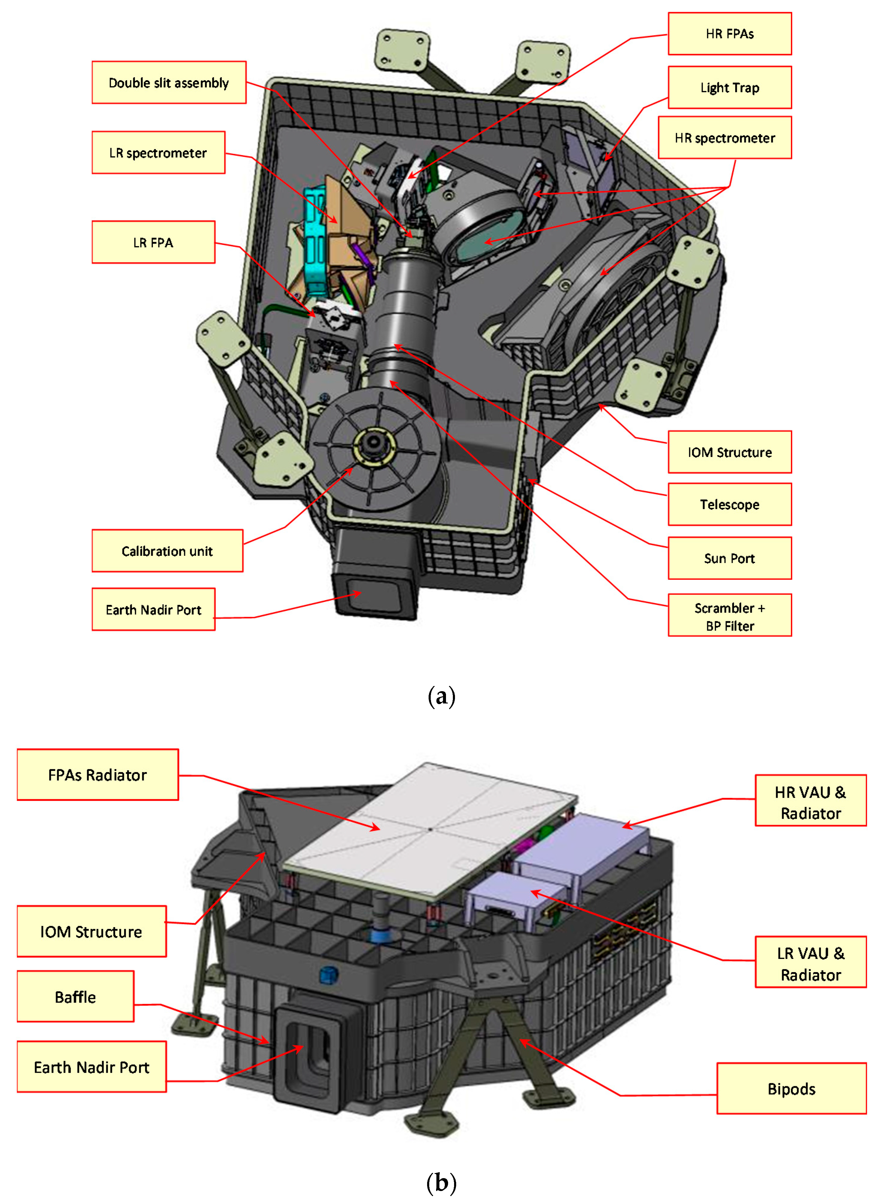
The optical Bench is in Al6061 T6 with optics holders in Titanium or Aluminium for high thermal insulation & stability (
Figure 8a). The Earth nadir baffle is also in aluminum and it is divided in three parts: an external fixed one, an internal one within the calibration unit and another internal fixed one in front of the scrambler/Band Pass (BP) filter device. Three white painted radiators cooling the detectors and the VAU’s are mounted on the upper side of instrument (
Figure 8b), with a full view to the cold space for optimum SpaceCraft (S/C) accommodation & thermal efficiency. The isostatic mount concept with three titanium bipods at 120 degrees assures the mechanical stability (
Figure 8a). The ME is separated by the instrument and is mounted on the S/C payload module.
5. Instrument Calibration
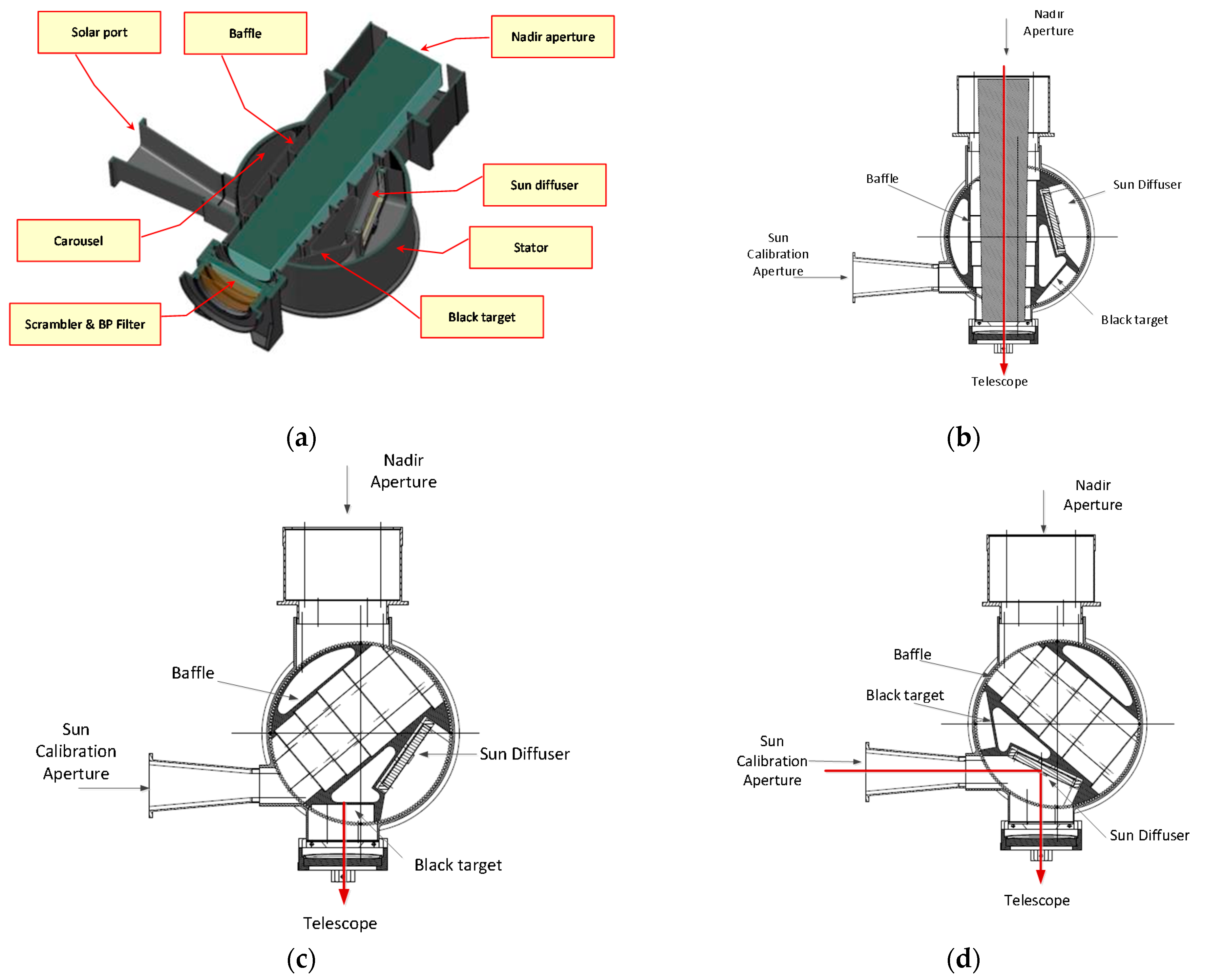
The spectral calibration is performed on ground during pre-launch activities and will be checked/updated in-flight by means of vicarious techniques using the measurement of the atmospheric gas and/or the sun Fraunhofer lines. In flight radiometric calibration is obtained with a two points calibration scheme. A Sun illuminated reflection diffuser (of Spectralon with ρ =100%, θinc. = 65°) is observed every 7–15 days at South Pole, while a dark reference, useful for dark current and electronic offset data, is measured every 2–3 orbits. A satellite slew of 30° is planned for the sun observation. The calibration unit is composed by a carousel (
Figure 9a) which can rotate in three different positions. The first one, relevant to the nominal observation (Nadir), allows telescope pupil illumination by the light coming from the front aperture through the nadir baffle (
Figure 9b), the second one presents black flat target at the telescope input for instrument dark calibration (
Figure 9c), and the last one allows the sun calibration by observing a Sun-illuminated reference stable reflection diffuser with the Sun entering into the instrument by the solar port placed on the lateral side (
Figure 9d).
During almost all operations after instrument delivery (calibration and satellite Assembly, Integration and Verification-AIV—activities), the launch, the Earth observation and the dark calibration, the diffuser remains enclosed in a small room, protected from possible external and internal contaminations. Only during the solar calibration the diffuser is placed in the calibration position, with sun entering through the solar port.
6. On Ground Calibration/Validation Activities
The methodology used to verify instrument performance on-ground encompasses the characterization of components and subsystems during the instrument build/integration and the calibration/characterization/validation of the instrument.
The key performance criteria of components, items, and subsystems is established at various stages of instrument development so that the relevant geometric, radiometric, spectral, polarization and straylight properties are determined to verify all governing requirements during the pre-flight assembly, integration, test and calibration of the instrument. On-ground instrument calibration/characterization/validation will be performed in facilities designed to simulate the on-orbit environment using specific Ground Support Equipments (GSEs). Instrument level alignment and a reduced test campaign before and after instrument qualification will be performed at Leonardo site. Full geometric calibration as well as spectral, polarimetric, radiometric and straylight test and calibration will be performed at the calibrator facility. The calibration data, generated during on-ground calibration, will be used as the reference calibration of FLORIS when it begins its on-orbit mission. Subsequent in-flight calibration campaigns will be used to monitor and update the calibration parameters throughout the mission.
The geometric calibration includes the Instrument Spatial Response (called System Energy Distribution Function, SEDF) characterization and the determination of alignment parameters relevant for instrument pointing knowledge when integrated on S/C and then in flight with respect to earth/sun target. Also spatial co-registration measurements for each and between HR and LR channels will be performed.
The spectral calibration includes the measurement of Instrument Spectral Response Function (ISRF) shape, Spectral Sampling Interval (SSI), Spectral Resolution (SR), Smile, Calibration Unit (CU) spectral features.
Radiometric Calibration measures the instrument radiometric response in all spectral bands. It includes radiance calibration coefficients, response linearity, noise, detector Pixel-to-pixel Response Non-Uniformity (PRNU), detector Dark Signal Non-Uniformity (DSNU), etc. Radiometric calibration shall also include a characterization of the instrument response through the sun calibration port versus sun angle at instrument level. The radiometric calibration is performed using fully and partial linearly polarized light and fully unpolarized light.
Straylight is an important characterization and calibration parameter as the levels of straylight at various scene/radiance conditions contribute to errors in the radiometric accuracy of the instrument and in the fluorescence retrieval algorithm. Straylight assessment is one of the most challenging tasks of calibration and requires a combination of methods including point source and/or extended target stimulus in order to simulate extended non-uniform scenes.
7. Performance
The more stringent requirement for the Spectral Resolution (SR = 0.3 nm) is relevant to the two HR O
2 absorption bands 686–697 nm and 759–769 nm (
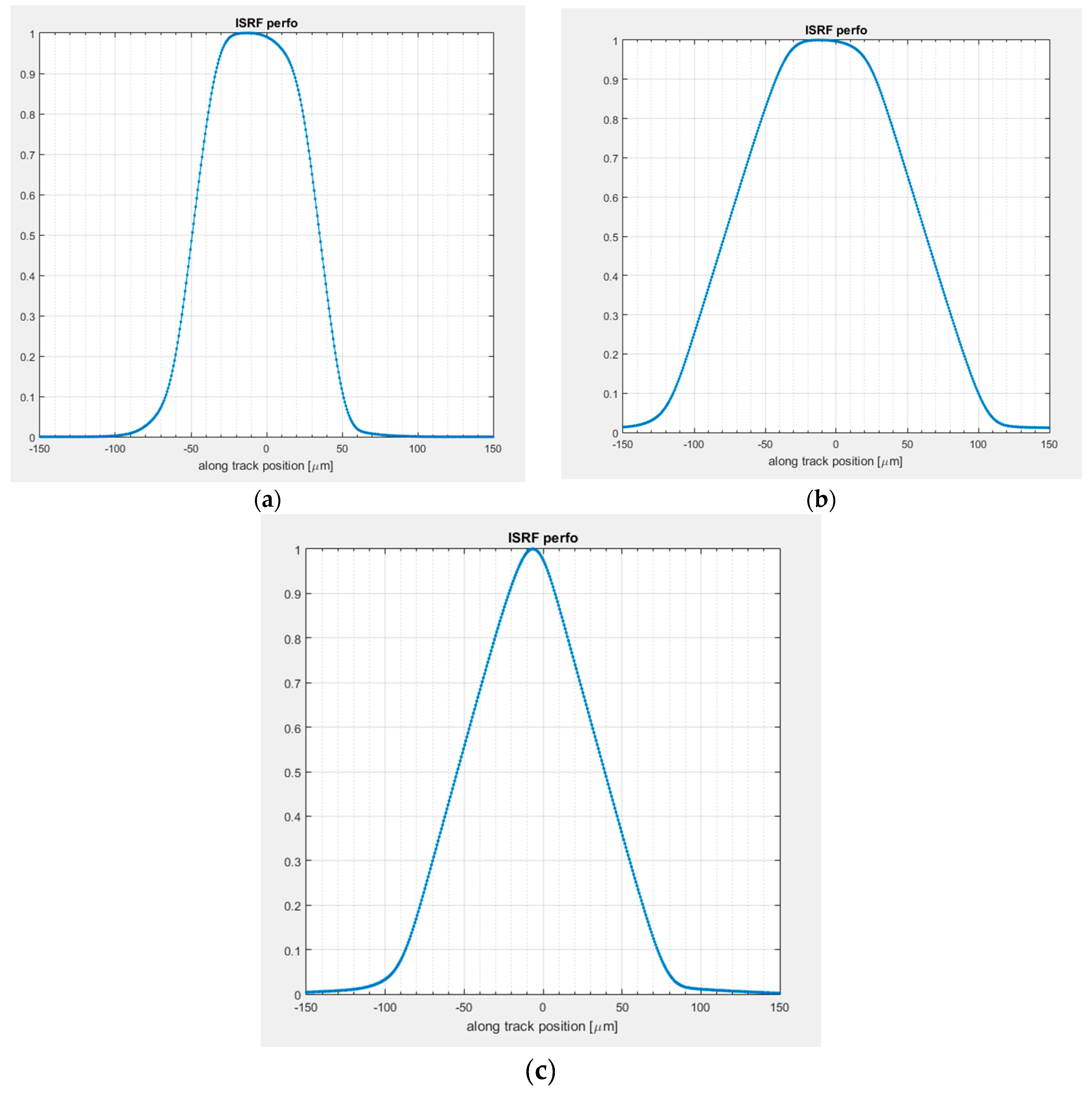
Table 2). This has been achieved by using a slit width of three times (84 μm) the pixel sampling interval (28 μm). A similar concept has been applied for the LR 697–758 nm band. For these HR and LR bands the Spectral Resolution is principally driven by the slit width (
Figure 10a). The other HR bands (677–686 nm, 740–759 nm and 769–780 nm) have been obtained by means of ×5 spectral binning performed at VAU level, with a spectral resolution principally driven from the aggregated pixel size (140 μm) (
Figure 10b,
Table 2). The remaining LR bands (500–697 nm) have been obtained by means of x3 spectral binning at VAU level, with a spectral sampling equal to the slit with (84 μm) (
Figure 10c). Finally the Instrument Spectral Response Function (ISRF) is a quasi-trapezoidal function for almost all bands and a quasi-triangular function for the LR 500–697 nm bands (
Figure 10a–c). In fact, considering the achieved optical quality, the ISRF can be principally obtained by a convolution between two rectangular functions, representing the slit width of 84 μm and the spectral pixel size after binning ×1, ×3 or ×5, corresponding respectively to 28 μm (
Figure 10a), 84 μm (
Figure 10c) and 140 μm (
Figure 10b).
The Image quality has been evaluated from the Full Width Half Maximum (FWHM) of the System Energy Distribution Function (SEDF), which represents the spatial response of the optical system to a spectrally uniform point source. A system Modulation Transfer Function (MTF) budget has been performed taking into account the following End-Of-Life (EOL) contributions for the across and/or the along track directions: scrambler, telescope, slit, spectrometer, detector pixel response (incl. cross-talk and Charge Transfer Efficiency), pixel integration along motion and jitter (instrument and satellite). Then the SEDF has been obtained (
Figure 11a) from the inverse Fourier Transform of the system MTF. The FWHM of SEDF in the across and along track directions (
Figure 11b) are respectively 95.6 μm (along-track) and 88.7 μm (across-track) corresponding respectively to 1.14 SSD and 1.06 SSD (with SSD = Spatial Sampling Distance = 84 μm).
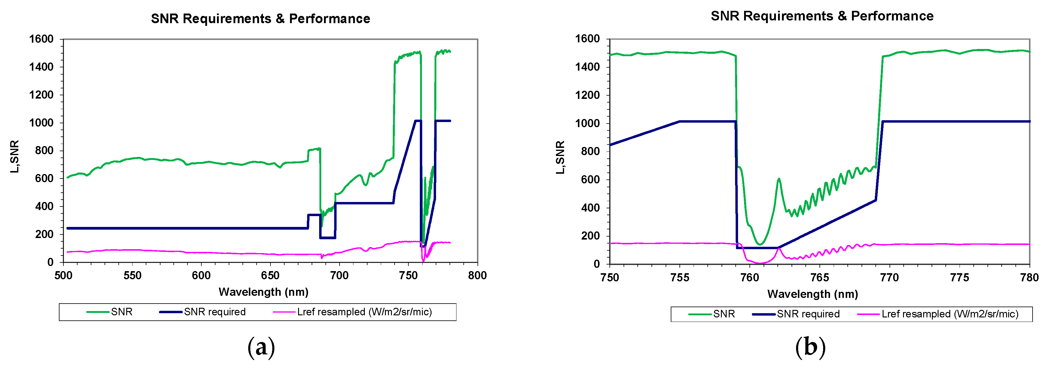
The combination of a high SNR and a high spectral sampling requirement asks for a demanding instrument in terms of the smearing noise (row transfer frequency = 0.8 MHz), pupil diameter (75.6 mm) and optics transmission (37%). The pupil diameter is about three times higher with respect to that of the OLCI spectrometer embarked on Sentinel 3 platform and the previous MERIS (on Envisat), which has a similar on ground sampling (300 m) and integration time (45 ms) but a more relaxed spectral sampling interval and spectral resolution (about 10–20 times). The comparison between SNR requirement and performance are reported in
Figure 12. The minimum SNR performance is 125 at 760.7 nm with SSI of 0.093 nm, compliant with requirement (SNR = 111) with a margin of +12%.
Considering that the slit represents an intermediate field stop of the system, the total instrument stray-light can be divided in two terms, one coming from the telescope and the other coming from the spectrometer. In both cases the main stray-light contributions are the scattering coming from the surface roughness of the opto-mechanical elements, the scattering coming from the distributed PArticle Contamination (PAC) and the ghosts. Optical design is based on very demanding roughness values (0.5 ÷ 1.5 nm rms for lenses and mirrors, 2.5 nm for scrambler and 2 nm for grating), low AR coatings reflectivity (0.5−1.5%), including the detector retina, high grating efficiency (>60%) and high mirror reflectivity (98.5%). Moreover contamination will be taken under control for the overall Assembly, Integration and Test (AIT) and Assembly, Integration and Verification (AIV) activities in order to achieve challenging values of EOL PAC (250 ppm for the first surface, 35 ppm for scrambler assembly and telescope inner surfaces and 150 ppm for all others components).
Mitigation actions will be adopted by preventing the increase of contaminants: operations in ISO 5 classroom with contamination control and cleaning of exposed surfaces (if necessary) for all the main assemblies up to the delivery to satellite prime, use of a quasi-hermetic cover and closer of carousel during almost all AIT/AIV activities at satellite site, purging with dry nitrogen during activities in which the instrument will not be in a controlled environment (long storage periods, vibration tests, route from a cleanroom to another, and other activities at satellite site), use of dedicated snorkels (cold space oriented) in the design in order to facilitate on-orbit de-contamination.
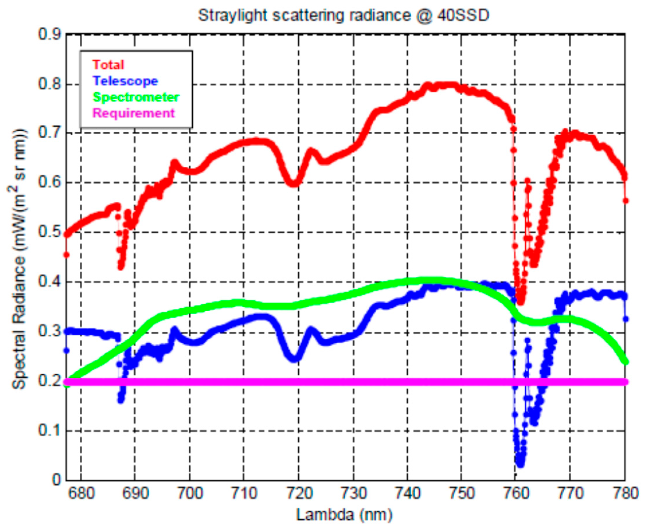
Actual performance (
Figure 13) are higher with respect to level L0 requirement (0.2 mW/m
2/sr/nm) of about a factor 4, meaning that the requirement at level 1b (0.04 mW/m
2/sr/nm) will be obtained only after a dedicated on-ground stray-light measurement campaign and model correction activity (similar to that performed for OLCI on Sentinel 3). In-flight verification by measuring the transition between a cloud and a vegetated target and/or by observing the transition between moon and cold space are also planned.
8. FLORIS Elegant Breadboard
The FLEX pre-development has been addressed from the very beginning by ESA toward an experimental validation of the optical concept, the related alignment and test procedures and the early risk retirement of the most critical technologies as for instance detectors and gratings. An extensive breadboard development has been initiated since the phase A/B1 study of the mission, and its refurbishment is currently in progress for an Elegant BreadBoard (EBB). The current status of the breadboard includes the optical bench, the common telescope and the HR spectrometer. Service detectors with a pixel size comparable to the flight ones are implemented in the breadboard (
Figure 14). The breadboard has been recently tested confirming the good optical quality of the design [
13]. A new test campaign is currently in preparation in cleanroom ISO 5 to perform a better straylight characterization. The breadboard will be then refurbished with the inclusion of the polarization scrambler and the LR spectrometer and a new measurement campaign is planned.
9. Conclusions
The optical design, the required and the foreseen performance of the FLORIS instrument have been presented. The baseline is a very compact, robust, stable versus temperature and easy to align optical design. Good performance is achieved in terms of optical quality, distortions (keystone and smile) and Signal to Noise Ratio in the whole field of view and spectral range. The common fore-optics and the double slit assembly assure an optimum spatial co-registration stability by design between the spectral channels. Particular attention has been also devoted to the reduction of the stray-light effects by using efficient coatings, holographic gratings, low roughness for each optical elements and particular attention to the instrument contamination level. The adopted Offnёr solutions for the spectrometers have a large heritage in Leonardo [
14,
15,
16]. The CCD detector design is not critical from a technological point of view and a breadboard activity is on-going. The same format has been chosen for all the three focal planes in order to reduce smearing and achieve an high pixel capacitance with low noise, no Peltier stage and pixels devoted to smearing and dark current corrections in flight. A simple mechanical layout in a monolithic aluminum optical bench allows the use of isostatic mounts and a good thermal stabilization by means of radiators looking at the cold space view and heaters.
10. Outlook
The FLEX tandem mission concept with its highly innovative FLORIS payload will provide unprecedented information on the functioning of vegetation, actual photosynthetic efficiency and health status. The primary data products contain quality controlled, spectrally and geometrically characterized and radiometrically calibrated TOA radiances that will be made available to the users within 24 h of sensing. Higher-level scientific data products comprise TOA synergy data sets from OLCI, SLSTR and FLORIS as well as fluorescence emission in the oxygen absorption lines, the spectrally integrated total fluorescence emission and the peak values around 680 nm and 740 nm [
4]. The validation of these products follows the recommendations of the Committee on Earth Observation Satellites (CEOS) in that ground truth measurements at top of canopy will be up-scaled to the FLEX spatial resolution. The corresponding infrastructure at ground will be developed, tested, and implemented during the coming years.
As an Earth Explorer mission, FLEX can serve as a vanguard for a future operational mission supporting a large variety of services. Potential application areas comprise forest health monitoring, early detection and warning of stress-induced strain in perennial food crops, evaluation of land-use management strategies, or phenotyping assessments of food and feed crops. In coastal areas, there is the potential for using the observations to detect and track toxic algal blooms.
