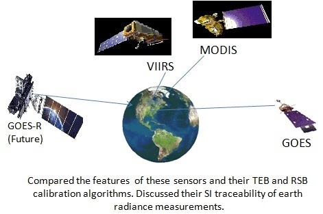
Comparison of the Calibration Algorithms and SI Traceability of MODIS, VIIRS, GOES, and GOES-R ABI Sensors


Abstract
:
1. Introduction
Measurement Equation and Calibration Equations
2. Methods of Radiometric Calibration—Polar Satellite Sensors
2.1. MODIS
2.1.1. MODIS TEB Radiometric Calibration
- is the emissivity of the BB (Pre-launch characterization).
- is the radiance from the BB at its set temperature. It is the averaged over the RSR.
- is the radiance of the scan mirror at its temperature.
- is the emissivity of the cavity formed by the housing of all the optics (Pre-launch Characterization).
- is the radiance of the scan housing that acts as a cavity emitting radiation based on its temperature.
- is the normalized system response versus scan angle when the sensor views the BB.
- is the radiance from the common path background.
2.1.2. MODIS RSB Radiometric Calibration
2.1.3. Analysis of the MODIS Calibration Algorithm and SI Traceability
2.2. VIIRS
2.2.1. VIIRS TEB Radiometric Calibration
2.2.2. VIIRS Radiometric RSB Calibration
2.2.3. Analysis of the VIIRS Calibration Algorithm and SI Traceability
3. Methods of Radiometric Calibration—Geostationary Satellite Sensors
3.1. GOES Imager
3.1.1. GOES TEB Radiometric Calibration
3.1.2. GOES Visible Band (0.55–0.75 µm) Radiometric Calibration
3.1.3. Analysis of the GOES Calibration Algorithm and SI Traceability
3.2. GOES-R Advanced Baseline Imager (ABI)
3.2.1. GOES-R ABI TEB Radiometric Calibration
3.2.2. GOES-R ABI RSB Radiometric Calibration
3.2.3. Analysis of the GOES-R ABI Calibration Algorithm and SI Traceability
4. Discussion—Comparison of the Spectral Bands and Their Calibration Features of the Four Sensors, MODIS, VIIRS, GOES and GOES-R ABI
4.1. Comparison of Spectral Bands

| VIIRS Band | Central Wavelength (µm) | Wavelength Range (µm) | Nadir HSR (m) | Primary Use | MODIS Equal Band(s) | Central Wavelength (µm) | Wavelength Range (µm) | Nadir HSR (m) |
|---|---|---|---|---|---|---|---|---|
| M1 | 0.412 | 0.402–0.422 | 750 | Ocean color Aerosals | 8 | 0.4113 | 0.405–0.420 | 1000 |
| M2 | 0.445 | 0.436–0.454 | 750 | Ocean color Aerosals | 9 | 0.442 | 0.438–0.448 | 1000 |
| M3 | 0.488 | 0.478–0.488 | 750 | Ocean color Aerosals | 3 | 0.4656 | 0.459–0.479 | 500 |
| 10 | 0.4869 | 0.483–0.493 | 1000 | |||||
| M4 | 0.555 | 0.545–0.565 | 750 | Ocean color Aerosals | 4 | 0.5536 | 0.545–0.565 | 500 |
| 12 | 0.5468 | 0.546–0.556 | 1000 | |||||
| M5 | 0.672 | 0.662–0.682 | 750 | Ocean color Aerosals | 13 | 0.6655 | 0.662–0.672 | 1000 |
| 14 | 0.6768 | 0.673–0.683 | 1000 | |||||
| M6 | 0.746 | 0.739–0.754 | 750 | Atmospheric Correction | 15 | 0.7464 | 0.743–0.753 | 1000 |
| M7 | 0.865 | 0.846–0.885 | 750 | Ocean color Aerosals | 16 | 0.8662 | 0.862–0.877 | 1000 |
| M8 | 1.240 | 1.23–1.25 | 750 | Cloud Particle size | 5 | 1.2416 | 1.23–1.25 | 500 |
| M9 | 1.378 | 1.371–1.386 | 750 | Cirrus/Cloud Cover | 26 | 1.38 | 1.36–1.39 | 1000 |
| M10 | 1.61 | 1.58–1.64 | 750 | Snow Fraction | 6 | 1.629 | 1.628–1.652 | 500 |
| M11 | 2.25 | 2.23–2.28 | 750 | Clouds | 7 | 2.114 | 2.105–2.155 | 500 |
| M12 | 3.7 | 3.61–3.79 | 750 | Sea Surface Temperature (SST) | 20 | 3.79 | 3.66–3.84 | 1000 |
| M13 | 4.05 | 3.97–4.13 | 750 | SST/Fires | 21 | 3.96 | 3.929–3.989 | 1000 |
| 22 | 3.96 | 3.929–3.989 | 1000 | |||||
| 23 | 4.06 | 4.02–4.08 | 1000 | |||||
| M14 | 8.55 | 8.4–8.7 | 750 | Cloud Top Properties | 29 | 8.52 | 8.4–8.7 | 1000 |
| M15 | 10.763 | 10.26–11.26 | 750 | SST | 31 | 11.02 | 10.78–11.28 | 1000 |
| M16 | 12.013 | 11.54–12.49 | 750 | SST | 32 | 12.03 | 11.77–12.27 | 1000 |
| VIIRS Band | Central Wavelength (µm) | Wavelength Range (µm) | Nadir HSR (m) | Primary Use | MODIS Equal Band (s) | Central Wavelength (µm) | Wavelength Range (µm) | Nadir HSR (m) |
|---|---|---|---|---|---|---|---|---|
| DNB | 0.7 | 0.5–0.9 | 750 (across full scan) | Imagery | ||||
| I1 | 0.64 | 0.6–0.68 | 375 | Imagery | 1 | 0.6455 | 0.62–0.67 | 250 |
| I2 | 0.865 | 0.85–0.88 | 375 | NDVI | 2 | 0.8565 | 0.841–0.876 | 250 |
| I3 | 1.61 | 1.58–1.64 | 375 | Binary Snow Map | 6 | 1.6291 | 1.628–1.652 | 500 |
| I4 | 3.74 | 3.55–3.93 | 375 | Imagery of Clouds | 20 | 3.79 | 3.66–3.84 | 1000 |
| I5 | 11.45 | 10.5–12.4 | 375 | Imagery of Clouds | 31 | 11.02 | 10.78–11.28 | 1000 |
| 32 | 12.03 | 11.77–12.27 | 1000 |
| ABI Band | Wavelength Range (µm) | Central Wavelength (µm) | IGFOV (km) | Primary Use | Heritage Instrument (s) |
|---|---|---|---|---|---|
| 1 | 0.45–0.49 | 0.47 | 1 | Daytime aerosol land, coastal water mapping | MODIS B 3 and B 10; VIIRS M3 |
| 2 | 0.59–0.69 | 0.64 | 0.5 | Daytime Clouds, fog, Insolation, winds | Current GOES Imager; Sounder |
| 3 | 0.846–0.885 | 0.865 | 1 | Vegetation/ burn scar and aerosol over water, winds | VIIRS I2; MODIS B 2 |
| 4 | 1.371–1.386 | 1.378 | 2 | Daytime Cirrus Cloud | VIIRS M9; MODIS B 26 |
| 5 | 1.58–1.64 | 1.61 | 1 | Daytime Cloud-top Phase and particle size, snow | VIIRS I3 and M10; MODIS B 6 |
| 6 | 2.225–2.275 | 2.25 | 2 | Daytime land/cloud properties, particle size, vegetation, snow | VIIRS M11; MODIS B 7 |
| 7 | 3.80–4.00 | 3.9 | 2 | Surface and Cloud, fog at night, fire and winds | Current GOES Imager |
| 8 | 5.77–6.6 | 6.19 | 2 | High-level atmospheric water vapor, winds, rainfall | Current GOES Imager |
| 9 | 6.75–7.15 | 6.95 | 2 | Mid-level atmospheric water vapor, winds and rainfall | Current GOES Sounder |
| 10 | 7.24–7.44 | 7.34 | 2 | Lower-level water vapor, winds, rainfall | Current GOES Sounder |
| 11 | 8.3–8.7 | 8.5 | 2 | Total water for stability, cloud phase, dust, SO2 | VIIRS M14; MODIS B 29 |
| 12 | 9.42–9.8 | 9.61 | 2 | Total Ozone, Turbulence and winds | Current GOES Sounder |
| 13 | 10.1–10.6 | 10.35 | 2 | Surface and Cloud | VIIRS M15; MODIS B 31 |
| 14 | 10.8–11.6 | 11.2 | 2 | Imagery, SST, Clouds and rainfall | Current GOES Sounder |
| 15 | 11.8–12.8 | 12.3 | 2 | Total water, ash, and SST | Current GOES Sounder |
| 16 | 13.0–13.6 | 13.3 | 2 | Air temperature, cloud heights and amounts; CO2 | Current GOES Imager; Current GOES Sounder |
4.2. Comparison of Sensor Features for Calibration and On-Orbit Observations
| MODIS | VIIRS | GOES Imager | GOES-R ABI |
|---|---|---|---|
| Passive Cross-track imaging radiometer | Passive Cross-track imaging radiometer | Passive staring imaging radiometer | Passive staring imaging radiometer |
| Two sided beryllium paddle wheel scan mirror continually rotates at 20.3 rpm (1.478 s for each mirror side). | Scanning telescope: RTA (Rotating telescope assembly) projecting on to a half angle mirror (HAM). The RTA continuously rotates at constant speed taking 1.7864 s per revolution and is synchronized with the HAM once per scan. | Scan mirror that alternately sweeps east to west and west to east perpendicular to a north south path to direct the beam to a Casegrain telescope. Full disk scan interval 30 min | N/S scanning mirror reflection scanned by E/W mirror to the fore-optics (Off-Axis Four Mirror Assembly (FMA) Telescope. Independent N/S and E/W scanners. E/W raster scan rate 1.4 degree/Section Full disk scan interval 5 min. |
| Feature | MODIS | VIIRS | GOES Imager | GOES-R ABI |
|---|---|---|---|---|
| Instrumentation temperature dependency | Yes | Yes | No (Calibration algorithm). Yes (for corrections) | No |
| Scan mirror Radiance considered | Yes | Yes | Yes | Yes (Both East/West and North/South mirrors) |
| Scan mirror housing cavity | Yes | Yes | No | No |
| Telescope Radiance considered | No Need | Yes | No Need | No Need |
| Calibration function | Quadratic with offset | Quadratic with offset | Quadratic with offset (before space view subtraction) | Quadratic (Offset cancelled by space view) |
| On-orbit Calibration Coefficients updated | Linear coefficient (Offset and non-linear terms from LUTs updated from on orbit BB warm up and cool down cycles) | Scale Factor F to update calibration coefficients provided in the LUTs (Offset and non-linear terms from LUTs updated from on orbit BB warm up and cool down cycles) | Calibration coefficients determined on orbit | Linear Coefficient is updated and LUT provides quadratic coefficient and no offset |
| Spectral Response Function (SRF) | Pre-launch | Pre-launch | Prelaunch (Corrections using GSICS LEO comparison [31,32] | Pre-launch |
| Band averaged spectral radiance | LUT generated using SRF | LUT generated using SRF | Approximate formulas generated using Planck and SRF. | LUT generated using SRF |
| Response versus mirror scan angle | Pre-launch Post-launch verification–Update once done for TERRA Deep Space maneuver) | Pre-launch and on-orbit verification (Pitch Maneuver) | Determined using on orbit space look data at various angles and laboratory witness sample data for 45° scan angle. | Pre-launch (potential on-orbit verification) |
| Calibration Interval | Scan-by scan | Scan-by-scan for single Gain bands. Dual gain M13 band Low gain LUT on-orbit update. | Blackbody 30 minutes; Space view 2.2 s, or 36.6 s | 5–15 min |
| Feature | MODIS | VIIRS | GOES Imager | GOES-R ABI |
|---|---|---|---|---|
| Instrumentation temperature dependency | Yes | Yes | No | No |
| Detector temperature dependency | Yes (detector temperatures are correlated with instrument temperatures) | Yes | No | No |
| Calibration function | Linear without offset | Quadratic with offset | Linear with offset | Quadratic (Offset cancelled by space view) |
| On-orbit Calibration Coefficient | Linear coefficient based on calibration by Solar Diffuser | Scale Factor F using Solar Diffuser calibration to update Calibration coefficients provided in the LUTs | Calibration coefficients are being updated monthly by vicarious calibration using collocated Terra MODIS cloud observations since 2005. | Linear Coefficient using solar Diffuser Calibration and also using LUT |
| Spectroradiometric Calibration assembly Sector (SRCA) | Yes | No | No | No |
| Spectral Response Function (SRF) | Pre-launch and on orbit verification using SRCA | Pre-launch | Prelaunch | Pre-launch |
| Response versus mirror scan angle | Post Launch on–orbit using moon or earth view | Pre-launch (Pitch maneuver—on-orbit verification) | No | Pre-launch (potential on-orbit verification) |
| Lunar Calibration | Yes | Yes | Yes | Yes |
| Solar Diffuser Stability Monitor (SDSM) | Yes | Yes | Not Applicable as No Solar Diffuser | No |
| Solar Diffuser (SD) Calibration Interval | Weekly to tri-weekly | Daily | No SD | Weekly to monthly |
| SD–Vignette Function (VF) of Partial Aperture (PA) | Averaged VF Pre-launch, and on-orbit verification | Band-dependent VF Pre-launch (Updated on orbit) | No SD | Partial Aperture Pre-launch |
| Solar Irradiance data | 3 data sets; (0.4 to 0.8 µm [46]; 0.8 to 1.1 µm [47]; Above 1.1 µm [48]. | MODTRAN 4.3 [49] | Bishop and Rossow [50] | 4 data sets; 0.4 to 1.2 µm [47]), 033 to 1.25 µm [50]; 1.2 to 100 µm [51]; 0.2 to 10.1 µm, [52]. |
5. Conclusions
Acknowledgments
Author Contributions
Conflicts of Interest
Appendix
| Terminology | Symbols | |||
|---|---|---|---|---|
| MODIS | VIIRS | GOES/Imager | GOES-R ABI | |
| Radiance | L | L | R | L |
| Detector output (counts) used in the Calibration equation | The difference in counts between sensor view of an object and space view. | The difference in counts between sensor view of an object and space view. | Detector response in Counts. | The difference in counts between sensor view of an object and space view. |
| (SV = Space View) | X | |||
References
- Wyatt, C.L.; Privalsky, V.; Datla, R. Symbols, terms, units and uncertainty analysis for radiometric sensor calibration, NIST handbook 152. In Recommended Practice; National Technical Information Service, U.S. Department of Commerce: Springfield, VA, USA, 1998; pp. 1–91. [Google Scholar]
- Ohring, G.; Wielicki, B.; Spencer, R.; Emery, W.J.; Datla, R. Satellite Instrument Calibration for Measuring Global Climate Change, NISTIR 7047; National Institute of Standards and Technology: Gaithersburg, MD, USA, 2004; pp. 1–101. [Google Scholar]
- Ohring, G.; Tansock, J.; Emery, W.; Butler, J.; Flynn, L.; Weng, F.; Germain, K.S.; Wielicki, B.; Cao, C.; Goldberg, M.; et al. Achieving satellite instrument calibration for global climate change. EOS Trans. Am. Geophys. Union 2007, 88, 136–136. [Google Scholar] [CrossRef]
- Datla, R.U.; Rice, J.P.; Lykke, K.R.; Johnson, B.C.; Butler, J.J.; Xiong, X. Best practice guidelines for pre-launch characterization and calibration of instruments for passive optical remote sensing. J. Res. Natl. Inst. Stand. Technol. 2011, 116, 621–646. [Google Scholar] [CrossRef]
- Cooksey, C.; Datla, R. Workshop on bridging satellite climate data gaps. J. Res. Natl. Stand. Technol. 2011, 116, 505–516. [Google Scholar] [CrossRef]
- Datla, R.; Weinreb, M.; Rice, J.; Johnson, B.C.; Shirley, E.; Cao, C. Optical passive sensor calibration for satellite remote sensing and the legacy of NOAA and NIST cooperation. J. Res. Natl. Inst. Stand. Technol. 2014, 119, 235–255. [Google Scholar] [CrossRef] [PubMed]
- NOAA National Calibration Center (NCC). Available online: http://ncc.nesdis.noaa.gov/ (accessed on 27 January 2016).
- Borzyminski, J.; Buzoianu, M.M.; Bievre, P.D.; Imai, H.; Karshenboim, S.; Kool, W.; Krystek, M.; Mari, L.; Muller, M.M.; Narduzzi, C.; et al. Joint Committee for Guides in Metrology (JCGM). In International Vocabulary of Metrology—Basic and General Concepts and Associated Terms (VIM Third Edition), JCGM 200:201; BIPM: Paris, France, 2012. [Google Scholar]
- Bich, W.; Cox, M.; Ehrlich, C.D.; Elster, C.; Estler, W.T.; Fischer, N.; Hibbert, D.B.; Imai, H.; Mussio, L.; Nielsen, L.; Pendrill, L.R.; et al. Joint Committee for Guides in Metrology (JCGM). In Evaluation of Measurement Data—Guide to the Expression of Uncertainty in Measurement (GUM) JCGM 100:2008; BIPM, IEC, IFCC, ISO, IUPAC, IUPAP, OIML: Paris, France, 1995. [Google Scholar]
- Goldberg, M.; Ohring, G.; Butler, J.; Cao, C.; Datla, R.; Doelling, D.; Gärtner, V.; Hewison, T.; Iacovazzi, B.; Kim, D.; et al. The global space-based inter-calibration system. Bull. Amer. Meteor. Soc. 2011, 92, 467–475. [Google Scholar] [CrossRef]
- Tansock, J.; Bancroft, D.; Butler, J.; Cao, C.; Datla, R.; Hanse, S.; Helder, D.; Kacker, R.; Latvakoski, H.; Mlynczak, M.; et al. Guidelines for Radiometric Calibration of Electro-Optical Instruments for Remote Sensing, NISTHB 157; National Institute of Standards and Technology: Gaithersburg, MD, USA, 2015; pp. 1–131. [Google Scholar]
- Butler, J.; Johnson, B.C.; Barnes, R.A. The calibration and characterization of earth remote sensing and environmental monitoring instruments. In Optical Radiometry; Parr, A., Datla, R.U., Gardner, J.L., Eds.; Elsevier Academic Press: San Diego, CA, USA, 2005; Volume 41, pp. 453–534. [Google Scholar]
- Xiong, J.; Toller, G.; Chiang, V.; Sun, J.; Esposito, J.; Barnes, W. MODIS Level 1-B Algorithm Theoretical Basis Document; Version 4; National Aeronautic and Space Administration (NASA), Goddard Space Flight Center (GSFC): Greenbelt, MD, USA, 2013; pp. 1–40. [Google Scholar]
- Xiong, X.; Salomonson, V.; Chiang, K.; Wu, A.; Guenther, B.; Barnes, W. On-orbit characterization of RVS for MODIS thermal emissive bands. Proc. SPIE 2004, 5652, 210–218. [Google Scholar]
- Xiong, X.; Wenny, B.N.; Barnes, W.L. Overview of NASA earth observing systems Terra and Aqua moderate resolution imaging spectroradiometer instrument calibration algorithms and on-orbit performance. J. Appl. Remote Sens. 2009, 3, 1–25. [Google Scholar]
- Xiong, X.; Barnes, W.; Chiang, K.; Erives, H.; Che, N.; Sun, J. Status of aqua MODIS on-orbit calibration and characterization. Proc. SPIE 2004, 5570, 317–327. [Google Scholar]
- Chiang, K.; Xiong, X.; Wu, A.; Barnes, W. MODIS Thermal emissive bands calibration uncertainty analysis. Proc. SPIE 2004, 5542, 437–447. [Google Scholar]
- Esposito, J.; Xiong, X.; Wu, A.; Sun, J.; Barnes, W. MODIS reflective solar bands uncertainty analysis. Proc. SPIE 2004, 5542, 448–458. [Google Scholar]
- Baker, N. Joint Polar Satellite System (JPSS) VIIRS Radiometric Calibration Algorithm Theoretical Base Document (ATBD); National Aeronautic and Space Administration (NASA), Goddard Space Flight Center (GSFC): Greenbelt, MD, USA, 2014; pp. 1–195. [Google Scholar]
- Moyer, D.; Luccia, F.; Moy, G.; Haas, E.; Wallisch, C. Personal Communication; The Aerospace Corporation: Los Angeles, CA, USA, 2015. [Google Scholar]
- Efremova, B.; McIntire, J.; Moyer, D.; Wu, A.; Xiong, X. S-NPP VIIRS thermal emissive bands on-orbit calibration and performance. J. Geophys. Res. Atmos. 2014. [Google Scholar] [CrossRef]
- Xiong, X.; Butler, J.; Chiang, K.; Efremova, B.; Fulbright, J.; Ler, N. VIIRS on-orbt calibration methodology and performance. J. Geophys. Res. Atmos. 2013. [Google Scholar] [CrossRef]
- McIntire, J.; Moyer, D.; Efremova, B.; Oudari, H.; Xiong, X. On-orbt characterization of S-NPP VIIRS transmission functions. IEEE Trans. Geosci. Remote Sens. 2015, 53, 2354–2365. [Google Scholar] [CrossRef]
- Wu, A.; Xiong, X.; Chiang, K.; Sun, C. Assessment of the NPP VIIRS RVS for the thermal emissive bands using the first pitch maneuver observations. Proc. SPIE 2012, 8510, 85101Q. [Google Scholar]
- Johnson, E.; Galang, K.; Ranshaw, C.; Robinson, B. NPP visible/infrared imager radiometer suite (VIIRS) radiance uncertainty, emissive bands–tested performance. Proc. SPIE 2010, 7808. [Google Scholar] [CrossRef]
- Fact Checking GOES Current and Future. Available online: http://www.ssec.wisc.edu/media/images/january2013/cimss_slide_shows/menzel_schmit.pdf (accessed on 27 January 2016).
- Imager–GOES Project Science. Available online: https://www.yumpu.com/en/document/view/7736366/goes-n-databook-goes-project-science-nasa/7 (accessed on 27 January 2016).
- Weinreb, M.P.; Jamieson, M.; Fulton, N.; Chen, Y.; Johnson, J.X.; Smith, C.; Bremer, J.; Baucom, J. Operational calibration of geostationary operational environmental satellite-8 and -9 imagers and sounders. App. Opt. 1997, 36, 6895–6904. [Google Scholar] [CrossRef]
- Wu, X.; Sun, F. Post-launch calibration of GOES imager visible channel using MODIS. Proc. SPIE 2005, 5882. [Google Scholar] [CrossRef]
- Johnson, R.X.; Weinreb, M. GOES-8 Imager midnight effects and slope correction. Proc. SPIE 1996, 2812, 596–607. [Google Scholar]
- Yu, F.; Wu, X.; Rama Varma Raja, M.K.; Li, Y.; Wang, L.; Goldberg, M. Diurnal and scan angle variations in the calibration of GOES imager infrared channels. IEEE Trans. Geosci. Remote Sens. 2013, 51, 2354–2365. [Google Scholar] [CrossRef]
- Yu, F.; Wu, X. Correction for GOES Imager spectral response function using GSICS. Part II: Applications. IEEE Trans. Geosci. Remote Sens. 2013, 51, 1200–1214. [Google Scholar] [CrossRef]
- Wu, X.; Yu, F. Correction for GOES imager spectral response function using GSICS. Part I: Theory. IEEE Trans. Geosci. Remote Sens. 2013, 51, 1215–1223. [Google Scholar] [CrossRef]
- Wu, X.; Weinreb, M.; Chang, I.-L.; Crosby, D.; Dean, C.; Sun, F.; Han, D. Calibration of GOES Imager visible channels. IEEE Int. Geosci. Remote Sens. Symp. 2005, 5, 3432–3435. [Google Scholar]
- Schmit, T.J.; Gunshor, M.M.; Menzel, W.P.; Gurka, J.J.; Li, J.; Bachmeier, A.S. Introducing the next generation advanced baseline imager on GOES-R. BAMS 2005, 86, 1079–1096. [Google Scholar] [CrossRef]
- Exelis–Brochure. Available online: http://www.exelisinc.com/solutions/ABI/Documents/ABI_Brochure.pdf (accessed on 27 January 2016).
- ABI Delivers Significantly Increased Capabilities over Current Imagers. Available online: http://www.goes-r.gov/downloads/GOES_Users_ConferenceIV/Complete%20Posters/GUC4_poster_Griffith.pdf (accessed on 27 January 2016).
- Okuyama, A.; Andou, A.; Date, K.; Hoasaka, K.; Mori, N.; Murata, H.; Tabata, T.; Takahashi, M.; Yoshino, R.; Bessho, K. Preliminary validation of Himawari-8/AHI navigation and calibration. Proc. SPIE 2015, 9607, 96072E. [Google Scholar]
- Slack, K. ABI Calibration. Available online: http://www.google.com/url?sa=t&rct=j&q=&esrc=s&source=web&cd=1&ved=0ahUKEwjrx5H5yvLJAhXBJx4KHausCUwQFggcMAA&url=http%3A%2F%2Fwww.goes-r.gov%2Fdownloads%2FGOES-R_Series_Program%2F2014%2F11-Slack-pres.pptx&usg=AFQjCNE9QxMvtTaNsJLMM9IgfzX5cwcF1A&bvm=bv.110151844,d.eWE (accessed on 27 January 2016).
- Pearlman, A.; Pogorzala, D.; Cao, C. Goes-R advanced baseline imager: Spectral response functions aqnd radiometric biases with the NPP visible infrared imaging radiometer suite evaluated for desert calibration sites. App. Opt. 2013, 52, 7660–7668. [Google Scholar] [CrossRef] [PubMed]
- Pearlman, A.; Padula, F.; Cao, C.; Wu, X. The GOES-R advanced baseline imager: Detector spectral response effects on thermal emissive band calibration. Proc. SPIE 2015, 9639, 963917. [Google Scholar]
- Pearlman, A.; Datla, R.; Cao, C.; Wu, X. Multichannel IR sensor calibration validation using Planck’s law for next generation environmental geostationary systems. In Proceedings of the Calcon Technical Meeting: Meeting on Characterization and Radiometric Calibration for Remote Sensing, Logan, UT, USA, 26 August 2015.
- Datla, R.U.; Rice, J.P. NIST TXR Calibration of the GOES-R External Calibration Target (ECT) for the GOES-R Advanced Baseline Imager (ABI) Program, NISTIR 7797; National Institute of Standards and Technology: Gaithersburg, MD, USA, 2011; pp. 1–32. [Google Scholar]
- Pearlman, A.; Datla, R.; Kacker, R.; Cao, C. Translating radiometric requirements for satellite sensors to match international standards. J. Res. Natl. Inst. Stand. Technol. 2014, 119, 272–276. [Google Scholar] [CrossRef] [PubMed]
- Xiong, X. MODIS On-Orbit Calibration and Lessons Learned. In Proceedings of the Calcon Technical Conference: Pre-Conference Tutorial, Logan, UT, USA, 27 August 2012.
- Thuillier, G.; Herse, M.; Simon, P.C.; Labs, D.; Mandel, H.; Gillotay, D.; Foujols, T. The visible solar spectral irradiance from 350 to 850 nm as measured by the SOLSPEC spectrometer during the ATLAS-1 mission. Sol. Phys. 1998, 177, 41–61. [Google Scholar] [CrossRef]
- Neckel, H.; Labs, D. The solar radiation between 3300 and 12500 A. Solar Phys. 1984, 90, 205–258. [Google Scholar] [CrossRef]
- Smith, E.V.P.; Gottlieb, D.M. Solar flux and its variations. Space Sci. Rev. 1974, 16, 771–802. [Google Scholar] [CrossRef]
- Kurucz, R.L. The Solar irradiance by computation. In Proceedings of the 17th Annual Conference on Atmospheric Transmission Models, PL-TR-95-2060, Hanscom AFB, MA, USA, 8–9 June 1994; pp. 333–334.
- Bishop, J.K.B.; Rossow, W.B. Spatial and temporal variability of global surface solar irradiance. J. Geophys. Res. 1991, 96, 16839–16858. [Google Scholar] [CrossRef]
- Thekaekara, M.P. Extraterrestial solar spectrum. App. Opt. 1974, 13, 518–522. [Google Scholar] [CrossRef] [PubMed]
- Wehrli, C. Extraterrestial Solar Spectrum, Publication No. 615; Physikalisch-Metereologisches Observatorium (PMO) + World Radiation Center (WRC): Davos, Switzerland, 1985. [Google Scholar]
© 2016 by the authors; licensee MDPI, Basel, Switzerland. This article is an open access article distributed under the terms and conditions of the Creative Commons by Attribution (CC-BY) license (http://creativecommons.org/licenses/by/4.0/).
Share and Cite
Datla, R.; Shao, X.; Cao, C.; Wu, X. Comparison of the Calibration Algorithms and SI Traceability of MODIS, VIIRS, GOES, and GOES-R ABI Sensors. Remote Sens. 2016, 8, 126. https://doi.org/10.3390/rs8020126
Datla R, Shao X, Cao C, Wu X. Comparison of the Calibration Algorithms and SI Traceability of MODIS, VIIRS, GOES, and GOES-R ABI Sensors. Remote Sensing. 2016; 8(2):126. https://doi.org/10.3390/rs8020126
Chicago/Turabian StyleDatla, Raju, Xi Shao, Changyong Cao, and Xiangqian Wu. 2016. "Comparison of the Calibration Algorithms and SI Traceability of MODIS, VIIRS, GOES, and GOES-R ABI Sensors" Remote Sensing 8, no. 2: 126. https://doi.org/10.3390/rs8020126
APA StyleDatla, R., Shao, X., Cao, C., & Wu, X. (2016). Comparison of the Calibration Algorithms and SI Traceability of MODIS, VIIRS, GOES, and GOES-R ABI Sensors. Remote Sensing, 8(2), 126. https://doi.org/10.3390/rs8020126