Technical Note

Multi-Sensor SAR Image Registration Based on Object Shape

1
Key Laboratory of Digital Earth Science, Institute of Remote Sensing and Digital Earth, Beijing 100094, China
2
University of Chinese Academy of Science, Beijing 100049, China
3
Zhengzhou Institute of Surveying and Mapping, Zhengzhou 450052, China
*
Author to whom correspondence should be addressed.
Remote Sens. 2016, 8(11), 923; https://doi.org/10.3390/rs8110923
Submission received: 2 August 2016 / Revised: 14 October 2016 / Accepted: 25 October 2016 / Published: 5 November 2016

Abstract

:
Owing to significant differences in synthetic aperture radar (SAR) images caused by diverse imaging mechanisms and imaging conditions, inconsistent features and relationship correspondences constitute key problems for traditional image registration algorithms. This study presents a novel SAR image registration method based on the shape information of distinct ground objects, which is obtained via object extraction and morphological operations. We utilize a shape context descriptor to compare the contours of objects and detect invariant control points. The experimental results show that the proposed method can achieve a reliable and stable registration performance for SAR images of different sensors.

Graphical Abstract

1. Introduction

Image registration is an extremely important modern information processing technology, especially in the field of remote sensing, for integrating multi-source and multi-temporal data. It has been widely used in image classification, image fusion, change detection, image mosaicking, multi-temporal analysis, and cartography updating. Synthetic aperture radar (SAR) image registration remains a challenging task due to the inherent speckle noise and significant differences caused by differing imaging mechanisms and conditions (e.g., sensor, viewpoint, temporal, band).
Area-based methods, using correlation coefficient and mutual information (MI), are sensitive to intensity changes and are not suitable for image deformations; they are therefore unable to achieve desirable results when applied directly to multi-source images. Feature-based methods extract salient features (e.g., points, edges, linear structures, and regions) and match them using similarity measures to establish the geometric correspondence between two images [1,2,3]. Feature-based methods have been proven to be effective, however, respective features are difficult to match and the robustness of the methods strongly depends on feature extraction results. To improve reliability and robustness, sophisticated approaches based on multi-features or multi-layer features have been developed [4,5]. Meanwhile, registration methods using both area-based and feature-based approaches have received more attention [3,6,7].
However, most methods were only used for mono-sensor images [4,5,8] and were even limited to the same or similar imaging conditions [7,9,10]. For multi-sensor and multi-temporal imagery, the textures and grey levels at the locations of conjugate positions will not likely be similar. These significant differences will definitely affect the local-feature descriptor, which would generate many mismatched control point (CP) pairs and may lead to low accuracy. In recent years, the scale-invariant feature transform (SIFT) and its modifications have been mostly applied to SAR images [5,8,9]. SIFT-based methods have achieved good results on mono-sensor or approximate images, however, the number of detected feature matches may be small and many outliers exist in feature matches for multi-sensor images [3].
In this paper, we propose a robust registration method based on the object shape that is focused on solving multi-sensor SAR image registration. The challenges of this work lie on two aspects: (1) the correspondence problem between two contours of the same object in different images caused by image differences and segmentation technology; (2) detection of stable and invariant CP pairs. Obvious ground objects are extracted, and two images are registered by means of the shape information of the objects. Morphological processing, curve smoothing, shape matching, and other related technologies are used in the registration process. The proposed method exhibits strong noise resistance ability and can alleviate the effects of image deformation and nonlinear distortion caused by different sensors or different incident angles.

2. Methodology

2.1. Matching Primitives and Process

2.1.1. Matching Primitives

Distinct points, linear features, and homogenous/areal regions are commonly extracted as registration primitives. Point features in multi-sensor images usually have significant feature differences and inconsistent correspondences, which can generate many mismatched CPs or cause the algorithm to fail. Edge and contour features can reflect the structural and textural information of the image and maintain a certain degree of stability under the circumstances of various imaging modes and conditions. Compared with point features, linear and areal features exhibit more stable performances in multi-sensor images. Extracted linear features often appear to be fragmented or incomplete, and their information content is small. In contrast, the information content of contours is large. It is not difficult to solve the correspondence problem and remove false matches. Information content is a well-known criterion for judging feature distinctiveness. Thus, using contours as registration primitives can be a better alternative.
Contours of distinct objects are easy to identify and match, even in different images. Contour-based methods are especially suitable for multi-sensor image registration [11,12,13]. However, the contours in different images are not completely coincidental and have local differences for various reasons, e.g., imaging conditions, object changes, occlusion, and segmentation technology. These differences between contours are so large that conventional shape description and matching algorithms are difficult to apply in most cases. Robust matching between two contours with local deformation or absence, and the invariant control point extraction in the case of significant change or serious distortion are two key problems.

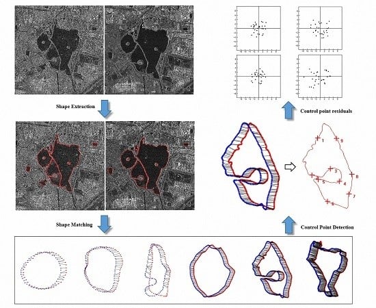
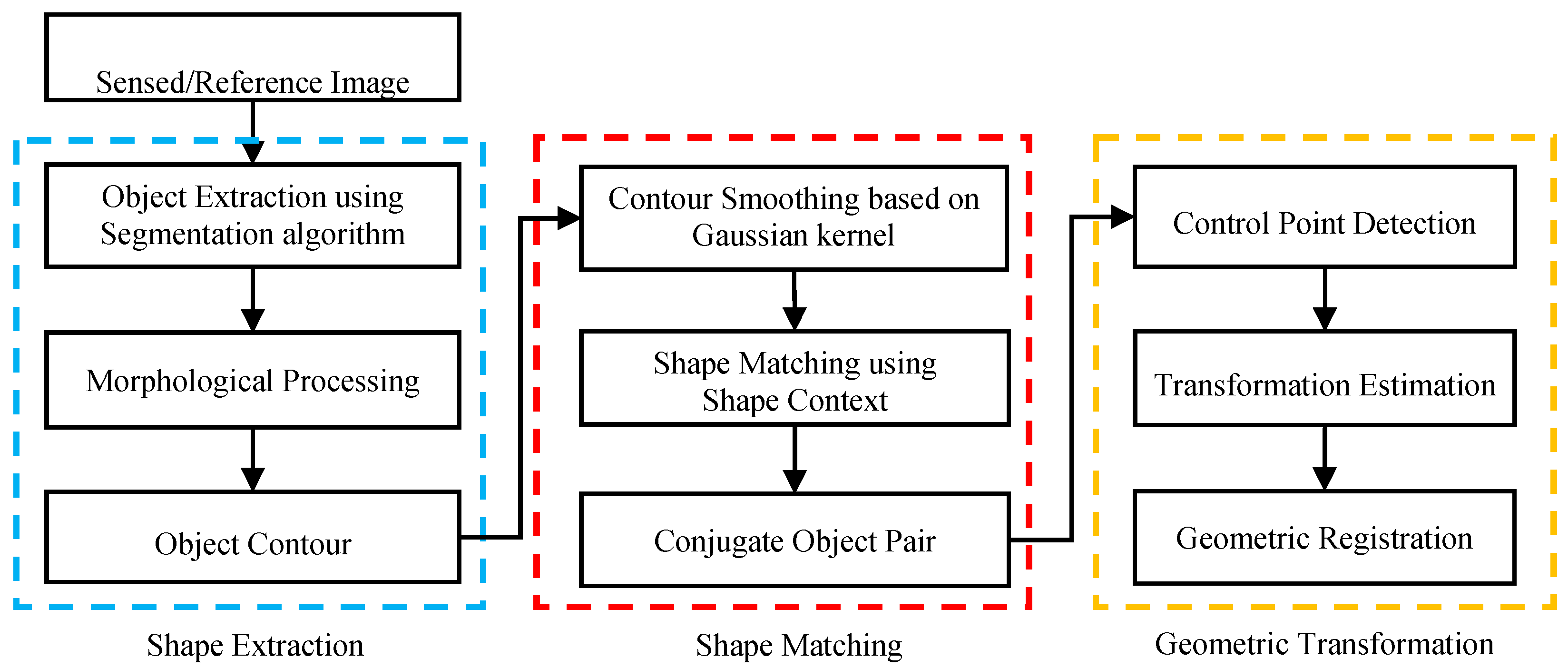
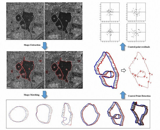
2.1.2. Registration Process

The proposed method is divided into three steps.
(1) Shape extraction. First, distinct ground objects (e.g., lake, vegetation) are extracted from reference and sensed images. Applicable segmentation algorithms and parameters should be used for these different objects respectively. Morphological processing and data vectorization will be used to obtain the contours of the objects (shapes).
(2) Shape matching. Shape processing is essential for shape matching, and contour smoothing can reduce the differences between the shapes of an object in different images. Then, the object shapes in two datasets are compared one by one based on the shape context descriptor. The two shapes that are matched successfully are conjugate object pairs.
(3) Geometric transformation. Control points are detected from unchanged segments on the contours of conjugate object pairs, and transformation estimation is performed using the least squares technique. The two images are geometrically registered based on the transformation parameters.
The flowchart of the proposed method is presented in Figure 1.

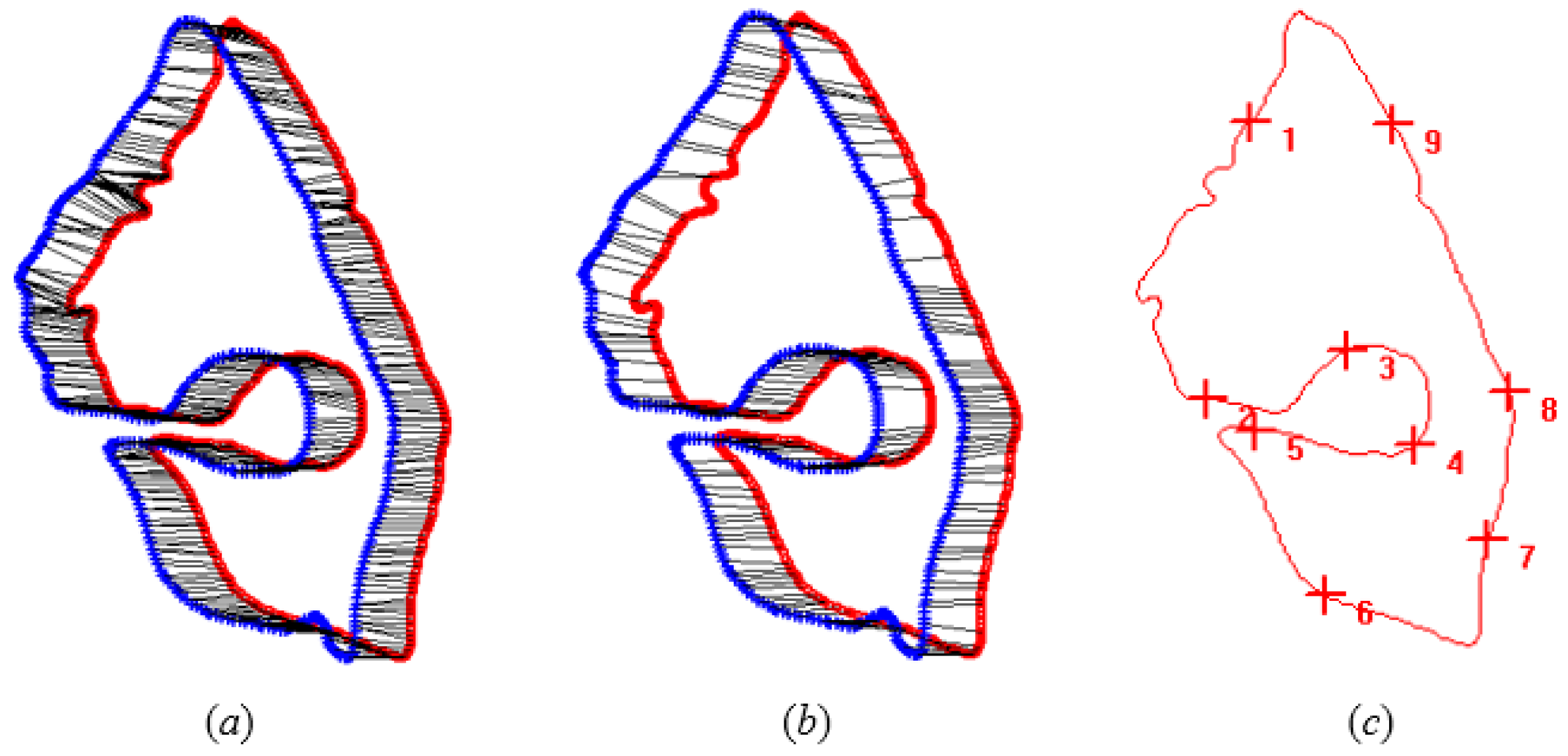
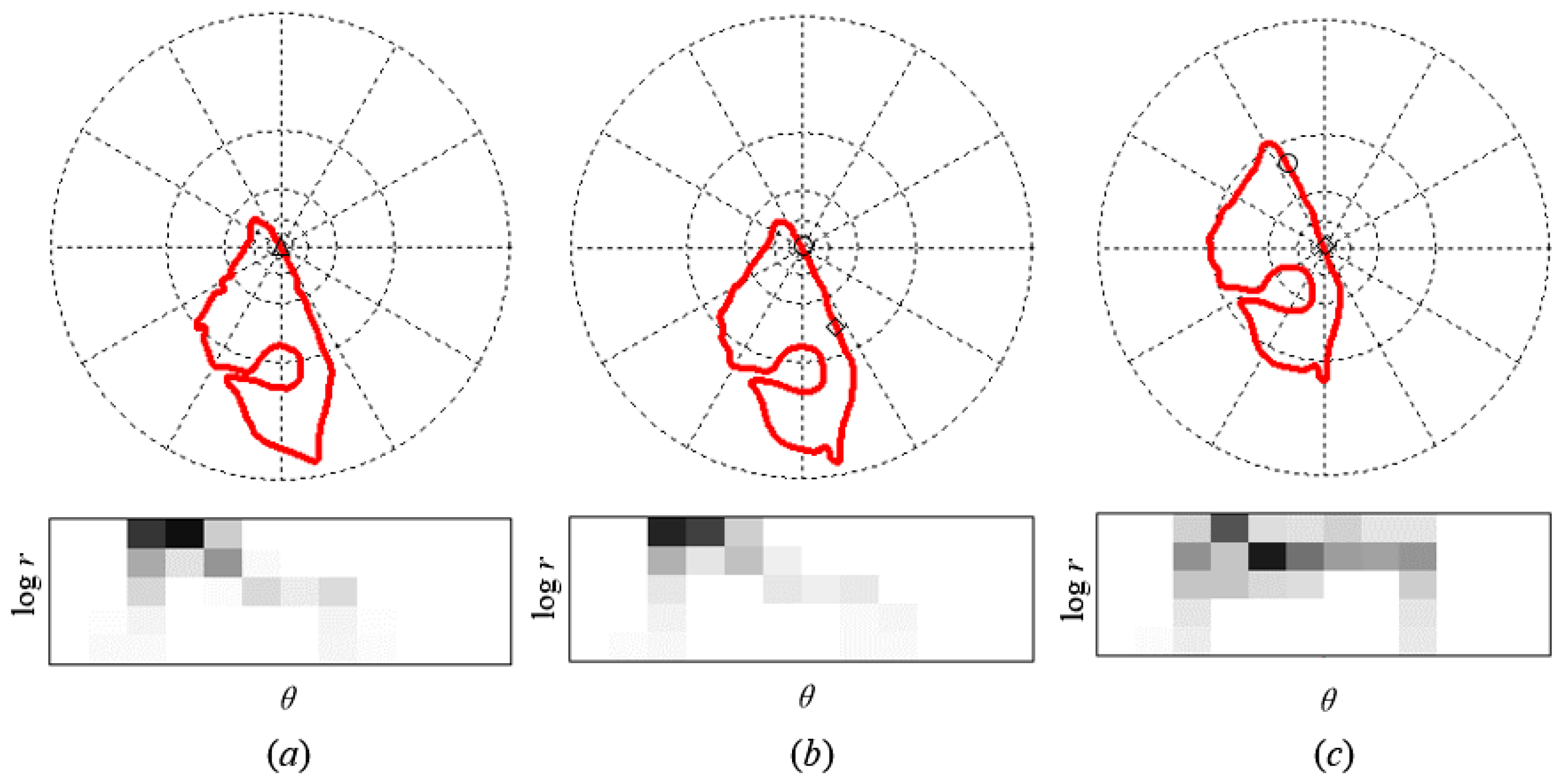
2.2. Shape Matching Using Shape Context

Shape is an important visual feature of an object, which provides the easiest and most obvious recognition information. However, shape matching is still a challenging task, especially for objects in sensed images, which often have complex irregular shapes. The key strategy is to develop an appropriate descriptor to characterize the object’s shape and tolerate local deformations simultaneously. Therefore, a robust matching method for varying the shape of objects in remote sensing images is required.
The original contours are rough and contain small-scale variations due to image differences and segmentation technology. Thus, contour smoothing is essential to reduce these variations and details, i.e., to reduce the differences between object shapes, which is useful for shape matching. In this study, a Gaussian filter was applied to the shape contour. The filter is given by
{ G ( x , σ ) = 1 σ 2 π e x 2 / 2 σ 2 G ( y , σ ) = 1 σ 2 π e y 2 / 2 σ 2
where, ( x ,   y ) are the coordinates of the contour and σ is the kernel width parameter. For the images used in this study, slight smoothing ( σ = 3 ) was appropriate.
The Gaussian filter can effectively protect the extremes from being removed during the process of moving from a coarse to fine scale [14], as shown in Figure 2.
Numerous shape representations and analysis methods based on contour information have been proposed. The most suitable tool for contours is the shape context [15,16]. The shape context at a reference point characterizes the distribution of all other points relative to it, thereby generating a globally discriminative characterization. The shape context uses a log-polar histogram of coordinates and is tolerant of local deformations. The shape context can be used to quickly perform a search for similar shapes via recognition.
For a point p i on the shape, a histogram h i of the relative coordinates of the other n 1 points is defined as follows.
h i ( k ) = # { q p i   : ( q p i ) bin ( k ) }
where #{.} is the statistic of the set of points, k { 1 ,   2 , , K } and K is the number of histogram bins. Five bins are suitable for the polar radius, and 12 bins are suitable for the polar angle [15]. The expression ( q p i ) bin ( k ) indicates that the vector originating from p i to another point, q , belongs to the k th bin.
Note the visual similarities among the shape contexts shown in Figure 3. Corresponding points between two similar shapes share analogous shape contexts, providing a solution for the optimal assignment problem. This method can also be used to measure shape similarity.
The shape context descriptor is based on the characteristics of the histogram, and the χ2 test statistics are used to measure the difference between two points. Consider a point p i on shape A and a point q j on shape B. The cost of matching the two points is defined as follows.
C ij = C ( p i , q j ) = 1 2 [ h i ( k ) h j ( k ) ] 2 h i ( k ) + h j ( k )
where h i ( k ) and h j ( k ) denote the K -bin normalized histograms at p i and q j , respectively.
For the p i of shape A, the matched point in shape B is determined by traversing all of the points of shape B, computing the point-to-point costs, and selecting the point with the minimum cost value (which is less than the threshold). Similarly, we can obtain the matched point of q j in shape A. Two points are called a best point pair if they correspond to one another. The matched point and the best point pair are defined in Equation (4). An example is shown in Figure 4a, b.
MP i j   :   j = arg min   j B   C ij MP j i   :   i = arg min   i A   C ij   BP i j   :   MP i j and MP j i
where MP i j is a matched point pair and indicates that the matched point of p i is q j ; MP j i indicates that the matched point of q j is p i ; and BP i j is a best point pair.
Shape matching aims to find the conjugate object pairs from two datasets. The shape context descriptor can be used to find the matched points between two similar shapes. The percentage of the number of matched points can reflect the shape difference; consequently, a simple similarity measure between two contours was used in this study:
S AB = Total ( MP ) Total ( A )
where S AB is the shape similarity between shapes A and B, Total ( MP ) is the total number of matched points, and Total ( A ) is the total number of points of shape A.
Undoubtedly, control points are located in unchanged segments of two conjugate contours. All of the best point pairs can be deemed to be CP candidates, and several points selected from these point pairs are sufficient for transformation estimation. It should be noted that the CPs remain separated from one another and their distributions should be as even as possible, as shown in Figure 4c.

3. Experiment Results

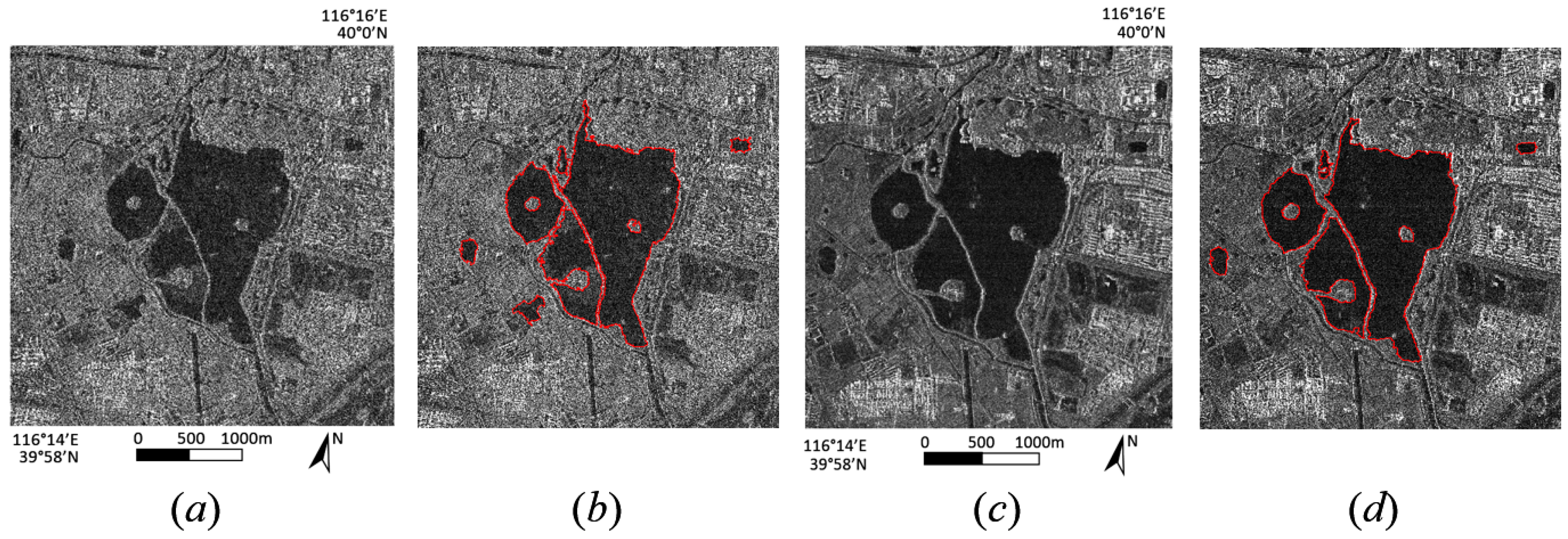
3.1. Data Introduction

Two SAR images of Beijing, China, are chosen for the evaluation of the proposed method. The Radarsat-2 image was acquired on 22 October 2008, and is shown in Figure 5a. The spatial resolution of the image is 1.5 meters per pixel. The TerraSAR-X image was acquired on 22 April 2011, and is shown in Figure 5c. The spatial resolution is 1.25 meters per pixel. The grey differences between the two images are significant, and the features at the conjugate positions are obviously inconsistent, indicating that the registration will be a challenge.

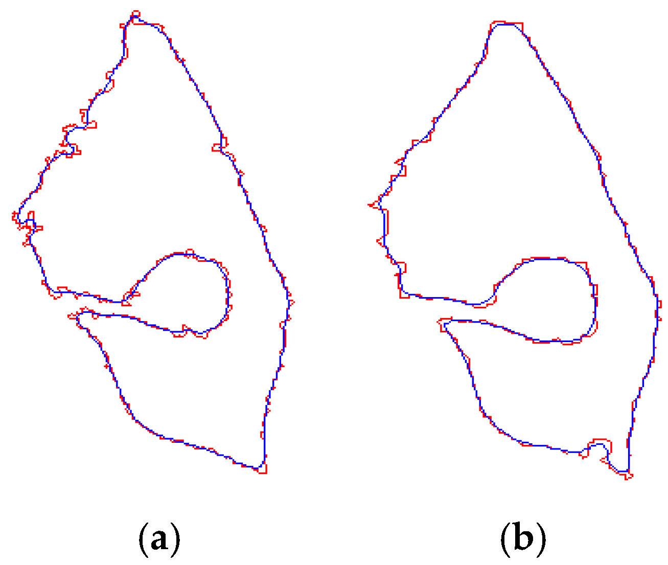
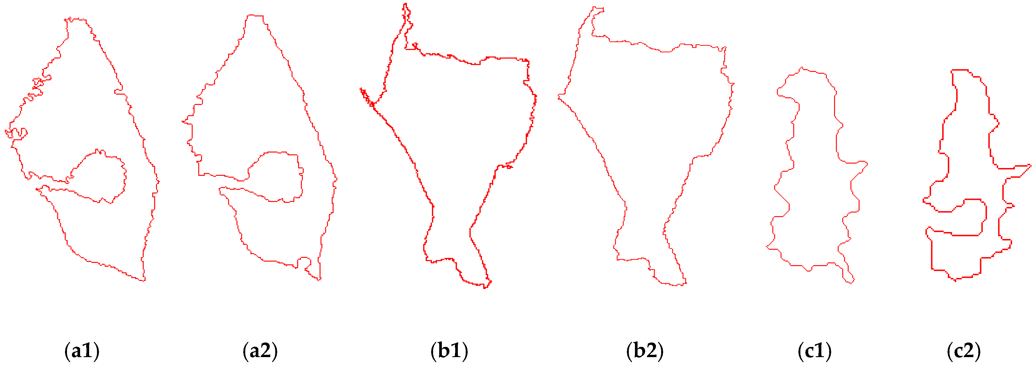
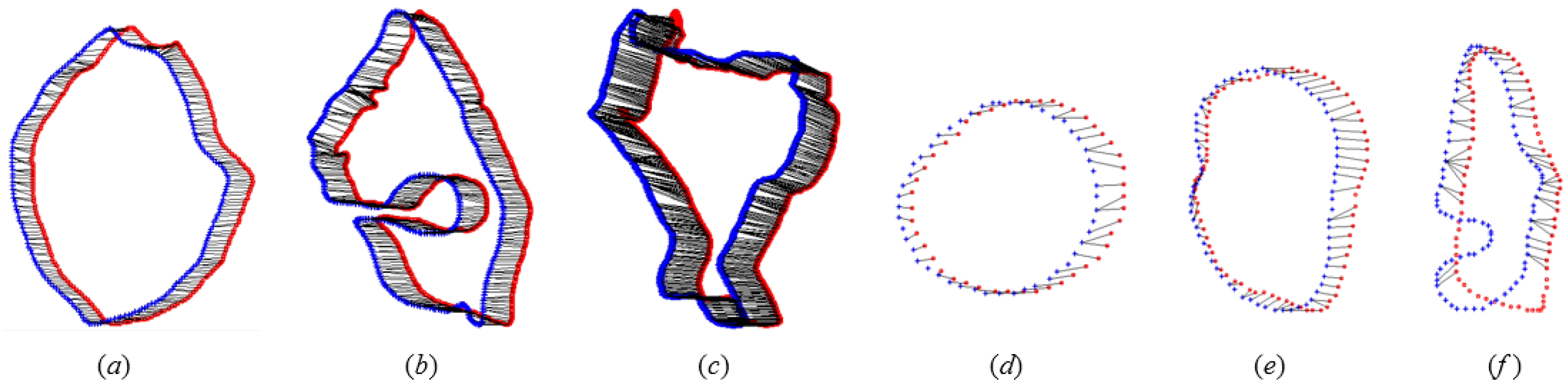
3.2. Shape Extraction and Shape Matching

In this experiment, we select only the water body as the matching object because there are few consistent distinct objects in the urban area. In SAR images, water surfaces behave as spectrum reflectors at radar wavelengths and thus appear as low intensity areas in contrast to brighter regions, such as the rough surrounding terrain, which has diffuse scattering properties. The proposed method based on shape context uses a log-polar histogram of coordinates and is tolerant of local deformations. The shape detail of the object contour is not the key factor for matching. Shape extraction is not the emphasis of this research, therefore image segmentation based on intensity and texture will be used. For the extraction of smooth water bodies, amplitude thresholding approaches are commonly applied. The local mean and variance can be used to distinguish between water and land.
After image segmentation, the filling of holes, the removal of small objects and contour vectorization are necessary to get applicable object shapes. In these procedures, appropriate morphological processing (e.g., erosion, dilation, opening, closing, and boundary) will be used. The contours extracted from the images are shown in Figure 5b,d. The contours in different images are not completely coincidental and have local differences for various reasons, e.g., imaging conditions, object changes, occlusion, and segmentation technology. The example can be shown in Figure 6.
In this study, we focus on the correspondence problem between two incomplete contours of the same object in different images, meanwhile, we detect stable and invariant CPs. Firstly, contour smoothing is essential before shape matching. The contour smoothing can reduce the variations and details. Because contour smoothing is not a key process for shape matching, a slight smoothing is appropriate and excessive smoothing is avoided. The example of smoothing is shown in Figure 2. Secondly, the shape context descriptor is used in shape matching to overcome the correspondence problem. This descriptor exhibits globally discriminative characterization and local deformation tolerance for varying contours. Shape context matching results are shown in Figure 7. Some object contours have relatively large differences, as shown in Figure 7f. It can be seen that the shape detail of the contour is not the key factor for matching.
In previous publications, shape similarity calculations faced heavy computational burdens, and the thresholds of similarity were difficult to determine. In this study, the similarity between two contours is determined by the percentage of the number of matched points. Two contours can be deemed similar if most points in two contours are matched; the threshold (0.5 to 0.8) is suitable in most cases. The proposed similarity measurement is relatively simple in terms of computation and threshold setting.

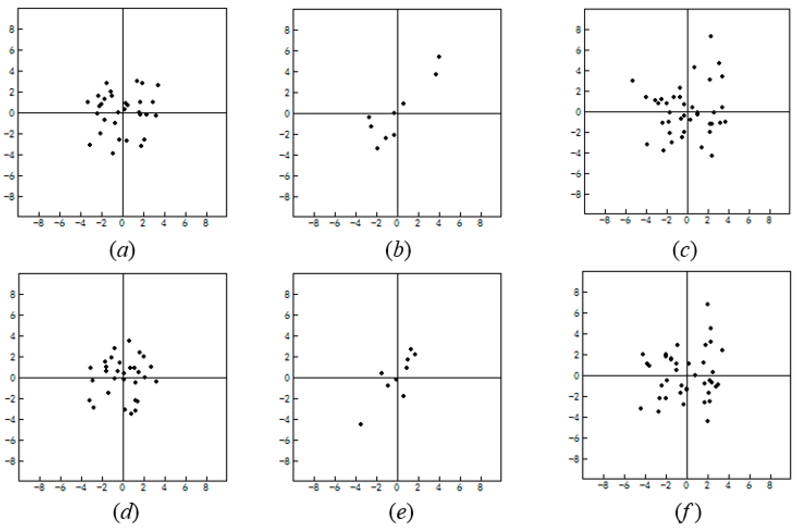
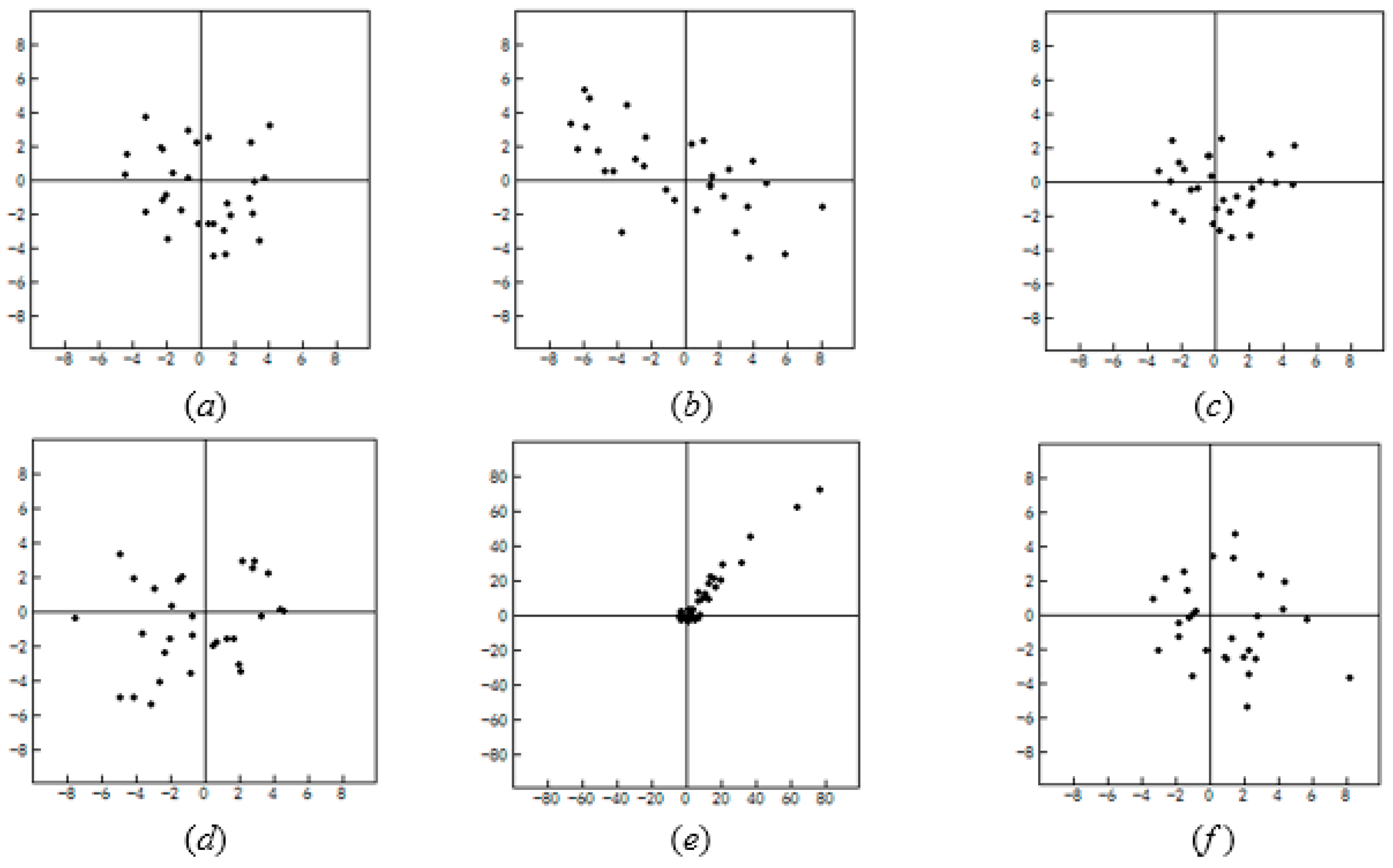
3.3. Geometric Transformation and Registration Result

Control point candidates are selected from the best point pairs of matched contours and should be distributed as uniformly as possible on the contours. The number of CPs is determined by the number of points (or length) of the contour. In our experiments, it is appropriate to select one CP for approximately every 160 to 200 points.
A polynomial model can be used to model the transformation between two SAR images. The first- and second-order polynomial models are the most commonly applied models. These two models were tested in the experiment, and a comparison is shown in Table 1 and Table 2. The results show that the two models are appropriate for image registration in flat urban areas. The first-order polynomial model (i.e., affine transformation) exhibited a slightly higher precision than the second-order model.
The evaluation of the precision of the image registration involves two aspects: an evaluation of the CPs and an evaluation of the check points. All of the CPs can also be considered to be check points by calculating the residuals using the transformation parameters that are based on these CPs. The residual of the CP is the difference (error) between the reference coordinate (in reference image) and the transformed coordinate from the matching image. The evaluation of the CPs not only detects the precision of the CPs and outliers but also indicates whether the current transformation model is suitable or not. The precision statistics of the CPs are shown in Table 1. The CP residuals based on different methods and different models are shown in Figure 8. In general, the magnitude and distribution of CPs residual can be thought of as an indicator of outliers or bias. It can be seen that all of the residuals based on shape context (SC) are congregated and have a good distribution with no bias.
We manually extracted 30 control points from the pairs of images. These points were regarded as check points to evaluate registration precision. The precision statistics of the check points are shown in Table 2. The check point residuals are shown in Figure 9.
The precision criteria include three indexes: root-mean-square error (RMSE), standard deviation (SD), and max error. Every index was computed in three coordinate directions: horizontal, vertical, and integral.
The experimental results show that the proposed method based on shape context (SC) achieves high registration precision. We compare these results with the results obtained using a SIFT-based method. The SIFT descriptor is affected by significant grey differences, and many outliers exist in feature matches. For this image pair, the number of matches based on SIFT is 19, of which 10 point pairs are mismatched. The mismatch ratio can be reduced by adjusting parameters or applying constraints, however, the number of correct matches may be decreased simultaneously. More importantly, the number of correct matches is usually low and the accuracy of CPs is not high, which is not sufficient to achieve high registration precision. This was concluded from Table 1, Table 2 and Figure 7, Figure 8. As expected, the method combining SC with SIFT exhibited slightly better check point precision than SC (see results in Table 2). This is because SIFT CPs may expand the control range and improve the accuracy.

4. Conclusions

This paper presents a novel multi-sensor SAR image registration method based on the object shape. Compared with traditional feature-based methods, the main advantages of the proposed method are that objects can be matched based on shape information and reliable CPs can be detected from unchanged contours, without the correspondence problem mentioned previously. This method is able to sufficiently select many high-quality CP candidates to achieve high registration precision. The shape context descriptor is used for shape matching between objects with local deformations and exhibits globally discriminative characterization for various objects. Traditional edge- or contour-based methods may heavily rely on the initial segmentation result. In contrast, the proposed method is barely affected by grey differences and segmentation results. Local differences can be easily detected and excluded. The proposed method can also be used for SAR and optical images or even images and maps. The major limitation of the algorithm is that it is suitable to distinct ground objects, but there are few distinct ground objects in some areas. Extending this method to general objects will be the goal of our future work.

Acknowledgments

This work was supported by the National Natural Science Foundation of China (Nos. 41331176, 41271425, 41371413) and National Key Research and Development Program of China (2016YFB0501501).

Author Contributions

Jie Rui conceived and performed the experiments; Chao Wang and Hong Zhang supervised and designed the research and contributed to the article’s organization; Fei Jin carried on the comparative analysis. Jie Rui and Hong Zhang drafted the manuscript, which was revised by all authors. All authors read and approved the final manuscript.

Conflicts of Interest

The authors declare no conflict of interest.

References

  1. Zitova, B.; Flusser, J. Image registration methods: A survey. Image Vis. Comput. 2003, 21, 977–1000. [Google Scholar] [CrossRef]
  2. Dawn, S.; Saxena, V.; Sharma, B. Remote sensing image registration techniques: A survey. In Proceedings of 4th International Conference on Image and Signal Processing (ICISP), Trois-Rivières, QC, Canada, 30 June–2 July 2010; Volume 6134, pp. 103–112.
  3. Gong, M.; Zhao, S.; Jiao, L.; Tian, D.; Wang, S. A novel coarse-to-fine scheme for automatic image registration based on SIFT and mutual information. IEEE Trans. Geosci. Remote Sens. 2014, 52, 4328–4338. [Google Scholar] [CrossRef]
  4. Chen, T.; Chen, L. A union matching method for SAR images based on SIFT and edge strength. IEEE J. Sel. Top. Appl. Earth Obs. Remote Sens. 2014, 7, 1–10. [Google Scholar]
  5. Zhu, H.; Ma, W.; Hou, B.; Jiao, L. SAR image registration based on multifeature detection and arborescence network matching. IEEE Geosci. Remote Sens. 2016, 13, 706–710. [Google Scholar] [CrossRef]
  6. Liang, J.; Liu, X.; Huang, K.; Li, X.; Wang, D.; Wang, X. Automatic registration of multisensor images using an integrated spatial and mutual information (SMI) metric. IEEE Trans. Geosci. Remote Sens. 2014, 52, 603–615. [Google Scholar] [CrossRef]
  7. Liu, F.; Bi, F.; Chen, L.; Shi, H.; Liu, W. Feature-Area optimization: A novel SAR image registration method. IEEE Geosci. Remote Sens. 2016, 13, 242–246. [Google Scholar] [CrossRef]
  8. Wang, B.; Zhang, J.; Lu, L.; Huang, G.; Zhao, Z. A uniform SIFT-like algorithm for SAR image registration. IEEE Geosci. Remote Sens. 2015, 12, 1426–1430. [Google Scholar] [CrossRef]
  9. Dellinger, F.; Delon, J.; Gousseau, Y.; Michel, J.; Tupin, F. SAR-SIFT: A SIFT-like algorithm for SAR images. IEEE Trans. Geosci. Remote Sens. 2015, 53, 453–466. [Google Scholar] [CrossRef] [Green Version]
  10. Zhang, H.; Ni, W.; Yan, W.; Wu, J.; Li, S. Robust SAR image registration based on edge matching and refined coherent point drift. IEEE Geosci. Remote Sens. 2015, 12, 1–5. [Google Scholar] [CrossRef]
  11. Li, H.; Manjunath, B.S.; Mitra, S.K. A contour-based approach to multisensor image registration. IEEE Trans. Image Process. 1995, 4, 320–334. [Google Scholar] [CrossRef]
  12. Eugenio, F.; Marques, F. Automatic satellite image georeferencing using a contour-matching approach. IEEE Trans. Geosci. Remote Sens. 2003, 41, 2869–2880. [Google Scholar] [CrossRef]
  13. Pan, C.; Zhang, Z.; Yan, H.; Wu, G.; Ma, S. Multisource data registration based on NURBS description of contours. Int. J. Remote Sens. 2008, 29, 569–591. [Google Scholar] [CrossRef]
  14. Babaud, J.; Witkin, A.P.; Baudin, M.; Duda, R.O. Uniqueness of the Gaussian kernel for scale-space filtering. IEEE Trans. Pattern Anal. Mach. Intell. 1986, 1, 26–33. [Google Scholar] [CrossRef]
  15. Belongie, S.; Malik, J.; Puzicha, J. Shape matching and object recognition using shape contexts. IEEE Trans. Pattern Anal. Mach. Intell. 2002, 24, 509–522. [Google Scholar] [CrossRef]
  16. Huang, L.; Li, Z.; Zhang, R. SAR and optical images registration using shape context. In Proceedings of the IEEE International Geoscience and Remote Sensing Symposium (IGARSS2010), Honolulu, HI, USA, 25–30 July 2010; pp. 1007–1010.
Figure 1. Image registration flowchart.
Remotesensing 08 00923 g001
Figure 2. Curve smoothing for two different shapes. (a) Shape A, (b) Shape B. The red line is the original contour, and the blue line is the Gaussian smoothing result.
Remotesensing 08 00923 g002
Figure 3. Sampled edge points of two shapes and example histograms of the shape contexts. (a) Example shape context for shape A is marked by△. Example (b) and (c) shape contexts for shape B are marked by ○ and ◇. Each shape context is a log-polar histogram of the coordinates of the rest of the point set, measured using the reference point as the origin. (Dark = large value). Note the visual similarities of the shape contexts for △ and ○, which were computed for relatively similar points on the two shapes. However, the shape context for ◇ is quite different.
Remotesensing 08 00923 g003
Figure 4. Shape context matching and control point (CP) selection: (a) the matching point from shape A to shape B; (b) correspondences between the best match pairs, wherein the costs are minimal for the two shapes; (c) CPs selected and uniformly distributed on the best match pairs.
Remotesensing 08 00923 g004
Figure 5. (ad) SAR images and extracted contours: (a) Radarsat-2 image, (c) TerraSAR-X image; (b) and (d) are extracted contours of (a) and (c).
Remotesensing 08 00923 g005
Figure 6. The example for incomplete contours of the same object in different images. (a1) and (a2), (b1) and (b2), (c1) and (c2) are three contour pairs extracted from different images respectively.
Remotesensing 08 00923 g006
Figure 7. Shape context matching: (af) are six shape pairs with matching results.
Remotesensing 08 00923 g007
Figure 8. (af) Control point residuals. The first and second rows correspond to 1st-order and 2nd-order polynomial models, respectively. Left (a) and (d) SC, middle (b) and (e) SIFT, right (c) and (f) SC+SIFT.
Remotesensing 08 00923 g008
Figure 9. Check point residuals. The first and second rows correspond to 1st-order and 2nd-order polynomial models, respectively. Left (a) and (d) SC, middle (b) and (e) SIFT, right (c) and (f) SC+SIFT.
Remotesensing 08 00923 g009
Table 1. Quantitative Results of Control Points.
MethodNumber of CPsPolynomial ModelRMSEStandard DeviationMax Error
xyxyxyxyxyxy
SC311st-order1.921.882.691.921.881.063.46−3.974.39
2nd-order1.721.832.511.721.831.013.21−3.574.07
SIFT91st-order2.332.733.592.332.731.884.085.346.72
2nd-order1.572.112.631.572.111.48−3.45−4.605.75
SC+SIFT401st-order2.342.433.372.342.431.59−5.287.237.61
2nd-order2.222.313.212.222.311.33−4.356.747.05
Table 2. Quantitative Results of Check Points.
MethodNumber of Check PointsPolynomial ModelRMSEStandard DeviationMax Error
xyxyxyxyxyxy
SC301st-order2.452.333.382.452.271.10−4.36−4.445.16
2nd-order3.002.433.862.982.341.50−7.34−4.987.35
SIFT1st-order4.052.514.764.022.482.148.195.228.35
2nd-order22.5222.3131.7018.1618.5924.7177.4171.16105.15
SC+SIFT1st-order2.27 1.672.822.25 1.611.074.74 −3.315.16
2nd-order2.85 2.453.762.65 2.391.638.26 −5.419.06

