Article

A Virtual Restoration Approach for Ancient Plank Road Using Mechanical Analysis with Precision 3D Data of Heritage Site

1
Architecture Department, Chang’an University, No. 161, Chang’an Road, Xi’an 710061, China
2
Architecture Department, Xi’an University of Architecture & Technology, No. 13, Yanta Road, Xi’an 710055, China
3
School of Remote Sensing and Information Engineering, Wuhan University, No. 129, Luoyu Road, Wuhan 430079, China
4
School of Internation Software, Wuhan University, No. 129, Luoyu Road, Wuhan 430079, China
5
Shaanxi Bureau of Cultural Heritage, No. 193, Yanta West Road, Xi’an 710061, China
*
Authors to whom correspondence should be addressed.
Remote Sens. 2016, 8(10), 828; https://doi.org/10.3390/rs8100828
Submission received: 6 August 2016 / Revised: 19 September 2016 / Accepted: 27 September 2016 / Published: 9 October 2016
(This article belongs to the Special Issue Remote Sensing for Cultural Heritage)

Abstract

:
The ancient plank road is a creative building in the history of Chinese ancient traffic through cliffs. In this paper, a virtual restoration approach for ancient plank road using mechanical analysis with precision 3D data of current heritage site is proposed. Firstly, an aero photogrammetry with multiple view images from Unmanned Aerial Vehicle (UAV) imaging system is presented to obtain the 3D point cloud of ancient plank roads, which adopts a density image matching and aerial triangulation processing. In addition, a terrestrial laser scanner is integrated to obtain detail 3D data of the plank road. Secondly, a mechanical analysis method based on the precision 3D data of the current plank roads is proposed to determine their forms and restore each of their components with detail sizes. Finally, all components and background scene were added to the existing model to obtain a virtual restoration model, which indicates that it is effective and feasible to achieve a three-dimensional digital and virtual restoration of ancient sites. The Chiya Plank Road is taken as a virtual restoration example with the proposed approach. The restored 3D model of the ancient plank can be widely used for digital management, research, and visualization of ancient plank roads.

Graphical Abstract

1. Introduction

Plank road refers to the path in the cliffs of the dangerous places along the river, which can allow for marching, transport of food baggage and caravan business traffic to reduce travel time. The ancient plank road is a creative building in the history of Chinese ancient traffic. The ancient plank roads were easily ruined because a large number of wood materials were adopted to build the ancient plank roads such as the pillars and pavement [1,2,3]. In addition, the harsh natural environment of the plank roads in the cliffs led to the vanishing of ancient plank road. How to restore ancient plank roads becomes a big challenge for the protection of ancient heritage.
In recent years, there have been increasing cases of rebuilding and exhibition of archaeological sites and cultural relic buildings by three-dimensional modeling. There are many methods for three-dimensional digital modeling; although final models show a similar effect, they are established based on different data sources. The common data are: two-dimensional GIS data [4,5], three-dimensional GIS data [6,7,8], aerophotogrammetric data [9], three-dimensional laser scanning data [10], manually measured data, etc. There are models established based on various already surveyed and mapped data, such as three-dimensional digital modeling data for the ancient architectural structure of the Forbidden City, which are composed of surveying and mapping drawings and two-dimensional images as the main components and scanning point cloud data as the auxiliary component [11]. Three-dimensional modeling for the historic site of Guanggang Works is based on data obtained with the aid of aero photogrammetry by an unmanned aerial vehicle and terrestrial laser scanning [12]. These three-dimensional models established based on data obtained by precision measurements and other surveying and mapping are higher in fidelity and precision.
For the majority of the 3D modeling based on precisely measured data, even though it is used in some areas like archaeology [13,14,15], historic building [16,17], and paleobiology [18], their fundamental objectives are still limited to information preservation and image display, and fail to support the in-depth research of cultural relic restoration. We have to pay more attention to a few examples. Meanwhile, the Direttiva del Presidente del Consiglio dei Ministri (DPCM) procedure is applied to Santa Maria del Mar Church in Spain for seismic vulnerability assessment [19], and the researchers adopt the model generated by three-dimensional scanning data to carry out the virtual restoration of the bob on the Tongnan Buddha in Chongqing [20]. Kontogianni considered that virtual renovation is a combination of different data sources, emphasizing that a temple (sacred place) has been virtually renovated by modeling columns, walls, roofs and pediment [21]. For the Four Dublin Courts’ historic Building Information Model (HBIM), after laser scan survey registration and processing, the model was created for the damaged section of the building and is presented as two separate workflows in this paper [22]. Some researchers use the Kullback–Leibler metric principle of minimum-information-mismatch (MIM) to highlight the most appropriate rule for the classification of a particular object. The experimental study program and results are presented in the automatic gray-scale image recognition problem [23]. In addition, the combined use of photogrammetric techniques and geometrical and numerical strategies to detect the origin of damage and evaluate the current stability [24] is very rigorous. Such cases are infrequent, and the application of such virtual technology to the restoration and protection of cultural relics still deserves further exploration to a great extent.
The work presented in this paper aims to restore the ancient plank roads with precision 3D data of the existing heritage sites. UAV based aerial photography and photogrammetry processing and TLS are presented for the precision data collection of the existing plank roads together with the surrounding information. These precision 3D data of the existing heritage sites are taken for the mechanical analysis to determine the plank road forms and restore each component with detail sizes of the plank road. Finally, all component and background scene were added to the existing model to obtain a virtual restoration of the ancient plank road. The Chiya Plank Road is taken as a virtual restoration example with the proposed approach. The restored 3D model of the ancient plank can be widely used for digital management, research, and visualization of ancient plank roads.

2. Background

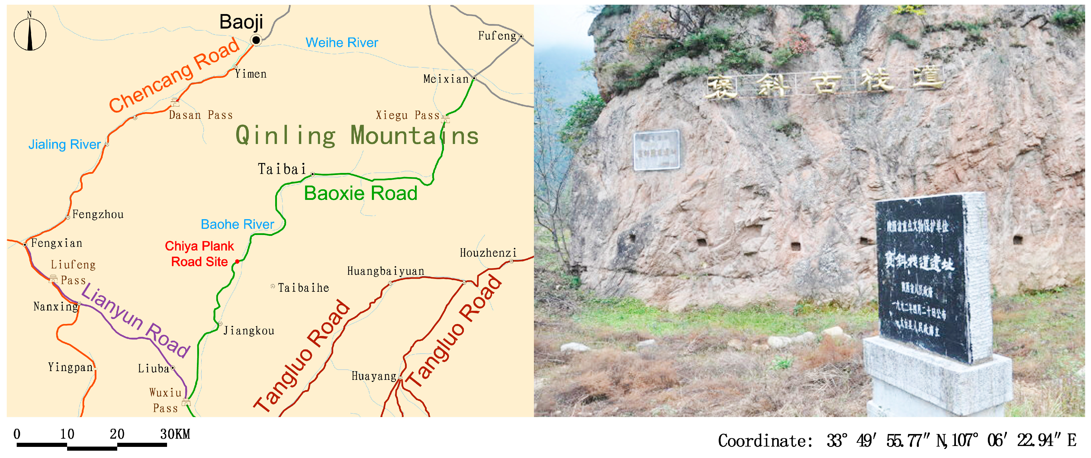
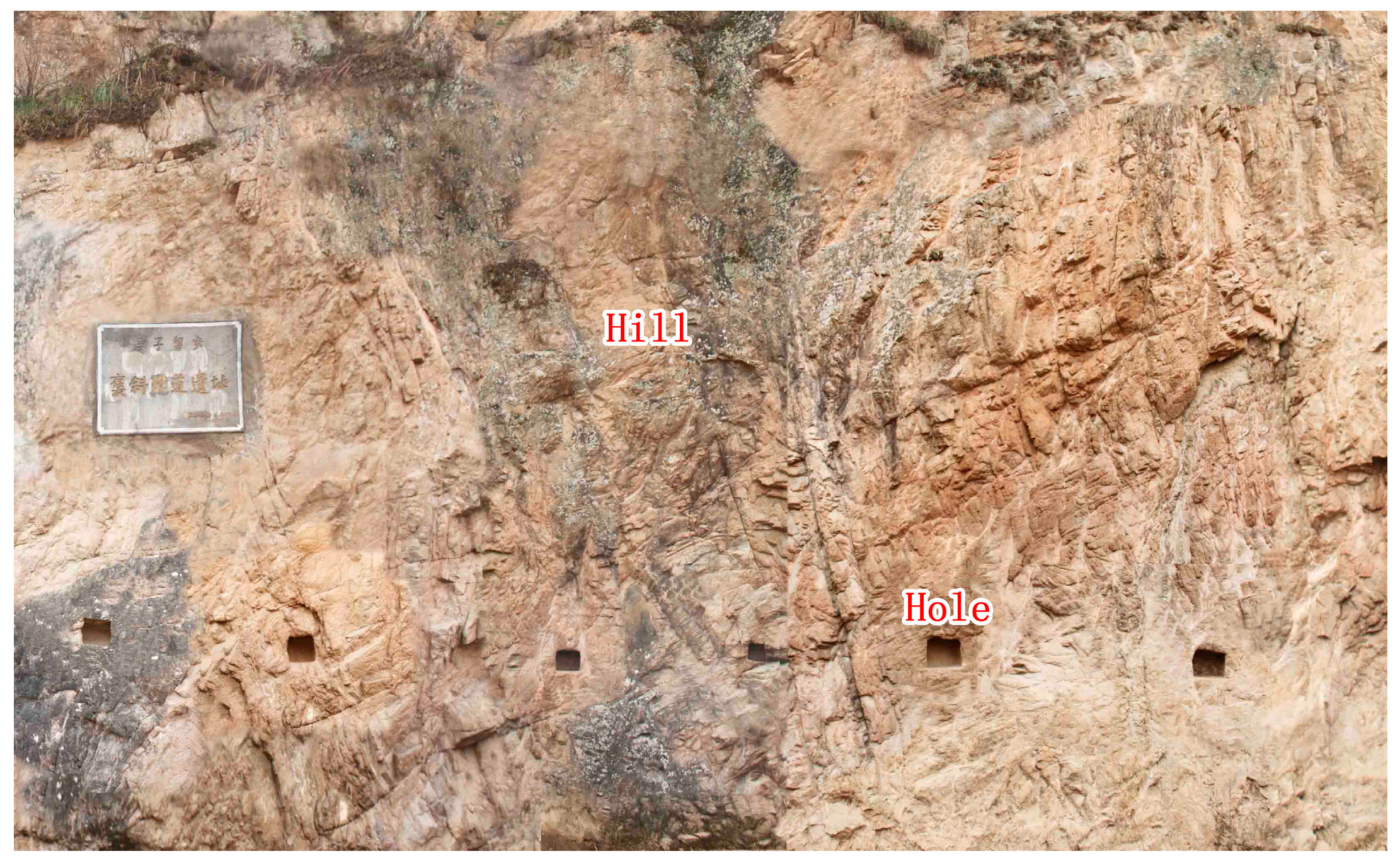
2.1. Study Area: Chiya Plank Road

The Chiya Plank Road was located on the rock wall on the west bank of the Hongyan River Valley, Wangjialeng Town, Taibai County, Baoji City, Shaanxi Province, China. There are 12 square holes for the plank road reserved at the turning and on both sides of the rock wall of the cliff, stretching for 30 m, as shown in Figure 1, with the ancient river course below the plank road. There are no hole relics on the ground due to erosion caused by river water.
The Chiya Plank Road is an early and well-preserved plank road along the line of Shu Road, and has a high value for research; some scholars have conducted a preliminary investigation on it [25].

2.2. Objectives and Research Questions

In order to support application of Shu Road [26,27,28] to be included in the world’s natural and cultural heritages, it is the first time that the Shaanxi Provincial Department of Cultural Relics entrusted the relevant departments and personnel with the virtual restoration of ancient plank roads in many places by precision measurement and three-dimensional modeling software in 2015 in China. This paper will elaborate on the fundamental principles of surveying and mapping as well as the restoration of ancient plank roads and take Chiya Plank Road as an example for analysis. The objective of this paper is to restore the basic geometry features and background scenes of the Chiya Plank Road as it was during the Three Kingdom Period with remnants of ruins reduced as much as possible. The virtual renovation purpose is to restore the historical scenes of heritage sites and show them to the public.
From the site’s current situation, only holes for plank road are saved, as shown in Figure 2, and any the other information of plank road required speculation. There are three main problems to be considered in the restoration: first, how to obtain precise information on the historic site, which needs technology of precision measurement; second, how to infer the form of the plank road and estimate the size of every component of the plank road according to the information on the historic site of the plank road, which needs to read ancient literature and to know mechanical calculation; and, third, how to build a restoration program and show the effects of restoration, which needs the specific modeling software.

3. Methodology

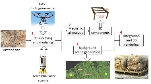
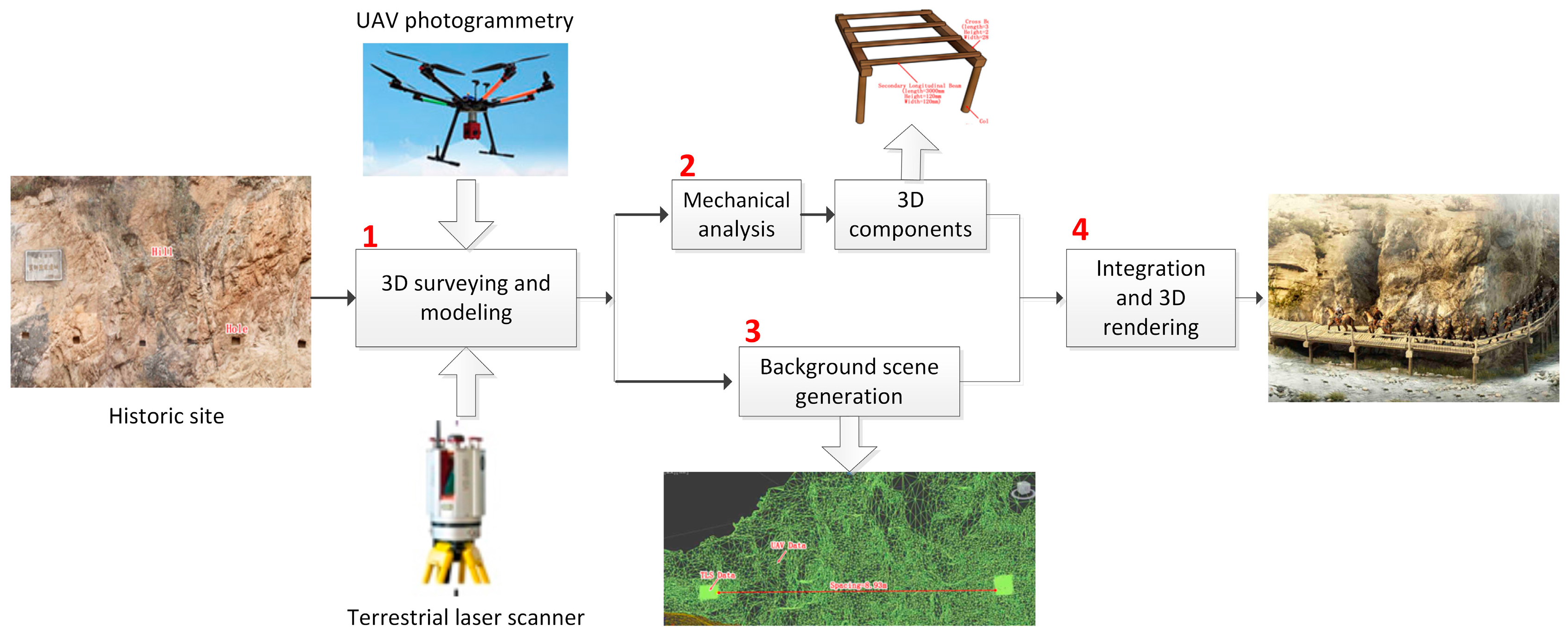
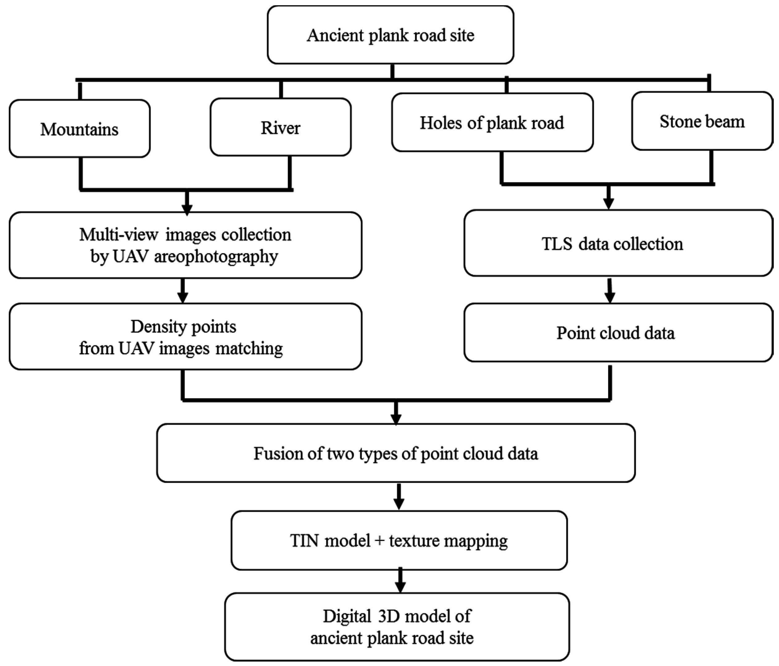
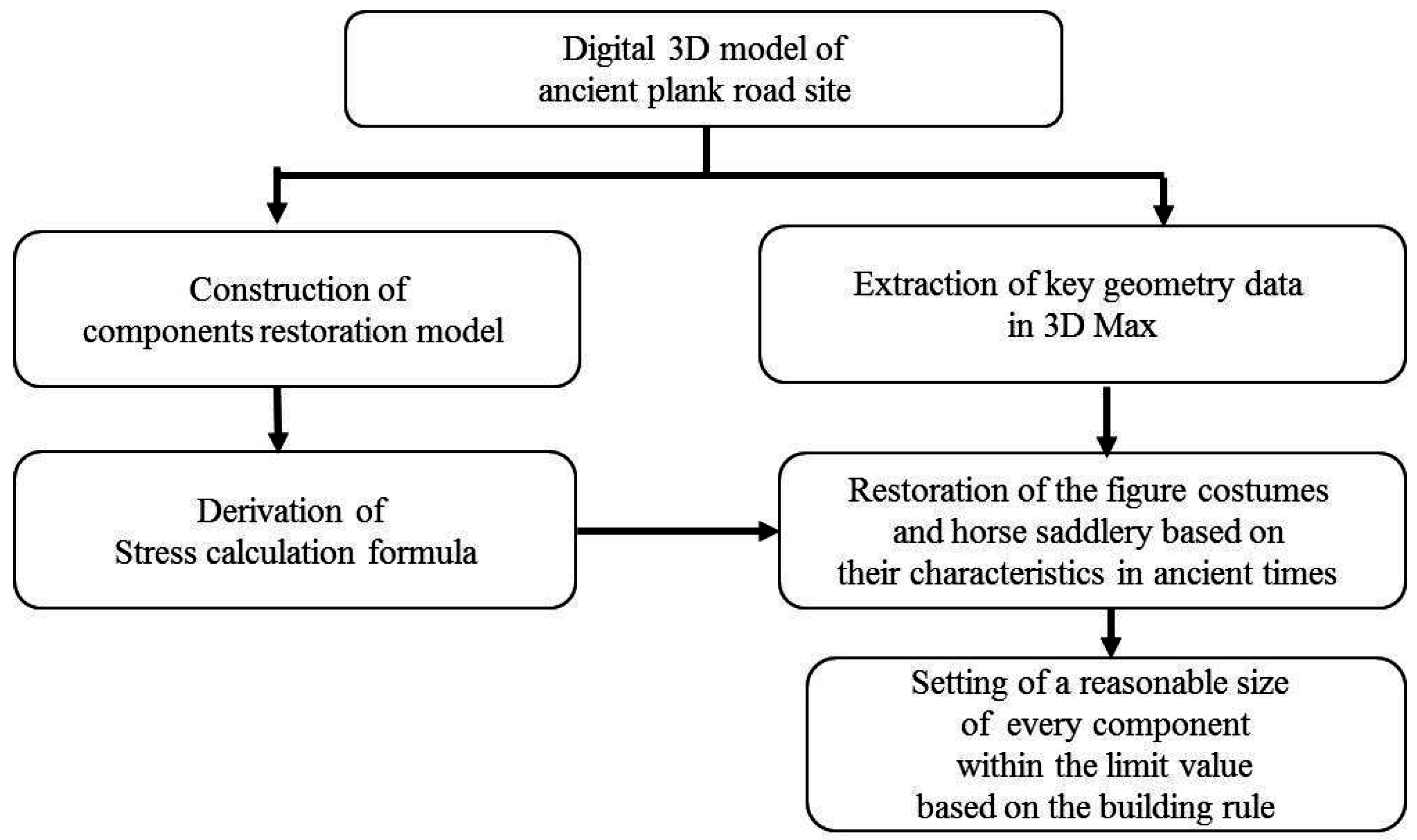
3.1. Technique Flowchart of 3D Restoration Based on Mechanical Analysis

The deep and unique location with wood materials made the ancient plank roads easily ruined. Lack of information is a big challenge for the restoration of the historic road. 3D data of the current remain plank road is adopted to infer the ruined components using the mechanical analysis approach. The proposed ideas are explained in Figure 3.
The proposed approach includes four steps. The first step is to carry out surveying and mapping of the historic site of the plank road to obtain detail 3D data of the existed historic site, which will be introduced in Section 3.2. Then, the 3D data are adopted to generate the background scene, as discussed in Section 3.2.4. The third step is to carry out a structural analysis and make mechanical calculations based on the three-dimensional model for the plank road to restore the 3D components of the plank road site in Section 3.3. Finally, the 3D components and background scene are integrated together to generate a final three-dimensional model of the plank road, which will be introduced in Section 3.3.4. In addition, the 3D rendering is presented for the virtual restoration and representation of the Chiya Plank Road Site, which will be introduced in Section 4.1.

3.2. Precision 3D Surveying Using UAV Photogrammetry and TLS Integration

The majority of ancient plank roads are located on cliffs in valleys, and the first step to build a plank road is to cut holes into the cliff and then insert a wooden or stone cross beam into the hole, on which wood planks with other auxiliary components are paved and installed to form an overhead traffic facility for people to go through. Since the wooden structures have rotted, most of the plank roads have been reduced to residual holes, with stone crossbeams still kept in a few plank roads. Ancient plank roads are composed of four essential elements: a mountain, a river, holes of the plank road (including holes for a cross beam and column) and stone beams, in which a mountain and holes of a plank road are essential, while a river and a stone beam are only seen in historic sites for some plank roads.
Given the poor conditions for surveying and mapping in valleys, various surveying and mapping methods will be adopted for data acquisition in order to ensure the integrity and precision of surveying and mapping, and various data will also be subject to comprehensive application in modeling to ensure high quality of the model [29]. The entire surveying, mapping, and modeling contain four stages (Figure 4): the first stage is to adopt a Unmanned Aerial Vehicle (UAV) to carry out aerial photography to obtain a valley image; the second stage is to adopt three-dimensional laser scanning to obtain rock wall data; the third stage is to make two types of point cloud data subjected to fusion; and the fourth stage is to adopt fused data to generate a triangulation network and carry out texture mapping to generate a three-dimensional digital model.

3.2.1. Mountain and River Data Acquisition Using UAV Photogrammetry

A multi-view UAV is adopted to carry out oblique aero photogrammetry to acquire image data for the mountain and river. Control points for aerial photography are prepared on conspicuous positions with smaller ground height differences along the flight course, with a scan station adopted for coordinate measurement. The aerial images of the Chiya Plank Road are processed by Smart3DCapture Software (V3.2). The system, after auto-match, carries out error compensation settlement based on image control points to output aerial triangulation encryption and then generates DSM (Digital Surface Model) point cloud data by the dense matching of discrete points and acquire DSM point cloud data after the removal of the interference [30,31].
An eight-rotor and five-view-angle UAV was adopted for the surveying and mapping of the Chiya Plank Road, with the following specifications: a Canon 5D MkII side Camera having about 3 cm fixed focal length, the field of view is 122°, flight height is 350 m, and the spatial resolution is 8 cm. The UAV was flown along the canyon from the south to the north, for five missions with a flight distance of about 1 km each ride, and taking 25 to 30 min. The degree of image forward overlap was more than 70%, and the side overlap degree being more than 30%, which helped us to obtain about 3000 effective images. The UAV has a Position and Orientation System (POS), and for this advantage we could get the positioning of the site. The images were subjected to automatic processing by Smart3DCapture for about five days to generate point cloud data.

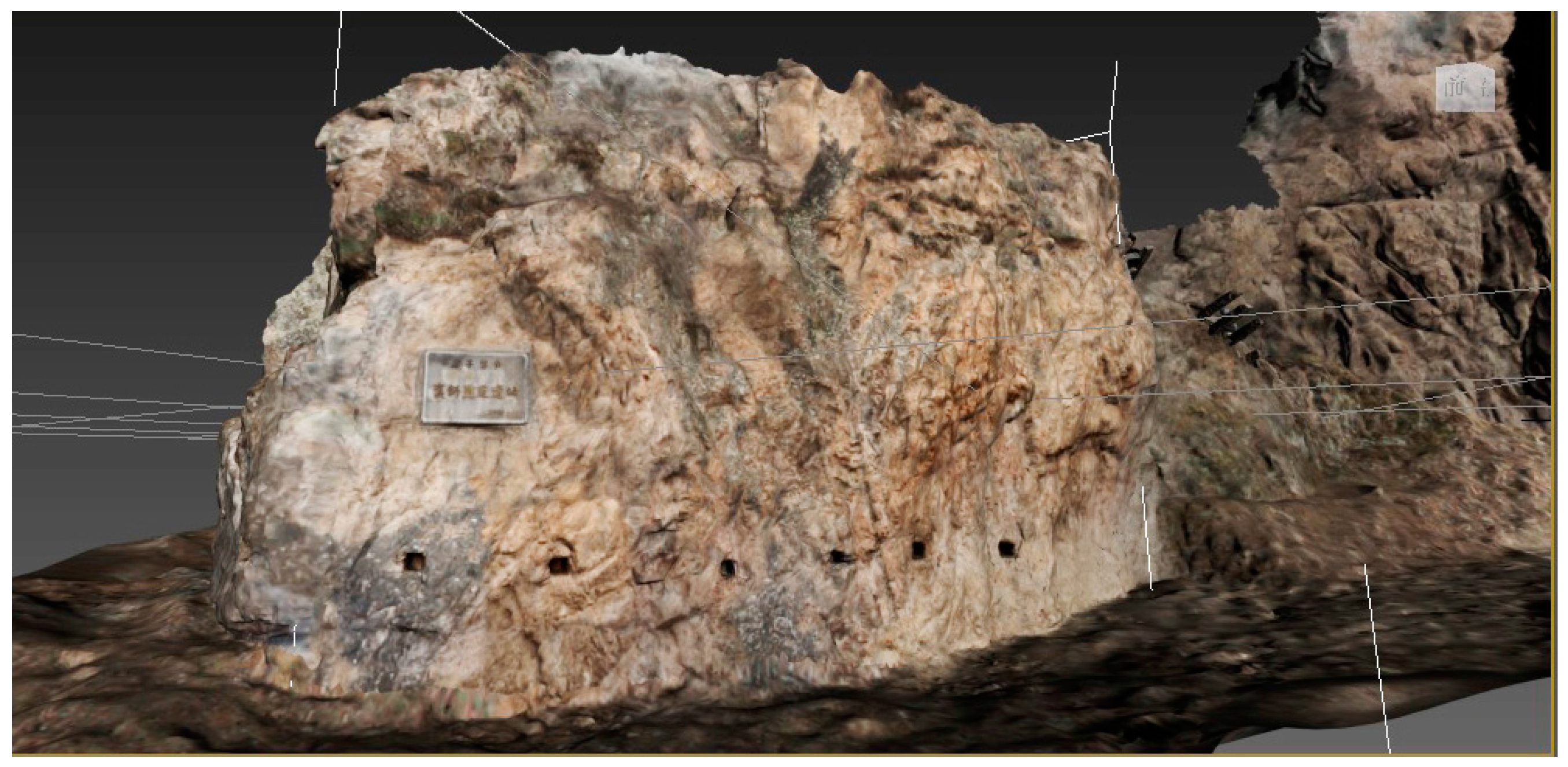
3.2.2. Data Acquisition for Holes and Stone Beams of the Plank Road Using TLS (Terrestrial laser Scanning)
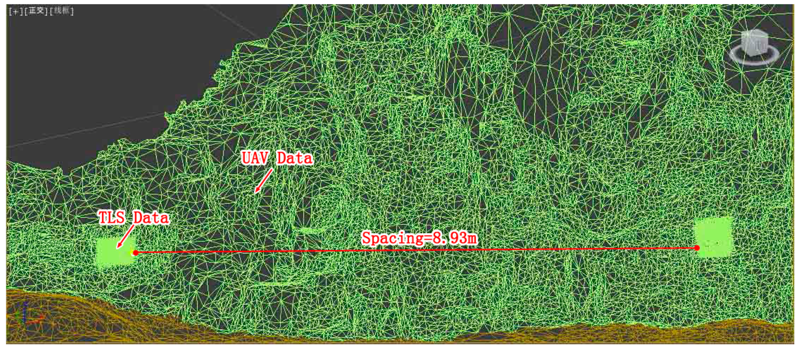
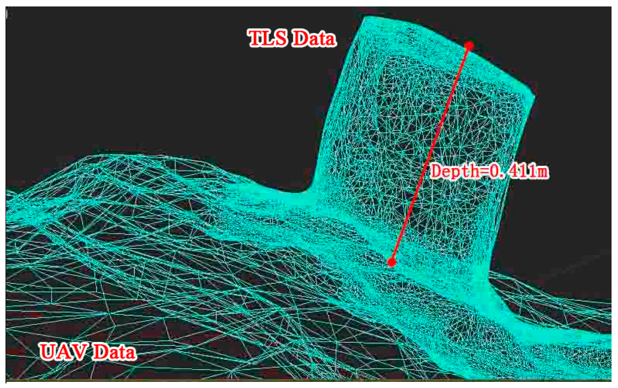
First, the vegetation in holes could be cleaned in order to acquire in-depth data for those holes. A scan station was adopted to carry out three-dimensional scanning of the rock wall where the holes for the plank road are located. Many survey stations were established in positions with relatively high topography under the rock wall on the other side of valley with target points for surveying and mapping set up at four corners in the rock wall under survey at a conspicuous position in the mountain. Data acquired by three-dimensional laser scanning was subjected to processing by software, with splicing and coloring completed to obtain effective point cloud data to achieve fusion with the point cloud data generated by aerial photography with UAV.
A Leica P40 total station was adopted for surveying and mapping, the sampling rate was 1,000,000 points/s, the accuracy of ranging is up to 1.2 mm + 10 ppm, angle measurement accuracy is 8″, six survey stations were set up in positions with relatively high topography 100 m–150 m away from the rock wall, and the scanning density is 2 mm × 2 mm. There are 12 target points, a Leica TC2003 total station was adopted for surveying, the accuracy of ranging is 1 mm + 1 ppm, angle measurement accuracy is 0.5″, data such as the depth of the holes for the plank road were surveyed manually with precision being up to 1 mm, point cloud data acquired by the P40 total station were subjected to automatic processing by Cyclone (Made by Leica Geosystems AG, Heerbrugg, Switzerland) and the duration for data processing was 0.5 h.

3.2.3. Data Fusion

The point data acquired with TLS were filtered for noise cancellation and undesired information removal using the automatic filtering software (Cyclone V7.0, Leica Geosystems AG, Heerbrugg, Switzerland). A target point coordinate was adopted to transfer the entire point cloud to the actual engineering coordinates. At four corners and at the proximity of the Chiya Plank Road site midpoint, four points are chosen from the topocentric ones measured by RTK to convert the accurately spliced point cloud into real coordinate system as a whole. All of the real coordinate-measured topocentric points are used to examine the accuracy of the converted point cloud coordinates. According to the examination results, the plane error is 6.4 cm and elevation error is 7.3 cm. The Terrestrial Laser Scanner (TLS) point cloud data were taken as reference to make the homologous point matching aerial images-generated DTM (Digital Terrain Model) point cloud by the iterative closest point (ICP) algorithm and in order to achieve a fusion of two types of point cloud data.
The RTK surveying of GCPs allowed us to obtain the aerial UAV and paratrike point cloud under the global coordinate system, and this helped us reach a final relative precision of 1 cm. Regarding the TLS, different scans were aligned and then co-registered with the UAV and paratrike photogrammetric point cloud using the matching points which are manually defined as initial approximations. This was performed using each dataset of coordinates in its coordinate system; that is, the local system in case of the aligned TLS point cloud and absolute system for the photogrammetric point cloud, and then the application of the ICP algorithm and Least Squares Matching (LSM) variation [32]. The ICP algorithm requires only a procedure to find the closest point on a geometric entity at a given point. It always converges monotonically to the nearest local minimum of a mean-square metric distance, and the convergence rate is speedy during the first few iterations. It can globally minimize the mean-square metric distance over all six degrees of freedom by testing each initial registration [33]. The Chiya Plank Road point cloud data fusion was done using the manual Cyclone with manual and took 30 min.

3.2.4. Triangulated Irregular Network Model Generation and Texture Mapping

The fused point cloud data are then implemented to generate a triangulated irregular network (TIN) by the incremental insertion method. The Leica P40 total station with a matching CCD Camera could automatically take texture mapping, with the CCD Camera using High-Dynamic Range (HDR) and having a resolution of 80,000,000 pixels. The images acquired by a CCD camera were taken as texture mapping to TIN to obtain a realistic three-dimensional digital model based on the true coordinate system.
In surveying and mapping, the fused point cloud data were translated to TIN by Cyclone with great speed and then the images shot by the Leica P40 total station were processed to be a TIF file by Photoshop as a texture mapped on model by 3Ds Max to generate a three-dimensional model for the existing historic site of the Chiya Plank Road, as shown in Figure 5. Through analyzing the model’s triangulated irregular network (TIN), we could know the size of a network and, then estimate the precision of data. The model for the mountain area based on data surveyed by aerial photography with UAV is within 10 cm in precision and the model for the hole areas based on data obtained by three-dimensional laser scanning is within 0.5 cm in precision. The 3D model is available for surveying and editing in 3Ds Max, having laid a solid foundation for virtual restoration.

3.3. 3D Restoration Based on Mechanical Analysis

The building form of plank roads, as shown in historical documents and ancient paintings, is primarily composed of cross beams and column types, cross beams and column-free types, cross beams and suspension cable types, cross beams and crosswise brace types, or beam columns crosswise brace types, and has various modes for node processing and detailed characteristics [34].
Since many plank road sites have been reduced to residual holes, it is therefore necessary to speculate their form, practice, cantilever length, joint connection, and detail characteristics in a rational manner. The purpose of restoration is to restore ancient plank roads to their original appearance as best as possible based on incomplete information and by way of analysis of their present characteristics in a scientific way.
Attention should be paid to the following points: first, achievement in restoration should be made by fully depending on the digital model generated based on precision surveying and mapping; second, although there was a special practice to build plank roads, they were not built in strict accordance with drawings, which had been slightly adjusted according to the variation in the local landform, and, accordingly, it is unnecessary and impossible to achieve absolutely precise restoration; and, third, plank roads should be simple in form and size to the greatest extent, for example, the guardrail of plank roads shown on ancient paintings is only composed of two crosspieces in an ordinary way, another example is that of the “Five-Chi-Road”, which is five chi (a length unit in ancient times) in width, opened up in Qin Dynasty, the size of which is memorable.
Preparation for the restoration is composed of the following steps, as shown in Figure 6.

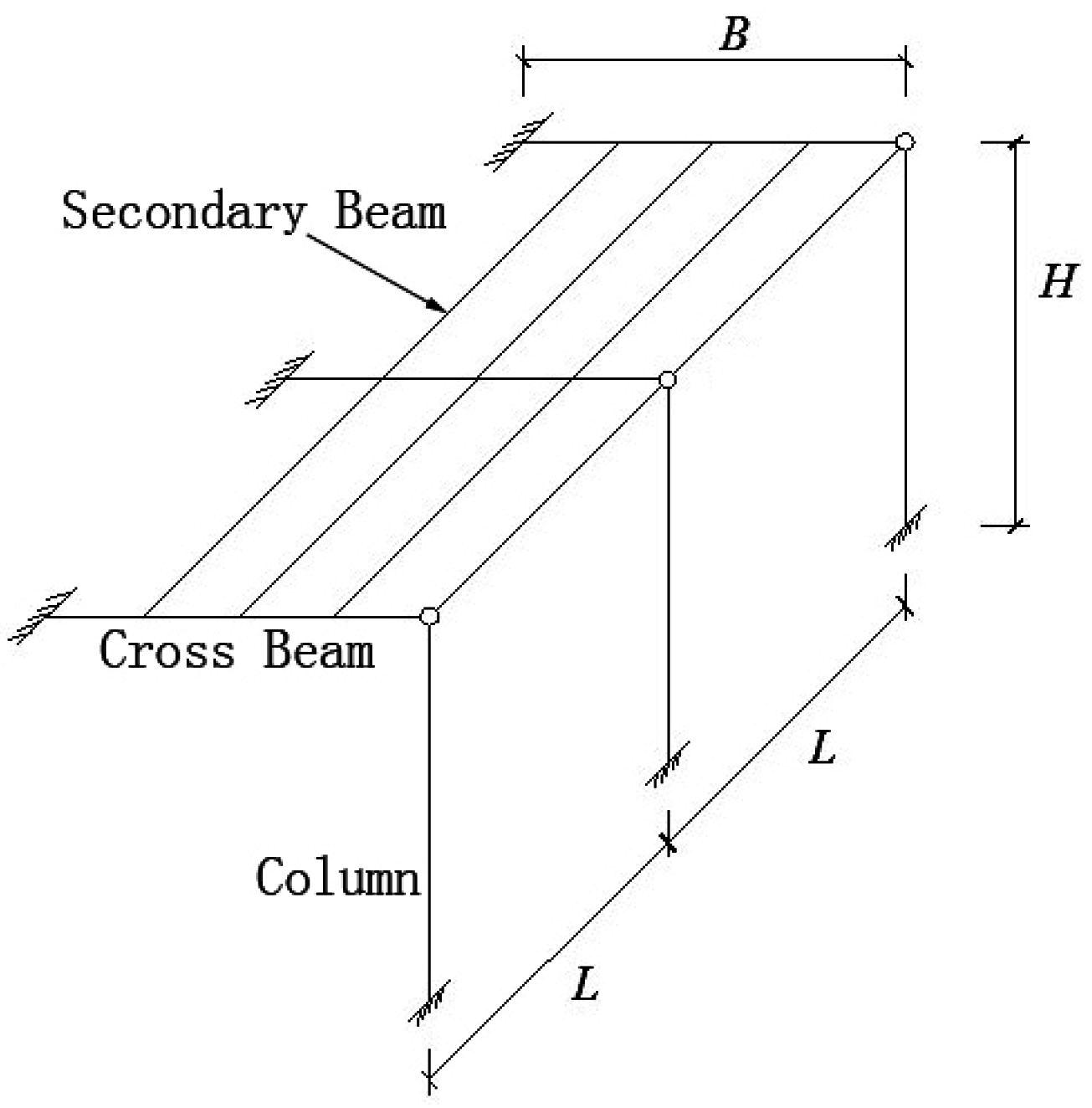
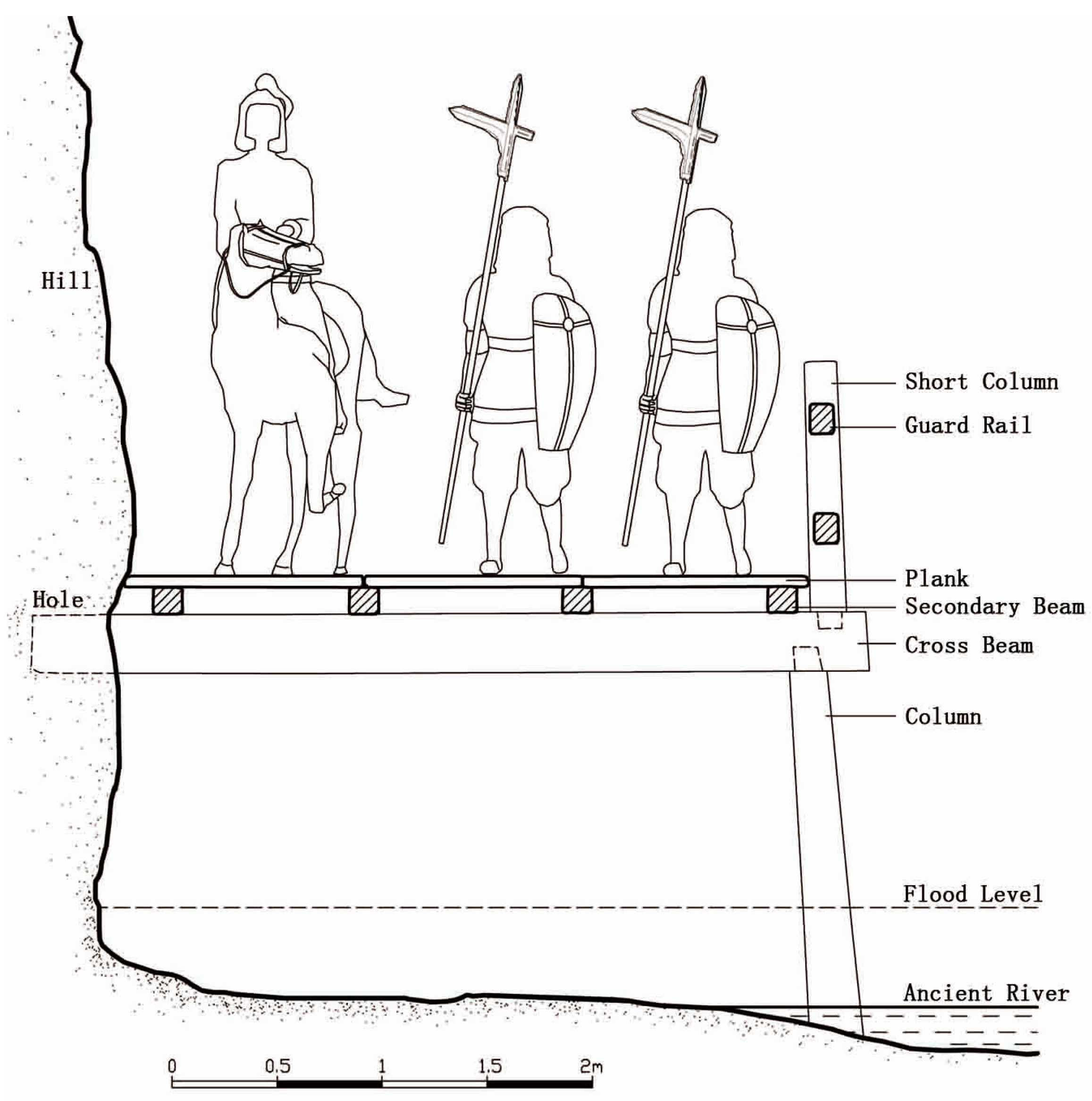
3.3.1. The 3D Model Analysis to Determine the Building form of the Ancient Plank Road

A three-dimensional model is opened in 3Ds Max to number the holes for the plank road and analyze their positional relation to the rock wall with software adopted to measure basic data such as the height of the hole away from the ground, spacing between the holes and hole size to determine the form of the plank road based on documentary records and comprehensive evaluation.
There are 12 lateral square holes from south to north kept on the rock wall of the historic site of the Chiya Plank Road. Since there is only one row of holes kept, its form is therefore impossible to be the crosswise brace type or double cross beam type. According to the record in the Letter to Older Brother Zhuge Jin referenced in the Commentary on the Waterway saying that one end of the pavilion column is inserted into the mountainside and another end is inserted into the water [35], its building form is predominately determined to be cross beam and column type. All data regarding the Chiya Plank Road are surveyed by 3Ds Max and the forms of holes are irregular. In order to make calculations easier, we measure the deepest size of every hole and the spacing between the holes, and, because holes’ boundaries cannot be clearly identified, small deviations may occur in the measurements. The holes are from 27 cm to 30 cm in side length and from 35 cm to 40 cm in depth, as shown in Figure 7, and the majority of holes are from 1.8 m to 3.3 m in spacing. Only the spacing between the No. 3 and No. 4 holes is as much as 8.9 m, as shown in Figure 8. In order to prevent the beam and plank span from being too wide, it is speculated that there may be a column on the ground under the No. 3 and No. 4 holes, with a cross beam installed on the column and not inserted into the mountain, which is similar to the bridge erection principle. Therefore, the restored Chiya Plank Road is cross beam and column type with a cross beam inserted into every hole and a column erected under each beam, on which a longitudinal beam and plank are paved, with a guard rail installed on the outer end of the cross beam. There is an auxiliary cross beam and column support under the longitudinal beam between the No. 3 and No. 4 holes.

3.3.2. Mechanical Analysis to Estimate Geometric Size of the Component

The bending moment and shearing force formulae for primary components such as cross beams, columns and planks are given based on the analysis of the mechanical characteristics of plank road forms to set the variable load generated as a result of troops passing through the plank road, with planks and their mechanical properties for building the plank road set and inquired, respectively. The data and pre-estimated values based on existing historic sites are substituted into the formula to calculate the limit of stress on every component to constantly adjust the pre-estimated value and carry out a checking calculation repeatedly until certain components for the plank road are close to their stress limit to generate a stress estimation table for the plank road based on a summary of various data.
The Chiya Plank Road is a cross beam and column type plank road, being a space structure composed of cross beams, longitudinal beams and columns. Cross beams and longitudinal beams are reduced to lateral plane structures in space, with a permanent load and variable load on the cross beam equivalent to a uniformly distributed load and connections between the components for plank roads being considered as hinge joints in the calculation and connection between the component and the mountain taken as rigid joints. The Chiya Plank Road has no column holes prepared on the ground and, therefore, the connections between the columns and the ground are regarded as hinge joints.
A layout sketch for a cross beam and column type plank road is shown in Figure 9, and the calculation unit plane is shown in Figure 10.

Mechanical Analysis Model for Cross Beams Restoration

Cross beams and columns consist of a statically indeterminate structure; the permanent load g on a cross beam is the dead weight of a cross beam, longitudinal beam and plank, the variable load q is the people and vehicle load and the combined load value is p.
The cross beam is a bending component, which bears the bending moment and the shearing force, the maximum bending moment and maximum shearing force of the cross beam are on the connective section between the cross beam and the mountain, and their values are:
M = p B 2 / 8 V = 5 p B / 8
where M is bending moment (N·m), V is the shearing strength (N), p is the combined load (N), and B is the cantilever length of the cross beam (mm).
The bending bearing capacity of the cross beam shall be calculated according to the following formula:
M W n f m
where fm is the design value (N/mm2) of the bending strength of the plank or stone, M is the design value (Nomm) of the bending moment of the bending component, and Wn is the resisting moment (mm3) of the net section of the bending component.
The shear capacity of the cross beam shall be calculated according to the following formula:
V × S I × b f v
where fv is the design value (N/mm2) of the shearing strength of the plank (along the grain), V is the design value (N) of the shearing force of the bending component, S is the moment of area (mm3) of the sectional area to the neutral axis above the shearing surface, I is the total sectional moment of inertia (mm4), and b is the width of the section of the component (mm).
The column is the axial compression component bearing vertical pressure, and the compression load on the column is:
N = 3 p B / 8
where p is the combined load (N), and B is the cantilever length (mm) of the cross beam.
The column is the round component, and its axial compression bearing capacity based on the strength checking calculation is:
N A n f c
Stability checking calculation:
N φ A 0 f c
where N is the pressure design value (N) of the column, An is the net cross-sectional area of the column (mm2), φ is the stability coefficient of the compression component, A0 is the Cross-sectional area of the column (mm2), and fc is the design value (N/mm) for the compressive strength of the plank (along the grain).

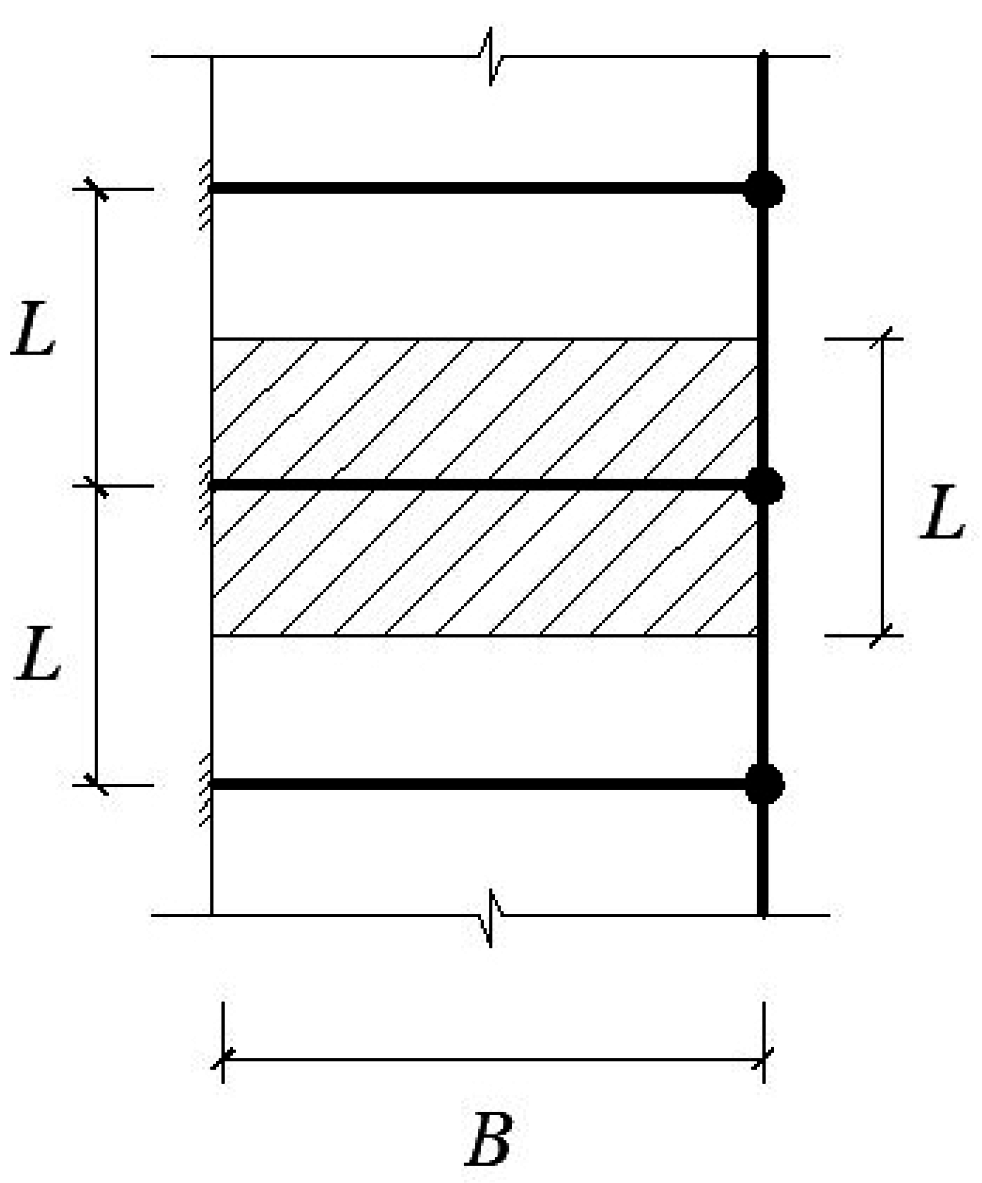
Mechanical Analysis Model for the Longitudinal Beams

The longitudinal beams are reduced to simply supported structures with both ends supported by cross beams, being the bending components. With their maximum bending moment located in the middle of the longitudinal beams, their values are as follows:
M = p L 2 / 8
where M is bending moment (N·m), p is the combined load (N), and L is the spacing between cross beams (mm).
The maximum shear force is located on both ends of the cross beam; its value is as follows:
V = p L / 2
where V is the shearing strength (N), p is the combined load (N), and L is the spacing between cross beams (mm).
Longitudinal beams and cross beams are identical in terms of the checking calculation of the bending bearing capacity and the shear bearing capacity.
For the Chiya Plank Road, it is first necessary to determine the size of some components based on basic data surveyed in the three-dimensional model. For example, the size of the cross beam is determined by the size of the hole for the plank road, and the spacing between the cross beams is determined by the spacing between the holes for the plank road. Next, other data for the plank road are set manually, such as the type of plank, the safety factor, the cantilever length of the cross beam, etc. and then these data are substituted into the aforementioned calculation formulae to calculate whether their stress indicators are up to the limit and then the manually set data values are subjected to constant adjustment until certain components are close to the stress limit. The evidence based data and manually set data are referred to as basic technical indicators, which are integrated with the results of the stress on the components obtained by calculation to prepare a basic technical indicator and a stress estimation table, as shown in Table 1.

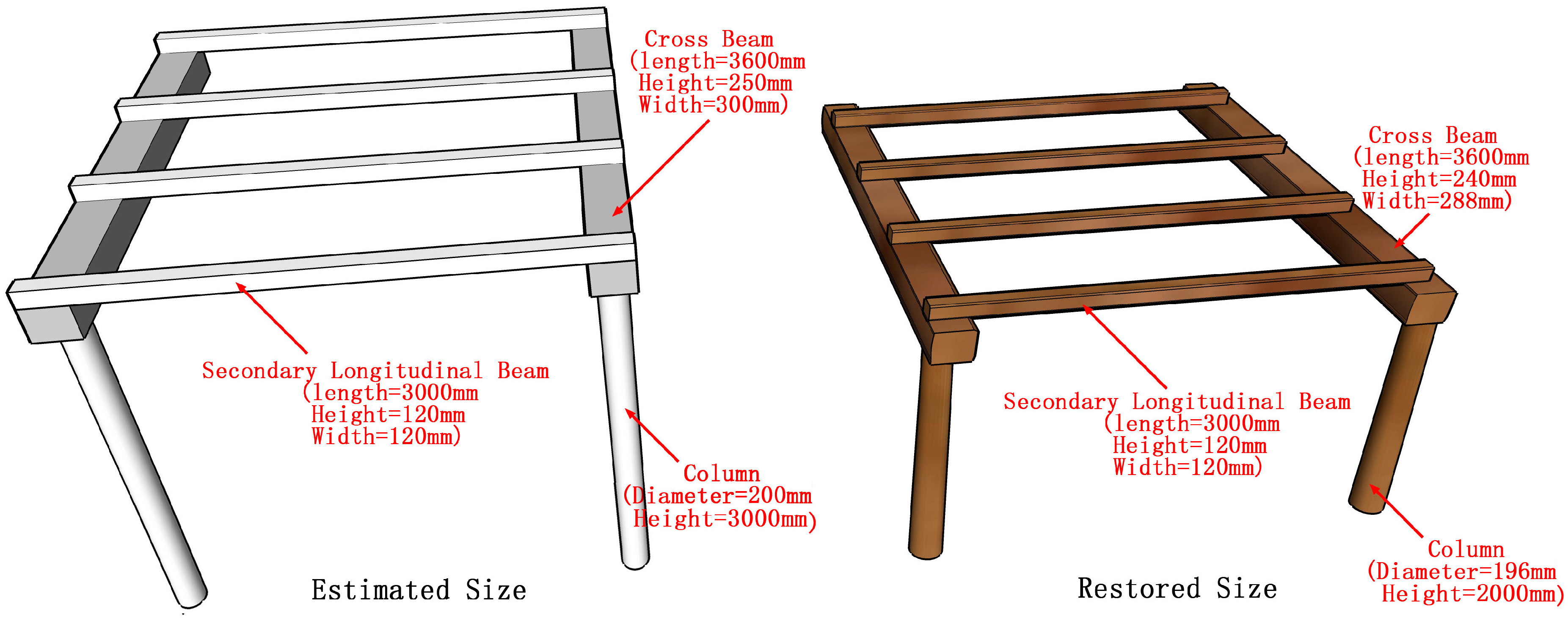
3.3.3. Components Restoration

The plank road component size is based on the site model with precision 3D data and the prior stress estimation. Moreover, the ruler of Shu Kingdom in the Three-Kingdom Period is also important for us, because it may be used in the Chiya Plank Road design.
It is observed from the Chinese Technology History Measurement Volume that 1 Cun (Chinese length unit) is 2.4 cm, 1 Chi (Chinese length unit which is equal to 10 Cun) is almost equivalent to 24 cm, and 1 Zhang (Chinese length unit which is equal to 10 Chi) is 2.4 m [36].
According to Table 1, the Chiya Plank Road cantilever length should not be more than 3.6 m, so it is determined to be 1.5 Zhang (3.6 m). The width may be available for five soldiers marching in extend file formation; and a troop of 20,000 soldiers marching on the plank road may stretch for 5 km in length. The height of the primary cross beam section should not be more than 25 cm, so it is determined to be 1 Chi (24 cm), and its width should not overpass 30 cm, which is determined to be 1.2 Chi (28.8 cm). There are four secondary beams paved on every primary beam and three planks paved on every secondary beam, the height and width of the section of the secondary beam should not be more than 12 cm. Therefore, it is determined to be half a Chi (12 cm). According to results presented in the Table 1, the plank thickness should not be less than 3 cm, so it is determined to be 1.5 Cun (3.6 cm). The column length should not be more than 3 m, but actually its height should be 2 m (the height from the holes to the ground is about 2 m). This indicates that the column stability is more in restoration than in estimation. The column diameter is determined to be 8 Cun (19.6 cm). There is a guard rail for which the tie beam is composed of two pieces or an upper piece and a lower piece on the outside of the plank road, and is determined to be 4 Cun (9.6 cm) in height and 3 Cun (7.2 cm) in width. The Comparison between the Chiya Plank Road’s estimated size and restored size is shown in Figure 11.

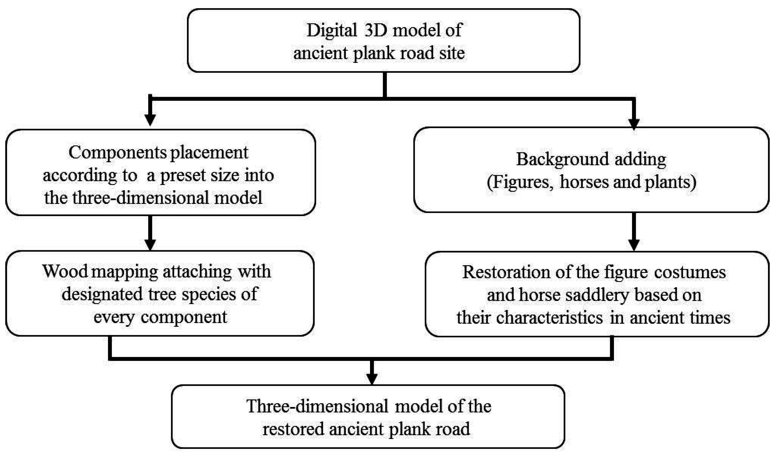
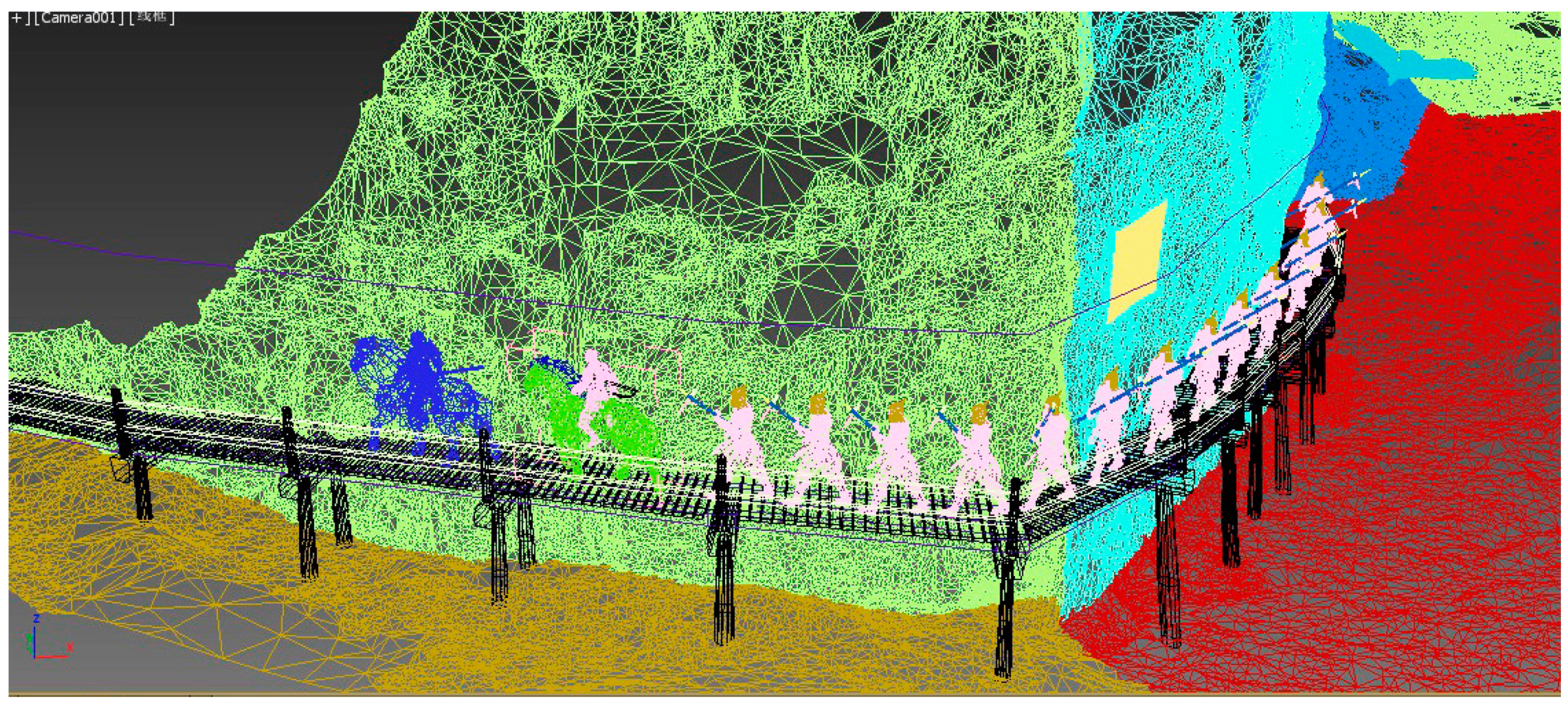
3.3.4. Integration of the Components and Background Scenes for the 3D Model of Chiya Plank Road

The detailed steps for virtual restoration of the ancient plank roads and the restoration achievedn are shown in Figure 12.
The three-dimensional model for the existing historic site of the Chiya Plank Road was opened by 3Ds Max, the wooden cross beams are fabricated according to the set size of components and then they are inserted into the corresponding holes for the plank road, and then components such as the column, secondary beam, plank and guard rail are fabricated based on the size of the cross beam afterwards to install them in the model correctly.
After the completion of the fabrication of the components for the plank road, the suitable background scene including figure, horse, plants, and flying birds are added to the three-dimensional model to offer a direct-viewing reference for the plank road and also improve the fidelity of scene. The process to add components and background scenes to the Chiya Plank Road is shown in Figure 13.

4. Results and Discussions

4.1. Restoration Result of the Chiya Plank Road

The realistic effect chart with a high definition is obtained after the achievement in restoration has been rendered by 3Ds Max and processed by Photoshop, which will also be fabricated into animation by rendering many occasions. In addition, the achievement in restoration may also educe route in dwg format by 3Ds Max, which is also available for editing and fabrication of the plane, elevation and section in Auto CAD. After the rendering and processing of the Chiya Plank Road Model, the restoration effect chart, as shown in Figure 14, is created, and the structure style, as shown in Figure 15, is produced. It may be redrawn into sections for restoration by importing the model into CAD, as shown in Figure 16.

4.2. Discussions

4.2.1. Restoration Calculus Checking

The outcome in restoration is in accordance with the record in the Commentary on the Waterway in terms of the form of the plank road, indicating that it has higher credibility in terms of appearance. The size of every component of Chiya Plank Road given in the outcome is within the range of the stress-bearing capability of wood, as shown in Table 2, indicating that the plank road could have actually been built.
The precise size of every component in the outcome is set according to half a multiple or integral multiple of the building ruler adopted in the Shu Kingdom in the Three-Kingdom Period. Such methods to set the size have no reliable evidence for support, but there is no better solution other than this method with the full sized figures and horses added to the plank road models mentioned in the outcome of restoration, showing harmonious proportion between the plank road and the troops composed of figures and horses indicating that the relative scale of plank road to user is reasonable. The scene of the troops’ rapid march through the plank road shown in the restoration effect chart tallies with the fact of frequent use of the plank road in the Shu Kingdom in the Three-Kingdom Period, indicating that the effect chart truly reflects the scene in those days to a great extent.
It is observed from the above-mentioned explanations that the restoration outcome is reasonable and beautiful in appearance, having achieved the expected restoration objective. The restoration is based on heritage sites’ current situation; it uses the precision 3D data with no photographs or sketches; and is different from the traditional way, which is called imaginative restoration.

4.2.2. Added Value of Method

The restoration strategy is different from traditional strategies because it uses both the precision 3D Data analysis and mechanical analysis in order to carry out a 3D model renovation. The restoration data are substituted into the formula to calculate on every component’s stress limit. We constantly adjust the pre-estimated value and repeatedly carry out a checking calculation until certain plank road components are close to their stress limits. The dynamic feedback provides a new way to renovate a heritage site, and in case the information is not enough, it can consider advance estimation to find the suitable numbers.

4.2.3. Defects and Uncertainties

The restoration strategy is able to achieve a proper plank road analysis and restoration. Therefore, the following defects are raised: First, the plank road memorial site may not be a complete picture of the original plank road and there may be a loss of information to a certain extent. Second, the plank road structural analysis is only able to determine the plank road’s reasonable size within a certain range but unable to infer the plank road component’s precise size and it is necessary to carry out a preliminary estimation to cope with such issues. Third, there is an estimation which is made during the setting of components size to a certain extent, and this is to be improved on. The research will be obviously improved in the case that more information about the site is discovered, but now no more evidence can be provided to support all the put forward assumptions.

5. Conclusions

The precision of the restoration of ancient plank roads is dependent on the precision of the model generated based on surveying and mapping. The precision of the Chiya Plank Road Model for the hole areas is within 0.5 cm, which is clearly superior to the precision necessary for the restoration of other similar historic sites, with the scene for model building for the restoration of historic sites being almost a recurrence of the historic site environment and restoration steps being based almost on the actual building process, the appearance and usage of the ancient plank road are restored to a great extent. The proposed virtual restoration of Chiya Plank Road can achieve a proper analysis and restoration of the plank road, however the historic site of the plank road may not be a complete picture of the original plank road and there may be a loss of information to a certain extent. In addition, the structural analysis of the plank road is only able to determine the reasonable size of the plank road within a certain range but unable to infer the precise size of the component of the plank road and it is necessary to carry out a preliminary estimate.
The achievement in the restoration has unprecedented advantages over previous ones in restoration in terms of precision and reliability, which can serve as a key reference for relevant research and also indicate that it is effective and feasible to adopt a three-dimensional digital model generated by precision measurement to carry out the restoration of ancient sites.

Acknowledgments

The authors would like to thank “The Compass Plan” supported by State Administration of Cultural Heritage. This research is also supported by National Natural Science Foundation of China (Grant No. 41271452), Key Technologies R&D Program of China (Grant No. 2015BAK03B04), and The Fundamental Research Funds for the Central Universities (Chang’an University) (Grant No. 310841161002).

Author Contributions

Siliang Chen conceived the study and wrote the paper, did the field data collection and data processing, implemented 3D modeling and accuracy analysis; Qingwu Hu conceived the study; Shaohua Wang implemented the 3D rendering; and Hongjun Yang verified the results and arranged the materials.

Conflicts of Interest

The authors declare no conflict of interest.

References

  1. Liu, W.A.; Ren, G. The New Study of the Ruin of Ninghe Ancient Plank Road. Salt Ind. 2003, 2013–2015, 9–24. (In Chinese) [Google Scholar]
  2. Miller, F.P.; Vandome, A.F.; Mcbrewster, J. Ancient Chinese Wooden Architecture; Alphascript Publishing: Beau Bassin, Mauritius, 2010. [Google Scholar]
  3. Surhone, L.M.; Timpledon, M.T.; Marseken, S.F. Plank Road; Betascript Publishing: Beau Bassin, Mauritius, 2010. [Google Scholar]
  4. Wang, C.; Li, X. Design and Actualization of Urban Planning Information System Combining 2D GIS and 3D Simulation. Urban Geotech. Investig. Surv. 2008, 3, 10–13. [Google Scholar]
  5. Zhang, N. Research and Realization of 2D Geological Modeling Based on GIS; China University of Petroleum: Beijing, China, 2007. [Google Scholar]
  6. Cheng, B.; Xiao, H. 3D Object-oriented Scene Creation and GIS Data Management. Geomat. World 2004, 3, 25–28. [Google Scholar]
  7. Zhu, Q. 3D GIS and Its Application in Smart City. J. Geo-Inf. Sci. 2014, 2, 151–157. [Google Scholar]
  8. Wang, S. Application and Analysis of Surveying Technology of low altitude UAV Aero-photography and Remote Sensing in Surveying Field. Heilongjiang Sci. Technol. Inf. 2016, 8, 60. (In Chinese) [Google Scholar]
  9. Jun, Y.; Shaohua, W.; Jiayuan, L. Research on Fine Management and Visualization of Ancient Architectures Based on Integration of 2D and 3D GIS Technology. IOP Publ. 2014, 17, 012168. [Google Scholar] [CrossRef]
  10. Zheng, D.; Yang, L. Collecting System of Building Surface Data with Three-D Laser Scanning Survey Aided with Digital Photogrammetry. Build. Sci. 2004, 4, 75–79. [Google Scholar]
  11. Hong, O. Research on 3D Digital Modeling Method of Ancient Architecture in the Palace Museum. J. Beijing Union Univ. Nat. Sci. 2015, 3, 10–14. (In Chinese) [Google Scholar]
  12. Wang, F.; Song, Y.; Gao, Z.; Zeng, F. Application of UAV Aerial Surveying and TLS Technology to Surveying and Modeling in Historic site of Guangzhou Steel Works. Bull. Surv. Mapp. 2016, 4, 72–74. [Google Scholar]
  13. Domingo, I.; Villaverde, V.; López-Montalvo, E. Latest developments in rock art recording: Towards an integral documentation of Levantine rock art sites combining 2D and 3D recording techniques. J. Archaeol. Sci. 2013, 40, 1879–1889. [Google Scholar] [CrossRef]
  14. Hinzen, K.G.; Schreiber, S.; Rosellen, S. A high resolution laser scanning model of the Roman theater in Pinara, Turkey—Comparison to previous measurements and search for the causes of damage. J. Cult. Herit. 2013, 14, 424–430. [Google Scholar] [CrossRef]
  15. Guidi, G.; Russo, M.; Angheleddu, D. 3D survey and virtual reconstruction of archeological sites. Digit. Appl. Archaeol. Cult. Herit. 2014, 1, 55–69. [Google Scholar] [CrossRef]
  16. Hu, Q.; Wang, S.; Fu, C.; Ai, M.; Yu, D.; Wang, W. Fine Surveying and 3D Modeling Approach for Wooden Ancient Architecture via Multiple Laser Scanner Integration. Remote Sens. 2016, 8, 270. [Google Scholar] [CrossRef]
  17. Pesci, A.; Casula, G.; Boschi, E. Laser scanning the Garisenda and Asinelli towers in Bologna (Italy): Detailed deformation patterns of two ancient leaning buildings. J. Cult. Herit. 2011, 12, 117–127. [Google Scholar] [CrossRef] [Green Version]
  18. Kuzminsky, S.C.; Gardiner, M.S. Three-dimensional laser scanning: Potential uses for museum conservation and scientific research. J. Archaeol. Sci. 2012, 39, 2744–2751. [Google Scholar] [CrossRef]
  19. Chellini, G.; Nardini, L.; Pucci, B. Evaluation of seismic vulnerability of Santa Maria del Mar in Barcelona by an integrated approach based on terrestrial laser scanner and finite element modeling. Int. J. Arch. Herit. 2014, 8, 795–819. [Google Scholar] [CrossRef]
  20. Li, S.; Hou, M.; Wu, Y.; Hu, Y.; Zhang, Y. 3D Information Recording and Application of Rock Relics. Urban Geotech. Investig. Surv. 2013, 2, 85–88. [Google Scholar]
  21. Kontogianni, G.; Georgopoulos, A.; Saraga, N.; Alexandraki, E.; Tsogka, K. 3D Virtual reconstruction of the middle Stoa in the Athens ancient Agorà. ISPRS Arch. Photogramm. Remote Sens. Spat. Inf. Sci. 2013, xl-5/w1, 125–131. [Google Scholar] [CrossRef]
  22. Dore, C.; Murphy, M.; McCarthy, S.; Brechin, F.; Casidy, C.; Dirix, E. Structural simulations and conservation analysis-Historic building information model (HBIM). Int. Arch. Photogramm. Remote Sens. Spat. Inf. Sci. 2015, XL-5/W4, 351–357. [Google Scholar] [CrossRef]
  23. Oreni, D.; Brumana, R.; Della Torre, S.; Banfi, F.; Previtali, M. Survey turned into HBIM: the restoration and the work involved concerning the Basilica di Collemaggio after the earthquake (L’Aquila). ISPRS Ann. Photogramm. Remote Sens. Spat. Inf. Sci. 2014, II-5, 267–273. [Google Scholar] [CrossRef]
  24. Sánchez-Aparicio, L.J.; Villarino, A.; García-Gago, J.; González-Aguilera, D. Photogrammetric, Geometrical, and Numerical Strategies to Evaluate Initial and Current Conditions in Historical Constructions: A Test Case in the Church of San Lorenzo (Zamora, Spain). Remote Sens. 2016, 8, 60. [Google Scholar] [CrossRef]
  25. Tang, H. Science and Civilisation in China, Volume of Bridge; Science Press: Beijing, China, 2000; p. 152. (In Chinese) [Google Scholar]
  26. Wang, K. History of Ancient Road in Shaanxi Province; China People’s Communications Press: Beijing, China, 1989. (In Chinese) [Google Scholar]
  27. Wang, P. Shu Road of China; China Travel & Tourism Press: Beijing, China, 2008. (In Chinese) [Google Scholar]
  28. Gao, C.; Wang, J.; Wang, X.; Hu, F. Roads Converge on Chang’an, the Trip of Cultural Geography of Ancient Roads in Qinling; Northwest University Press: Xi’an, China, 2010. (In Chinese) [Google Scholar]
  29. Guidi, G.; Remondino, F.; Russo, M. A multi-resolution methodology for the 3D modeling of large and complex archeological areas. Int. J. Arch. Comput. 2009, 7, 39–55. [Google Scholar] [CrossRef]
  30. Revaud, J.; Weinzaepfel, P.; Harchaoui, Z.; Schmid, C. DeepMatching: Hierarchical Deformable Dense Matching. Int. J. Comput. Vis. 2015, 2, 1–24. [Google Scholar] [CrossRef] [Green Version]
  31. Haala, N.; Rothermel, M. Dense multiple stereo matching of highly overlapping UAV imagery. ISPRS Int. Arch. Photogramm. Remote Sens. Spat. Inf. Sci. 2012, XXXIX-B1, 387–392. [Google Scholar] [CrossRef]
  32. Torres-Martínez, J.A.; Seddaiu, M.; Rodríguez-Gonzálvez, P.; Hernández-López, D.; González-Aguilera, D. A Multi-Data Source and Multi-Sensor Approach for the 3D Reconstruction and Web Visualization of a Complex Archaelogical Site: The Case Study of “Tolmo De Minateda”. Remote Sens. 2016, 8, 550. [Google Scholar] [CrossRef]
  33. Besl, P.J.; McKay, N.D. Method for registration of 3-D shapes. IEEE Trans. Pattern Anal. Mach. Intell. 1992, 14, 239–256. [Google Scholar] [CrossRef]
  34. Lan, Y. The form and transition of Chinese ancient plank road. Study Hist. Nat. Sci. 1992, 1, 68–76. [Google Scholar]
  35. Li, D. Commentary on the Waterway; Chen, Q., Translator; Zhonghua Book Company: Beijing, China, 2009; p. 223. [Google Scholar]
  36. Qiu, G.; Qiu, L.; Yang, P. Measurement. In Chinese Technology History; Science Press: Beijing, China, 2001; pp. 268–270. (In Chinese) [Google Scholar]
Figure 1. Chiya Plank Road Site.
Remotesensing 08 00828 g001
Figure 2. Image of the hole areas on the Chiya Plank Road Site.
Remotesensing 08 00828 g002
Figure 3. Proposed idea for the 3D restoration of Chiya Plank Road Site.
Remotesensing 08 00828 g003
Figure 4. Designing a process for the digital model for the ancient plank road site.
Remotesensing 08 00828 g004
Figure 5. Three-dimensional model of the existing Chiya Plank Road Site.
Remotesensing 08 00828 g005
Figure 6. Preparing a process for model analysis and a restoration program of the ancient plank road site.
Remotesensing 08 00828 g006
Figure 7. Depth of the No. 12 hole in the Chiya Plank Road in 3Ds Max.
Remotesensing 08 00828 g007
Figure 8. Space between the No. 3 and No. 4 holes on the Chiya Plank Road in 3Ds Max.
Remotesensing 08 00828 g008
Figure 9. Creating a structural layout of the cross beam and column type plank road.
Remotesensing 08 00828 g009
Figure 10. Planning for the calculation element of the cross beam and column plank road.
Remotesensing 08 00828 g010
Figure 11. Compare the estimated size with the restored size of plank road.
Remotesensing 08 00828 g011
Figure 12. Processing of the virtual restoration of the ancient plank road and showing its results.
Remotesensing 08 00828 g012
Figure 13. Adding of the components and the background of the plank road to a three-dimensional model.
Remotesensing 08 00828 g013
Figure 14. Result of the virtual restoration for the Chiya Plank Road.
Remotesensing 08 00828 g014
Figure 15. Part of Structure style of the Chiya Plank Road.
Remotesensing 08 00828 g015
Figure 16. Viewing of the sectional restoration of the Chiya Plank Road.
Remotesensing 08 00828 g016
Table 1. Technical indicator and estimation of stress on the cross beam and column type plank.
Technical Indicator of Cross Beam and Column Type Plank RoadValueValue Type
Wood (Spruce) density ρ (g/cm3)0.33set value
Spacing between cross beams L (mm)3000set value
Cantilever length B (mm)3600set value
Height of primary cross beam h (mm)250set value
Width of primary cross beam b (mm)300set value
Number of longitudinal beams paved on every cross beam4set value
Height of section of secondary longitudinal beam h1 (mm)120set value
Width of section of secondary longitudinal beam b1 (mm)120set value
Plank thickness d1 (mm)30set value
Preset safety factor k3set value
Permanent load g (N/mm)0.70caculated value
Variable load q (N/mm)12calculated value
Total load p(g + q) (N/mm)12.70calculated value
Total load on every plank road P (N)45,730.44calculated value
Checking of bending strength of primary cross beam k × M/W (it shall be ≤FM)19.76 ≤ 49.8calculated value
Checking of bending strength of secondary longitudinal beam k × M1/W1 (it shall be ≤fm)44.66 ≤ 49.8calculated value
Checking of bending strength of plank k × M2/W2 (it shall be ≤fm)43.20 ≤ 49.8calculated value
Checking of shearing strength of primary cross beam k × VS/(I × b) (it shall be ≤fv)1.71 ≤ 5calculated value
Checking of shearing strength of secondary longitudinal beam k × V1 × S1/(I1 × b1) (it shall be ≤fv)1.79 ≤ 5calculated value
Column diameter D (mm)200set value
Column length L13000set value
Checking of compression strength of column k × N/An (it shall be ≤fc)1.64 ≤ 27.6calculated value
Column length factor μ1calculated value
Slenderness ratio λ60.00calculated value
Stability coefficient Φ0.54calculated value
Checking of stability of column under stress K × N/(Φ × A0) (it shall be ≤fc)3.03 ≤ 27.6calculated value
Table 2. Technical indicator and stress on the Chiya Plank Road.
Technical Indicator of Chiya Plank RoadValue of Chiya Plank Road
Wood (Spruce) density ρ (g/cm3)0.33
Spacing between cross beams L (mm)3000
Cantilever length B (mm)3600
Height of primary cross beam h (mm)240
Width of primary cross beam b (mm)288
Number of longitudinal beams paved on every cross beam 4
Height of section of secondary longitudinal beam h1 (mm)120
Width of section of secondary longitudinal beam b1 (mm)120
Plank thickness d1 (mm)36
Preset safety factor k3
Permanent load g (N/mm)0.74
Variable load q (N/mm)12.00
Total load p(g + q) (N/mm)12.74
Total load on every plank road P (N)45,874.43
Checking of bending strength of primary cross beam k × M/W (it shall be ≤fm)22.40 ≤ 49.80
Checking of bending strength of secondary longitudinal beam k × M1/W1 (it shall be ≤fm)44.80 ≤ 49.80
Checking of bending strength of plank k × M2/W2 (it shall be ≤fm)30.00 ≤ 49.80
Checking of shearing strength of primary cross beam k × VS/(I × b) (it shall be ≤fv)1.87 ≤ 5
Checking of shearing strength of secondary longitudinal beam k × V1 × S1/(I1 × b1) (it shall be ≤fv)1.79 ≤ 5
Column diameter D (mm)196
Column length L12000
Checking of compression strength of column k × N/An (it shall be ≤fc)1.36 ≤ 27.6
Column length factor μ1
Slenderness ratio λ36.73
Stability coefficient Φ0.76
Checking of stability of column under stress K × N/(Φ × A0) (it shall be ≤fc)2.26 ≤ 27.6

