Article

Analysis and Experiments of an Electromagnetic Docking Mechanism for Repeated Docking and Separation of the CubeSats

1
School of Mechatronics Engineering, Harbin Institute of Technology, Harbin 150001, China
2
Harbin Space Star Data System Technology Co., Ltd., Harbin 150028, China
*
Author to whom correspondence should be addressed.
Remote Sens. 2025, 17(8), 1446; https://doi.org/10.3390/rs17081446
Submission received: 11 February 2025 / Revised: 30 March 2025 / Accepted: 16 April 2025 / Published: 17 April 2025
(This article belongs to the Special Issue Advances in CubeSats for Earth Observation)

Abstract

:
With the background of on-orbit repetitive connection and separation of CubeSats, an electromagnetic docking mechanism for repeated docking and separation is proposed. A reusable electromagnetic docking scheme combining lead screw transmission with electromagnets is introduced. The electromagnetic force/torque model and the attitude model of the CubeSat are derived based on the relationship between force and magnetic flux density in a magnetic field. The coil layout and the polarity of magnetic poles are optimized and analyzed, four different layout configurations are proposed, and their mechanical characteristics are analyzed. A multi-body dynamics simulation analysis of the entire mechanism is conducted to evaluate the attitude correction capability of the electromagnetic attraction separation unit. A three-degrees-of-freedom capture and separation test of the electromagnetic attraction separation unit is carried out in a microgravity-simulated environment to investigate the characteristics of capture and separation under different position and attitude deviation conditions of the energized solenoids. The designed electromagnetic docking mechanism has an adaptive attitude adjustment and docking range of a 30° cone. It can achieve low-impact, high-tolerance, and reusable docking and separation.

1. Introduction

In recent years, with the continuous advancement of micro-mechanical and micro-electronic technologies, as well as the development of various new aerospace materials, the miniaturization of satellites has become a trend in modern satellite development. This trend is particularly evident in the fields of new technology demonstration and validation, as well as in scientific research and teaching, where CubeSats have become an indispensable component [1,2]. CubeSats have been applied in Earth observation and asteroid exploration. Rosero-Montalvo et al. explored their use in Earth’s climate change observations [3], while Quarta et al. analyzed trajectories for asteroid exploration missions [4]. Meanwhile, due to the limitations of existing launch-vehicle technologies and launch costs, the on-orbit assembly and reconfiguration of CubeSats have emerged as a promising alternative for achieving the functions of large spacecraft [5]. Due to the limited fuel capacity of CubeSats and other small spacecraft, on-orbit docking can enable refueling and maintenance services, effectively extending their operational lifespan. As a key technology for on-orbit assembly and reconfiguration, rendezvous and docking technology will increase demand for missions requiring these capabilities.
Space rendezvous and docking technology refers to the process where two spacecraft in orbit, sharing the same spatial position within the same orbital plane, approach each other at a certain relative velocity and ultimately achieve a rigid connection, forming a single structural entity [6]. This technology is a prerequisite for various space missions, including the functional reconfiguration of space vehicles, on-orbit maintenance, and on-orbit refueling [7]. Through rendezvous and docking, modular spacecraft can be assembled in orbit, and repeated docking and separation can enable functional reconfiguration and on-orbit repeated refueling. Numerous studies and mature space engineering applications exist regarding space rendezvous and docking technology. Underwood et al. investigated the feasibility of using CubeSat technology for autonomous space telescope assembly [8]. Fabrizio employed model predictive control strategies to achieve precise docking between CubeSats and large spacecraft [9]. Xiangtian and Shijie proposed adaptive saturation control methods to address rendezvous and docking issues under motion constraints [10]. Typical examples of this technology include the assembly of the International Space Station (ISS) and the docking between China’s Tiangong-1 space station and the Shenzhou-8 spacecraft [11]. However, traditional docking mechanisms, which rely primarily on inertia during the final docking phase, often generate significant impact forces that can pose many potential hazards. Moreover, to meet the demand for on-orbit separation after docking, additional separation mechanisms and power sources for release are required [12]. Compared to traditional space rendezvous and docking mechanisms, electromagnetic docking technology provides docking forces through electromagnetic interactions, eliminating the need for additional propellant consumption and avoiding plume contamination. It can achieve gentle, low-impact docking through control strategies [13]. Moreover, it requires no complex mechanisms and can be reused multiple times through the system power supply, meeting the needs for the miniaturization and repeatable docking of small spacecraft in orbit.
Repeatable docking and separation mechanisms are crucial for enhancing the on-orbit capabilities of CubeSats. Due to their lightweight and small volume, CubeSats have limited capacity for carrying fuel, power supplies, and payloads. Repeatable docking and separation technology allows CubeSats to replace batteries, repair faulty equipment, and even add new sensors for functional upgrades after docking. This significantly extends the operational lifespan and improves the performance of CubeSats [14,15]. This technology also enables multiple autonomous docking and separation maneuvers, facilitating formation flying and dynamic reconfiguration based on mission needs. This enhances Earth observation capabilities, improves efficiency and coverage, and allows rapid reconfiguration for urgent tasks like natural-disaster monitoring.
Current research has technically demonstrated the feasibility of electromagnetic docking. The SPHERES (Synchronized Position Hold Engage Re-orient Experimental Satellites) [16] project, one of the earliest electromagnetic docking initiatives, conducted numerous on-orbit experiments aboard the International Space Station. The ELSA-d mission demonstrated electromagnetic docking between a service and client spacecraft, showcasing the ability to locate and dock with space debris, which is useful for debris removal [17]. Existing technologies typically use coils or electromagnets, varying in number and configuration, to dock or separate spacecraft by adjusting current intensity and direction. The FELD (Flexible Electromagnetic Leash Docking system) [18] project combined a flexible tether with electromagnets to capture target payloads, avoiding collisions with the host spacecraft, but it faced challenges in tether control, leading to lower docking success rates and significant impact forces to the target during release. The USED (Ultra-Soft Electromagnetic Docking) [19] project utilized two electromagnetic coils for docking, offering a simple structure with centimeter-level precision, though it required a central claw on the docking face for final capture, which added considerable mass. The PACMAN (Position and Attitude Control with Magnetic Navigation) [20] project featured a large coil on the target and four smaller coils on the host spacecraft. The target coil generated a constant magnetic field, simplifying control but limiting angular deviation adjustment and restricting docking distance to within 200 mm due to power constraints. Ruan et al. designed a micro/nanosatellite electromagnetic docking device, initially using two iron-core electromagnets and later a configuration of one large and four small coils on one side, and one large and ten small coils on the other [21,22,23]. This multi-coil setup enhanced pose adjustment and docking efficiency but increased control complexity and system power requirements. In terms of control methodologies, significant research has been conducted as well. Zhang et al. analyzed magnetic force/torque symmetry and self-localization capabilities based on nonlinear relative motion dynamics, deriving automatic magnetic dipoles to provide a foundation for electromagnetic docking control [24]. Vilvanathan et al. developed a sequential control method for CubeSat electromagnetic docking, effectively addressing attitude deviation issues [25]. Liu et al. addressed electromagnetic docking delays in elliptical orbits using active disturbance rejection control, improving adaptability in complex orbital environments [26]. Overall, while extensive research exists, in-orbit validation of electromagnetic docking technologies remains limited, with no mature engineering applications yet available. Most studies on control strategies and configurations remain in theoretical or laboratory testing phases [27,28]. Moreover, there is a need for further research and analysis in the selection and design of new configurations that utilize electromagnetic forces/torques for repeatable connection and separation, as well as in the theoretical analysis of tolerance performance.
This study employs electromagnetic forces and torques as the driving mechanism for docking and attitude adjustment, consistent with existing electromagnetic docking technologies, enabling controllable docking through the regulation of current magnitude and direction. A novel reusable electromagnetic docking scheme is proposed, which integrates lead screw transmission with electromagnets to combine electromagnetic docking with mechanical transmission, thereby optimizing docking mechanism performance while maintaining a compact structural design. Innovatively, a novel configuration is introduced where both the subsatellite and mother-satellite utilize four energized solenoids mounted at the four corners of their docking interfaces. The influence of magnetic pole distribution patterns on docking effectiveness is systematically analyzed. Compared to conventional electromagnetic docking architectures, this configuration demonstrates enhanced flexibility in compensating for position and attitude deviations, while its simplified structure facilitates subsequent control strategy development.
This paper focuses on the research of electromagnetic repeatable docking and separation mechanisms applicable to CubeSats, with the background of mother-satellite and subsatellite on-orbit repeatable docking and separation. The objective is to develop a docking technology that features gentle docking, rigid locking, low-impact separation, and a certain level of tolerance capability. This involves designing the repeatable docking and separation mechanism and its functional components, establishing electromagnetic force/torque models, optimizing coil layout, and studying the electromagnetic characteristics and capture capabilities of the mechanism through simulation and capture–separation tests. The research findings of this study are expected to be applied in the fields of on-orbit servicing of CubeSats and on-orbit assembly and separation of formation-flying CubeSats in the future, providing technical support for the expansion of CubeSats’ capabilities in Earth observation, navigation, and communication.
The remainder of this paper is organized as follows: Section 2 introduces the overall structure and working principle of the electromagnetic repeatable docking and separation system. Section 3 establishes the electromagnetic force/torque model and the attitude model of the CubeSat. Section 4 optimizes the layout of the energized solenoids on the docking interface and the distribution of current directions to improve docking and separation efficiency. Section 5 conducts a multi-body dynamics simulation analysis of the system, evaluates the impact of the electromagnetic field, and validates the docking and separation functions and the docking range through the electromagnetic attraction separation unit captive separation test. Finally, Section 6 concludes the paper.

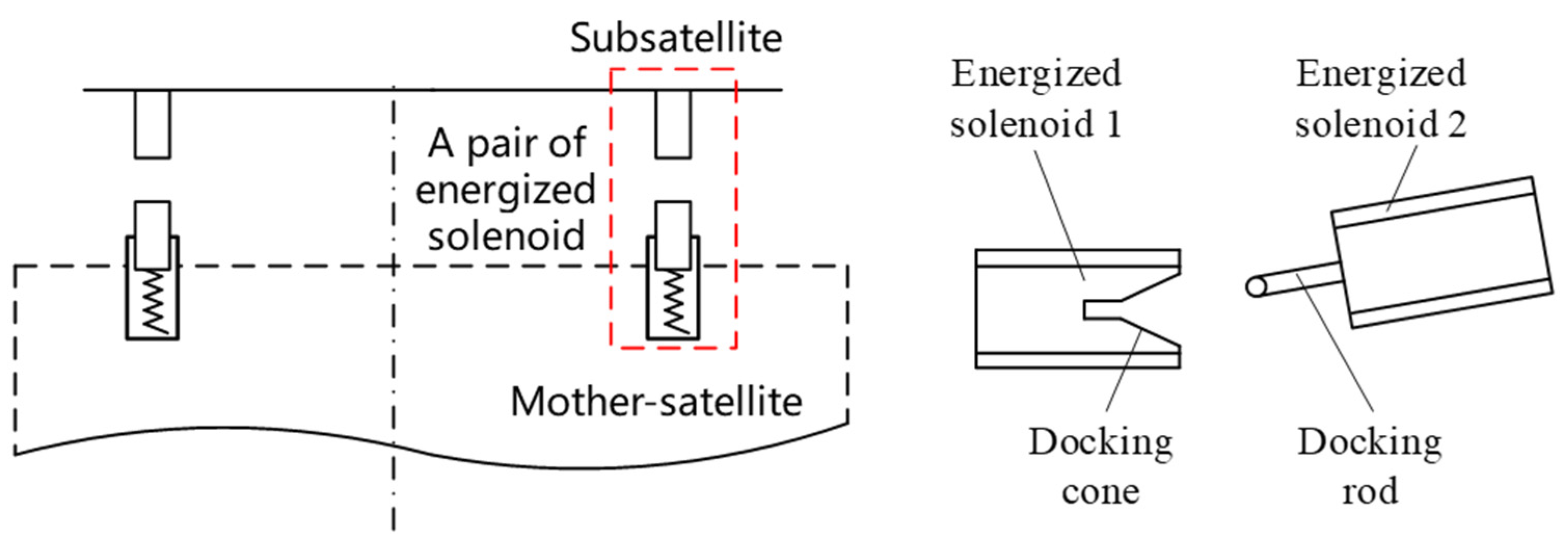
2. Structure and Working Principle

The repeatable docking and separation mechanism is situated on the on-orbit servicing platform of the mother-satellite. The on-orbit servicing platform of the mother-satellite maneuvers to the preset position in the docking orbit. The subsidiary satellite utilizes its thrusters to propel itself to the designated location, relying on electromagnetic forces to enter the capture volume. Once the positional error is completely calibrated, the locking components within the repeatable docking and separation mechanism commence operation until the desired preload force is achieved. After full locking is attained, the motor is powered down, and the locked state can be reliably maintained for an extended period.
The electromagnetic attraction separation unit, along with the rigid locking unit, are integral components of the docking mechanism. The electromagnetic attraction separation unit utilizes an energized solenoid with an iron core, arranged on the mating surfaces of the mother-satellite and subsatellite. Specifically, the solenoid on the mother-satellite’s mating surface is equipped with a buffer spring, which allows for better alignment and contact between the cross-sections of the two energized solenoids, thereby increasing the electromagnetic attraction force. The iron core within the energized solenoid 1 is partially hollowed out to form a docking cone, which reduces weight without significantly detracting from the magnetic field strength, as depicted in Figure 1.
After the electromagnetic attraction separation unit completes the capture of the subsatellite, the rigid locking unit begins to work and carries out the rigid locking of the subsatellite. After completing the rigid locking, the disc spring component in the rigid locking unit carries out the reliable maintenance of the force load. The rigid locking unit is horizontally arranged on the on-orbit servicing platform of the mother-satellite, which can reduce the axial occupied space of the docking mechanism, release more internal space of the mother-satellite, and facilitate the overall layout of the mother-satellite. As shown in Figure 2, due to the need for long-distance linear movement, a lead screw mechanism is used to reduce the occupied space of the mechanism and ensure the deceleration and force increase effect of the mechanism. The rigid locking unit is composed of plungers, connecting rods, screw nuts, a double-ended screw, bevel gears, and a motor.
The working process is as follows: After the completion of the capture and attitude adjustment actions, the motor drives the double-ended screw, which in turn moves the screw nuts upward and downward, respectively. The connecting rods, which are hinged to the screw nuts, push the plungers to move leftward and rightward, respectively. The clamping force is applied through the disc spring. At this point, the motor is de-energized, and the lead screw achieves self-locking. Meanwhile, the connecting rods are perpendicular to the lead screw at an angle of 90°, which enables the system to maintain a locked state for an extended period after the motor is de-energized, awaiting the ground command for the next separation requirement. The unlocking process is the reverse of the locking process. After the unlocking, the same direction current is supplied to the energized solenoid, generating an electromagnetic repulsive force between them. This electromagnetic repulsive force is utilized to separate the subsatellite from the mother-satellite along the guiding section of the docking rod.

3. Mathematical Model

3.1. Electromagnetic Force/Torque Model

When a solenoid with an iron core is energized, it generates an electromagnetic force. During this process, the iron core becomes magnetized and can possess a net Ampère current or a net magnetic moment. To calculate the magnetic field produced by the magnetized core, the approach of solving for equivalent sources is employed. There are two commonly used methods. The first method involves establishing an irrotational field using magnetic dipoles and solving for the magnetic field through the relationship between the scalar magnetic potential, an intermediate quantity, and the magnetic field intensity H. The second method utilizes the relationship between the force experienced by a current in a magnetic field and the magnetic flux density B for the solution.
The second method is selected to calculate the electromagnetic force and torque directly. According to the principles of electromagnetism, the magnetic flux density B and the electromagnetic force/torque Fab and Mab can be obtained as follows:
B = μ 0 4 π V 1 R × J m d V + μ 0 4 π S 1 R × J m S d S = μ 0 4 π V J m r × R R 3 d V + μ 0 4 π S J m S r × R R 3 d S
F a b = I d l × B , M a b = r × d F a b
During the docking process, the electromagnetic force and torque generated by the energized solenoid exhibit a complex nonlinear relationship with the relative distance and attitude between the satellites, and they possess the characteristics of internal forces/torques, as detailed below:
  • The electromagnetic force/torque between the subsatellite and the mother-satellite is an internal force between spacecraft. The motion of the system’s center of mass will not be altered by the electromagnetic force/torque, and the angular momentum and mechanical energy are conserved.
  • The electromagnetic force/torque is inversely proportional to the nth power of the relative distance between the mother and subsatellites (where n = 3 or 4). The electromagnetic force/torque is also nonlinearly coupled with the product of the magnetic moments generated by the magnetization of the energized solenoid and the orientation angle of the magnetic moment vector.

3.2. Attitude Model

The representation methods of rigid body attitude coordinate include direction cosine attitude coordinates, finite rotation quaternion attitude coordinates, Euler quaternion, Euler angle attitude coordinates, HPR attitude coordinates (Heading, Pitch, Roll attitude coordinates), and Cardan angle attitude coordinates.
Euler angles, HPR angles, and Cardan angles, as generalized Euler angle attitude coordinates, have the advantages of intuitive physical meaning, concise expression, and guaranteed validity of representation. However, due to the multi-valued nature of trigonometric functions, there may be non-uniqueness of the given attitude coordinates and singularity in the motion equations when the attitude coordinate values are relatively large. To more intuitively and clearly analyze the changes in pitch and roll angles during the electromagnetic docking process of the mother-satellite and subsatellite, the HPR attitude coordinates are selected to represent the kinematic and dynamic analysis of the attitude variations in the mother-satellite and subsatellite, as shown in Figure 3.
The attitude of a rigid body is determined by successive rotations about the three basis vectors (z-axis, x-axis, y-axis) of the subsatellite body-fixed coordinate system through certain angles: H, P, and R (heading angle, pitch angle, and roll angle, respectively). These three angles, used to describe the attitude of a rigid body, are referred to as the HPR attitude coordinates. By selecting the orbital coordinate system as the reference coordinate system, the attitude of the subsatellite coordinate system relative to the orbital coordinate system can be described using the HPR attitude coordinates and can be expressed as [29]:
q = H P R T
In the analysis of the kinematics and dynamics of the rigid body motion of the subsatellite and the mother-satellite, the direction cosine matrix of the subsatellite coordinate system relative to the orbital coordinate system is [30]:
A CMZ = cos H cos R sin H sin P sin R sin H cos P cos H sin R + sin H sin P cos R sin H cos R + cos H sin P sin R cos H cos P sin H sin R cos H sin P cos R cos P sin R sin P cos P cos R
Based on the principle of angular velocity vector superposition, the angular velocity vector of the orbital coordinate system relative to the subsatellite coordinate system is:
ω CMZ = H ˙ e
ω CMZ Z = cos P sin R cos R 0 sin P 0 1 cos P cos R sin R 0 H ˙ P ˙ R ˙
ω CMZ CM = 0 cos H sin H cos P 0 sin H cos H cos P 1 0 sin P H ˙ P ˙ R ˙
In the dynamic modeling of the docking process between a mother-satellite and a subsatellite, the electromagnetic forces and torques experienced by the subsatellite exhibit strong coupling characteristics with the attitudes of both satellites. When establishing the attitude dynamics model, each energized solenoid can be regarded as a magnetic dipole, and the interactions between these dipoles can be used as the basis to construct the vector models of the electromagnetic forces and torques [31], as shown in Figure 4.
F A i B j = 3 μ 0 4 π μ A i μ B j r A i B j 5 r A i B j + μ A i r A i B j r A i B j 5 μ B j + μ B j r A i B j r A i B j 5 μ A i 5 μ B j r A i B j μ A i r A i B j r A i B j 7 r A i B j M A i B j = μ 0 4 π μ B j × 3 r A i B j μ A i r A i B j r A i B j 5 μ A i r A i B j 3 i , j = 1 , 2 , 3 , 4
In Equation (8), μ A i and μ B j represent the magnetic dipole moment vectors of the eight energized solenoids located at the docking interfaces of the subsatellite and the mother-satellite, respectively; r A i B j denotes the relative position vector between the two ends of the energized solenoids, pointing from A to B, and μ0 represents the magnetic permeability of vacuum.
The electromagnetic force FZM and the electromagnetic torque MZM experienced by the subsatellite are given by:
F Z M = i = 1 4 j = 1 4 F B j A j M Z M = i = 1 4 j = 1 4 M B j A j
Consequently, the dynamic model of the attitude motion of the subsatellite can be described by the Newton–Euler equations, which can be expressed as:
I d ω CMZ Z d t + ω CMZ Z × I ω CMZ Z = T 1 + M Z M
In Equation (10), MZM represents the electromagnetic torque acting on the subsatellite, which can be transformed through the direction cosine matrix ACMZ; I denotes the inertia matrix of the subsatellite and T1 represents the geomagnetic disturbance torque acting on the subsatellite.

4. Optimization Design

The electromagnetic force/torque is expected to be maximized to achieve rapid docking and attitude adjustment of the subsatellite. Optimization analysis has been conducted on the coil layout and the polarity of the magnetic poles.

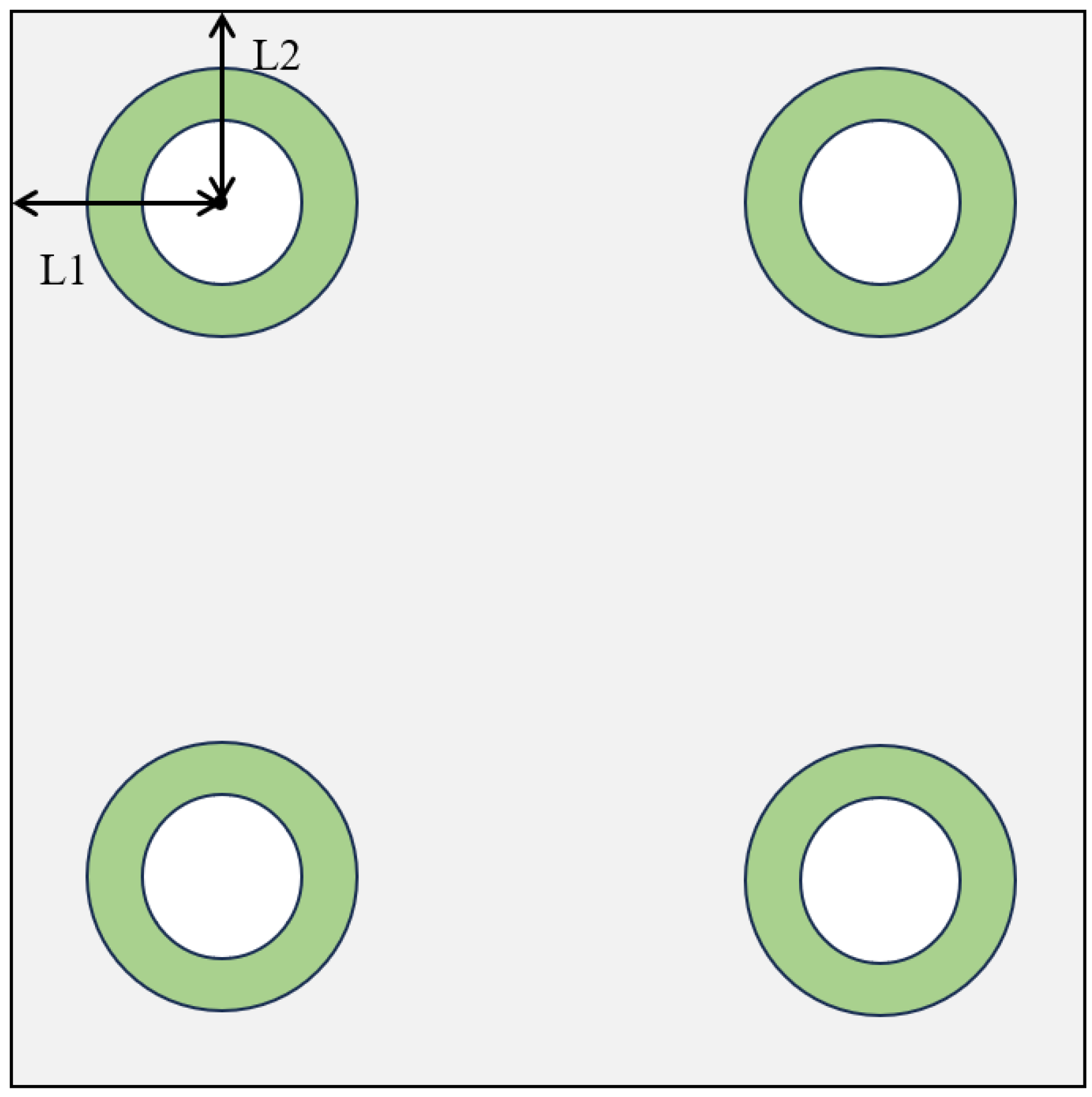
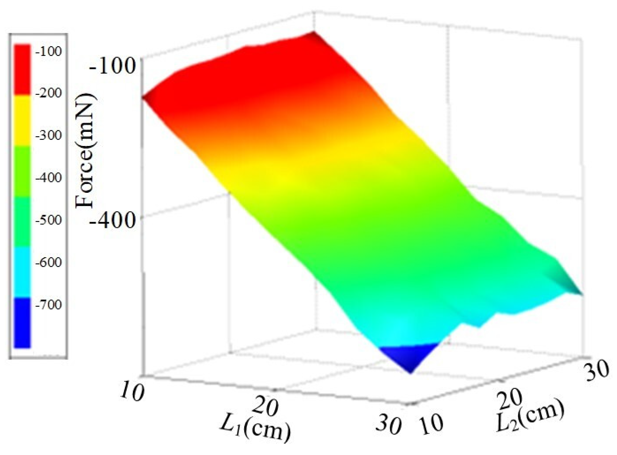
4.1. Layout Arrangement

The arrangement and layout of energized solenoids also affect the magnitude of the electromagnetic force/torque. The front view schematic of the docking plane, which illustrates the distances L1 and L2 between the energized solenoids and the edge of the platform, is shown in Figure 5. By varying L1 and L2, the variations in the electromagnetic force/torque are analyzed. The results are shown in Figure 6 and Figure 7, respectively. During the simulation analysis of the electromagnetic force/torque, the current excitation is selected as the excitation source. Due to the limited power of the power sources on CubeSats and the current-carrying capacity of the wires, onboard components typically require a power consumption of less than 25 W [32,33]. To keep the power consumption within a reasonable range, the current in the coil is set to a constant 1 A, and the current excitation is set to 2000 ampere-turns. Under these conditions, the power is 24 W, which can generate sufficient electromagnetic force.
As can be seen from Figure 7, the electromagnetic force exhibits a decreasing trend with the increase of L1. When L1 = 10 cm and L2 ranges from 10 to 30 cm, the electromagnetic force reaches its maximum value. As shown in Figure 6, the electromagnetic torque increases with the increase of L1 and the decrease of L2. The electromagnetic torque reaches its maximum value when L1 = 30 cm and L2 = 10 cm. Therefore, given the fixed inner and outer diameters of the energized solenoids, the electromagnetic force and electromagnetic torque are maximized when L1 = L2 = 10 cm, that is, when the four energized solenoids are each positioned 10 cm away from the edge of the docking interface. The values of L1 and L2 reflect the position of the energized solenoid on the docking interface, and their values can affect the interaction between the energized solenoids. As in the theoretical model, parameters related to relative position, such as rAiBj, can influence the electromagnetic force and torque. By selecting the optimal positions for L1 and L2 to generate sufficient electromagnetic force and torque and incorporating them into the aforementioned attitude control dynamics equations, a theoretical foundation can be established for utilizing electro-magnetic interactions to regulate satellite positioning and attitude.

4.2. The Direction of Current

Since different arrangements of magnetic poles yield varying electromagnetic forces, this study has designed the following four layout configurations in order to achieve the maximum electromagnetic force. The distinctions among these configurations lie in the arrangements of magnetic poles. In Layout I, all energized solenoids on the docking plane of the mother-satellite are S-poles, while those on the subsatellite are N-poles. In Layout II, the polarities are aligned in the X-direction but opposed in the Y-direction. Layout III features alternating polarities between adjacent solenoids. In Layout IV, the polarities are opposed in the X-direction but aligned in the Y-direction. In each layout, the polarities of corresponding solenoids on the subsatellite and mother-satellite are designed to be opposite, ensuring magnetic attraction for docking purposes. The subsequent analysis is based on the simulation results.
In Layout I, the energized solenoids on the docking plane of the mother-satellite are configured to become the South (S) pole by passing current in the same direction. Conversely, the energized solenoids on the docking plane of the subsatellite are configured to become the North (N) pole by passing current in the opposite direction to that of the mother-satellite, as illustrated in the figure. The variation of the electromagnetic force within the range of 0–500 mm during the docking process is shown in Figure 8.
In Layout II, the polarities are aligned in the X-direction but opposed in the Y-direction, as illustrated in Figure 9. It can be observed from the figure that the electromagnetic force generated by the energized solenoids is significantly lower than that in Layout I. Analysis reveals that most of the magnetic field lines emanating from the north pole close with the nearest oppositely polarized energized solenoid, resulting in a reduced magnetic flux density in the far field. Consequently, the attenuation of the electromagnetic field leads to a decrease in the electromagnetic force.
In Layout III, the polarity of each energized solenoid is opposite to that of its two adjacent solenoids, as illustrated in Figure 10. Analysis of Figure 10 reveals that the trend of the electromagnetic force in this configuration is the most detrimental to the operation of the electromagnetic attraction separation unit. Although the magnitude of the electromagnetic force is sufficient to adjust the attitude of the subsatellite when the distance between the subsatellite and the mother-satellite is close (<10 cm), facilitating the alignment of the subsatellite around the Z-axis with the docking plane of the mother-satellite, the force becomes significantly weaker when the distance exceeds 15 cm. This is due to the magnetic flux being concentrated within the near-field of each energized solenoid. As a result, beyond 20 cm, the electromagnetic force is too weak to enable the subsatellite to approach the docking plane of the mother-satellite solely through electromagnetic attraction.
In Layout IV, the polarities are opposed in the X-direction but aligned in the Y-direction, as illustrated in Figure 11. It can be observed from the figure that the results obtained from this configuration are similar to those of Layout II. The trend of the electromagnetic force is related to the nearest opposite polarity magnetic poles.
When the four layout arrangements are compared, a clearer understanding of the working mechanism of the electromagnetic attraction separation unit can be achieved. The curves of electromagnetic force are essentially exponential in nature. Within the range of close proximity and high magnetic flux density, the electromagnetic forces of all four layout arrangements are relatively strong. However, noticeable differences begin to emerge beyond 10 cm from the outer edge. Through comparative simulation analysis, it is evident that the electromagnetic force generated by Layout I is significantly more advantageous for the operation of the electromagnetic attraction separation unit than the other three layout arrangements.

5. Simulation and Experimental Research

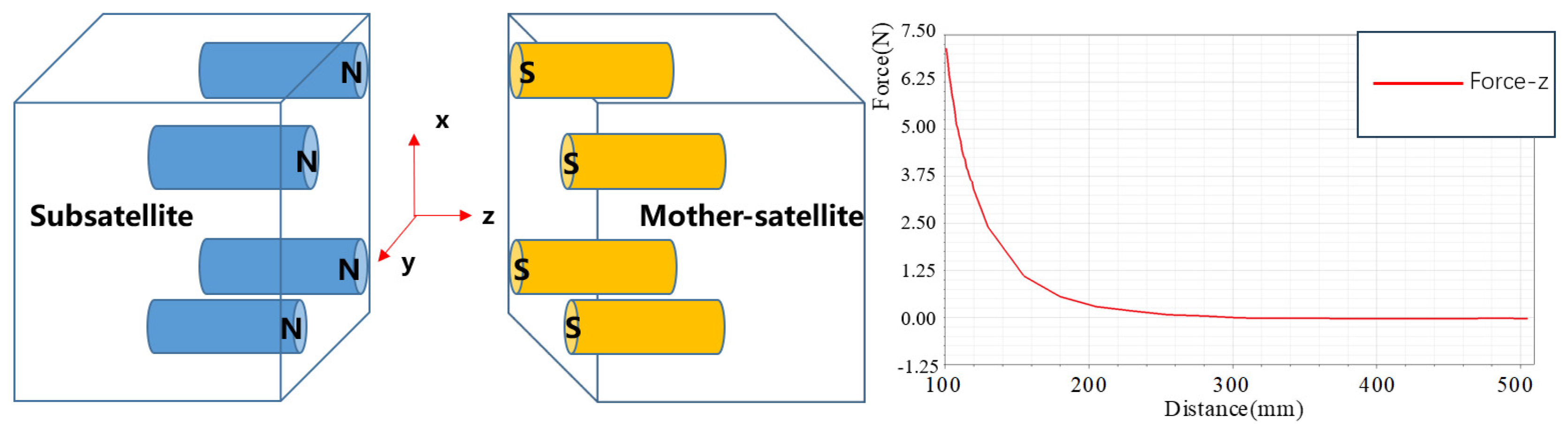
5.1. Simulation Analysis of Electromagnetic Attraction Separation Unit

The electromagnetic force/torque exhibits a complex, nonlinear coupling with the relative distance and attitude between the subsatellite and the mother-satellite. Therefore, in the dynamics simulation, as both the position and orientation of the subsatellite continuously change, the electromagnetic force/torque used to correct the subsatellite’s position and orientation also varies correspondingly.
The docking plane of the mother-satellite is assumed to be a model of the same size as the subsatellite. The energized solenoids are simplified, and the Z-axis is defined as the docking axis for the satellites. Given that most existing electromagnetic docking operations occur at distances below 500 mm [20,23], this study sets the initial distance at 500 mm (Z-axis) to provide sufficient maneuvering space for the subsatellite while keeping it within the range of electromagnetic force influence. In actual orbital scenarios, relative stability at this initial distance can be achieved through methods like orbit design and propulsion system adjustments. Figure 12 illustrates the schematic diagram of the energized solenoids with pose deviations and the ADAMS dynamic model. A fixed coordinate system is established at the initial position of the subsatellite, with initial deviations of 4° in both the roll and pitch angles between the subsatellite and mother-satellite. The initial velocities and angular velocities of both satellites are set to zero.
The kinematic and dynamic processes of the subsatellite under the action of electromagnetic force and electromagnetic torque are illustrated in Figure 13, Figure 14 and Figure 15. As shown in the figures, the relative velocity of the subsatellite increases from 0 mm/s to 6.18 mm/s. During the interval from 0 to 110 s, the electromagnetic forces and torques are relatively small, resulting in a slow reduction in the distance between the two satellites and gradual increases in velocity, accompanied by minimal adjustments to the angular deviations. After approximately 110 s, the electromagnetic force and torque begin to increase significantly, leading to noticeable changes in velocity and angular velocity. At this stage, the device starts utilizing electromagnetic torques to adjust the roll and pitch angles. Contact between the subsatellite and the mother-satellite occurs at 138 s, during which collision-induced oscillations appear in the velocity curves. This is due to the relative sliding between the top of the docking rod and the docking cone surface. The system continues to correct the angular deviations in pitch and roll through the interaction of the docking rod and cone. By approximately 150 s, the electromagnetic attraction separation mechanism completes its operation, and the two satellites continue to move as a combined assembly. In total, the roll and pitch angle errors are adjusted by 4°, with the electromagnetic force and torque contributing to a pitch angle adjustment of only 1°. The reason for this is likely the partial cancellation and weakening of the magnetic field generated by the energized solenoids in the pitch direction, resulting in a reduced electromagnetic torque and diminished attitude adjustment capability in that direction.
The simulation results indicate that the electromagnetic attraction separation unit possesses a docking range of at least 500 mm and an attitude adjustment capability with an error of no more than 4°, which preliminarily meets the design objectives. However, due to the strong coupling nonlinearity between electromagnetic forces/torques and the position and orientation, and considering that simulations inherently possess certain inaccuracies, it is challenging to obtain precise values of electromagnetic forces/torques through simulation alone when the subsatellite undergoes arbitrary attitude changes. Therefore, the attitude adjustment function of the actual electromagnetic attraction separation unit must be further verified through experiments that simulate a microgravity environment.

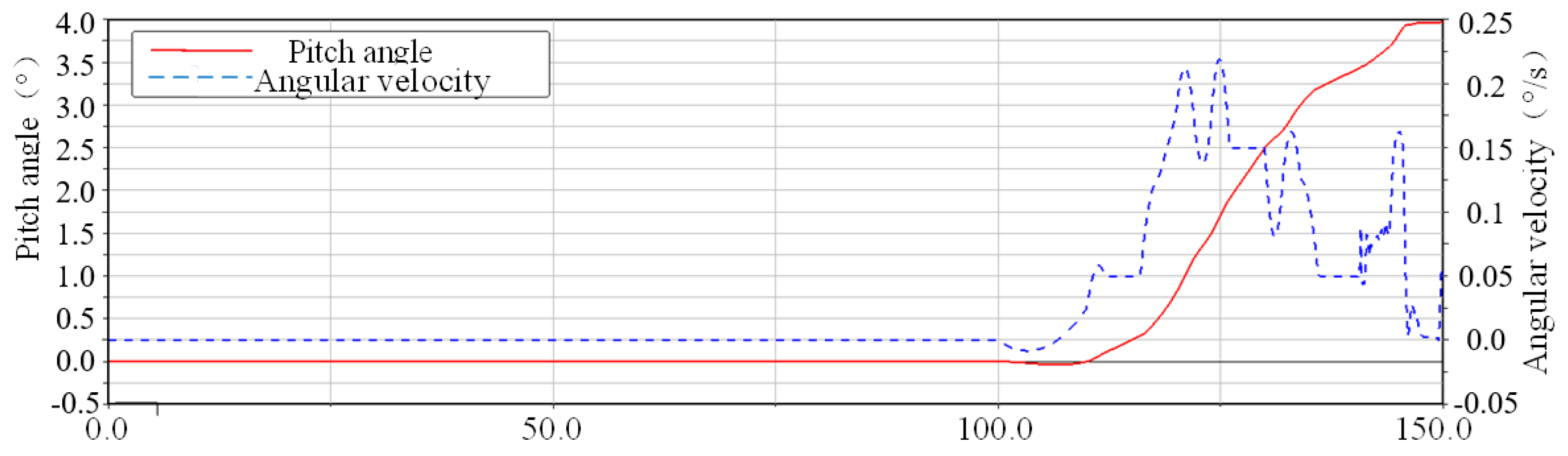
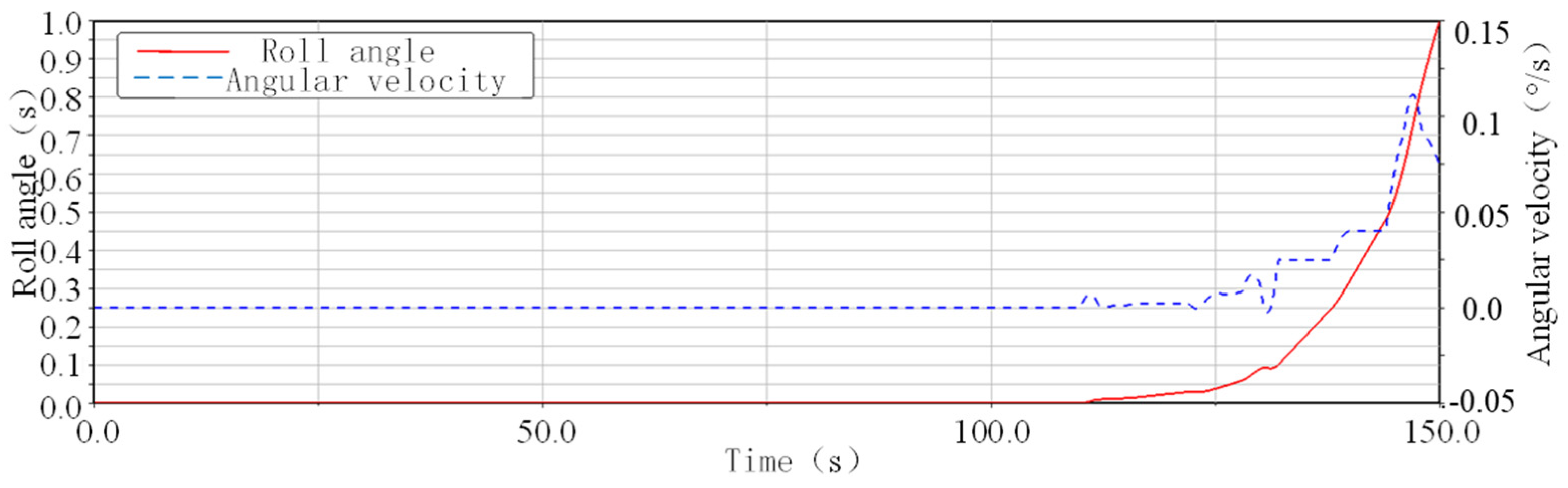
5.2. Analysis of the Impact of Electromagnetic Fields

Based on the spatial arrangement of the four energized solenoids on the docking platforms of the subsatellite and the mother-satellite, a magnetometer was employed to measure the magnetic flux density at the centers and along the lateral directions of the energized solenoids. The experimental setup is illustrated in Figure 16.
Based on the installation positions of the energized solenoids, the distances from their centers and both sides to the interior of the mechanism range from 0 to 200 mm. The primary range within which magnetic field interference occurs also falls within this interval. Beyond 200 mm, the magnetic flux density decays rapidly with increasing spatial distance. The experimental results and theoretical calculations following the selection of the path are depicted in Figure 17.
As can be inferred from the figure, the magnetic field influence generated in the radial direction at the center and on both sides of the installation position does not exhibit a simple monotonic relationship. Moreover, the magnetic fields from multiple electromagnets are mutually coupled and interact. According to experimental results, the maximum magnetic induction intensity near S1 = 50 mm is approximately 23 mT, compared to the theoretical value of 25 mT, resulting in an error of 8%. The theoretical curve shows a trend change occurring up to 5 mm earlier in position than the measured value. The discrepancy may arise from experimental distance measurement errors, installation position inaccuracies, and probe-related issues. For the magnetic field influence generated in the axial direction at the center and on both sides of the installation position, the magnetic flux density demonstrates a symmetric relationship and reaches its maximum value of approximately 10 mT near S2 = 100 mm, consistent with the theoretical value. The theoretical results align with the experimental trends, with errors within 20%. This phenomenon can be attributed to differences in the solenoid core material, environmental interference, and instrumental errors.
Considering that the maximum voltage of the energized solenoid is 24 V, and the power supply used in this experiment is a Direct Current (DC) power supply with a voltage of 22.2 V, the power consumption of the energized solenoid is constrained. Additionally, since the energized solenoid employs a DC power supply, the generated magnetic field is a low-frequency magnetic field, which does not produce high-frequency magnetic interference. Based on engineering experience, the low-frequency magnetic field generated in this study has minimal interference with electronic components. Taking into account the spatial arrangement of the energized solenoids on the docking plane, it can be concluded that there is no need to establish additional magnetic shielding mechanisms specifically for the electromagnetic attraction separation unit. However, certain protective measures can be implemented for electronic components in the surrounding space susceptible to interference.

5.3. Electromagnetic Attraction Separation Unit Captive Separation Test

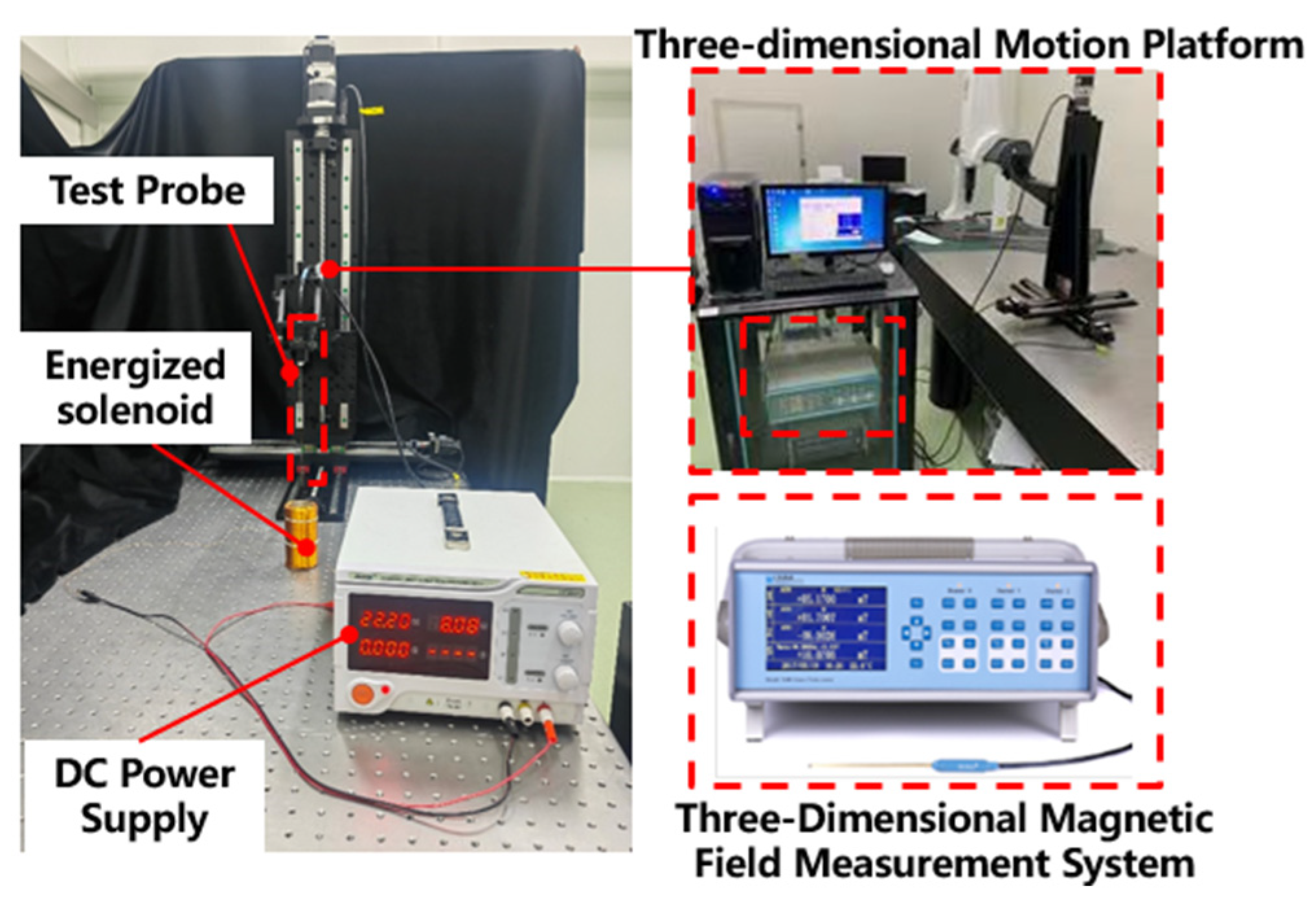
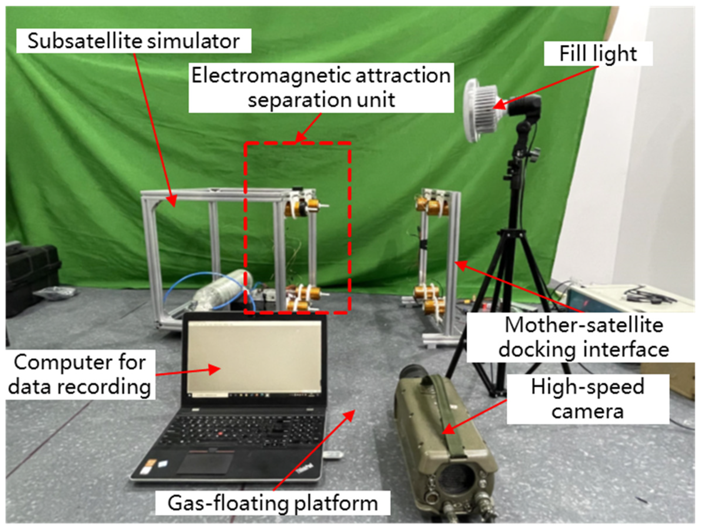
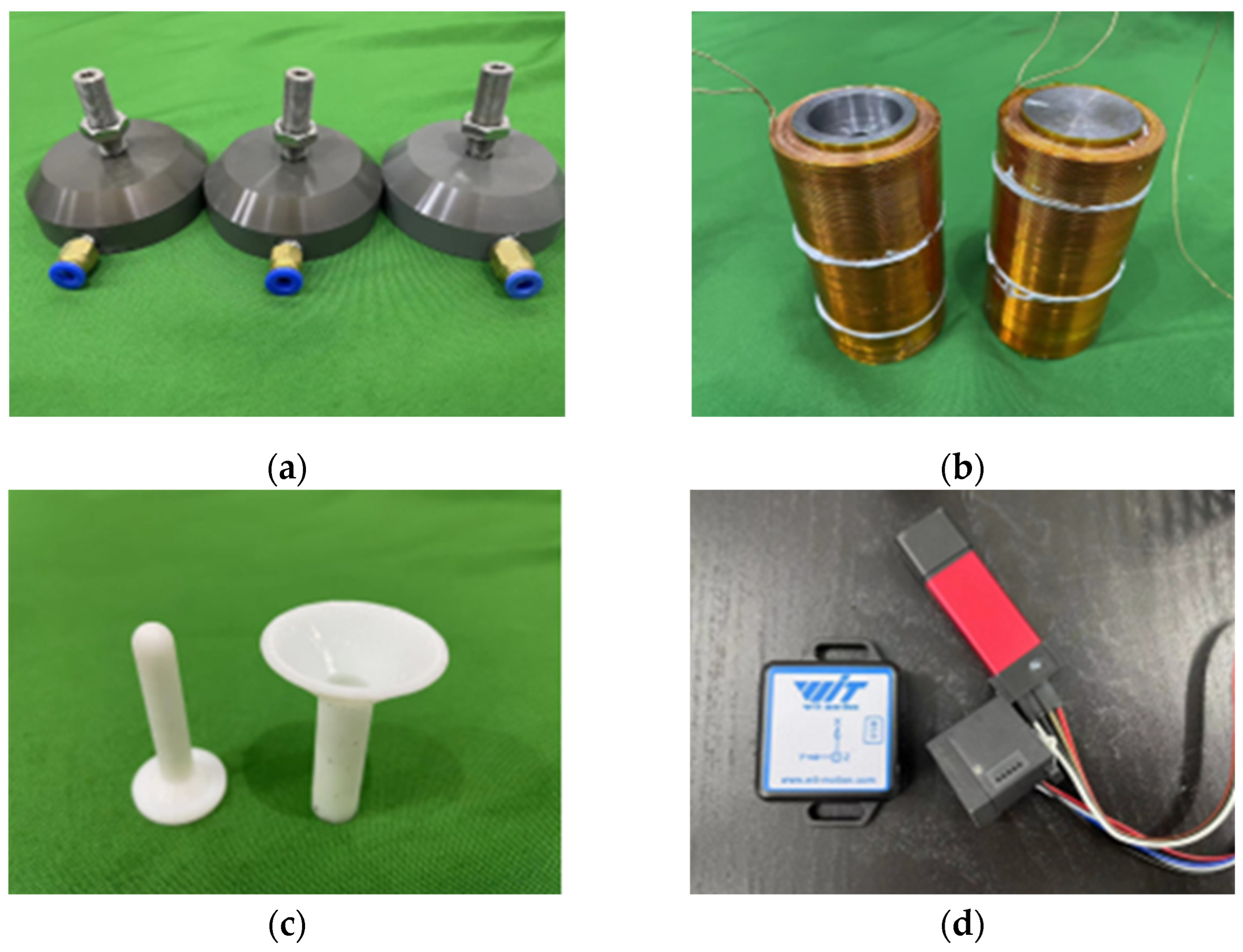
5.3.1. Composition of the Testing System

The experimental system comprises a subsatellite simulator, a mother-satellite simulator, a gas-floating platform, a triaxial accelerometer (attitude sensor), a laser displacement sensor, a high-speed camera, and a high-pressure gas cylinder, as shown in Figure 18, with the individual components depicted in Figure 19. The subsatellite and mother-satellite simulators achieve levitation on the gas-floating platform by expelling gas downward through gas jets, overcoming gravitational forces with an average clearance between the suspended body and the gas-floating platform of 5 μm. The simulators are capable of Three-Degrees-of-Freedom (3-DOF) motion on the platform, thereby emulating a frictionless environment akin to that in space. Data from the high-speed camera, accelerometer, and laser displacement sensor are acquired via a computer to facilitate the analysis of the system’s dynamic behavior. The experimental system parameters are shown in Table 1, where the solenoid core material is DT4 electromagnetic pure iron.

5.3.2. Testing Procedure

The feasibility of electromagnetic attraction and repulsion forces for docking and separation of the subsatellite and the mother-satellite, as well as the impact on the subsatellite’s attitude following successful separation, are verified through experimental methods. This provides a prerequisite and data foundation for subsequent research and design. To elucidate the relationship between design parameters and design conditions, validation of the electromagnetic force model and three-degrees-of-freedom docking process experiments under various working conditions for the subsatellite and mother-satellite have been conducted. The experimental procedure is as follows:
(1) The subsatellite simulator is moved to a specified distance according to the experimental requirements. The attitude sensor is used to read the angular deviation of the subsatellite simulator along the Z-axis, and its value is adjusted based on the experimental parameters.
(2) The gas cylinder valve is opened, placing both the subsatellite simulator and the mother-satellite simulator in a state of levitation.
(3) The power switch is activated, initiating the power supply from the lithium battery, which facilitates the docking of the subsatellite simulator and the mother-satellite simulator.
(4) After the docking, data from the attitude sensors and laser displacement sensors during the docking process are acquired.
(5) The experimental parameters are adjusted using the control variable method, and the aforementioned steps are repeated until all variables have been systematically varied.
(6) The experiment is concluded, and the results are processed and analyzed to interpret the observed phenomena.

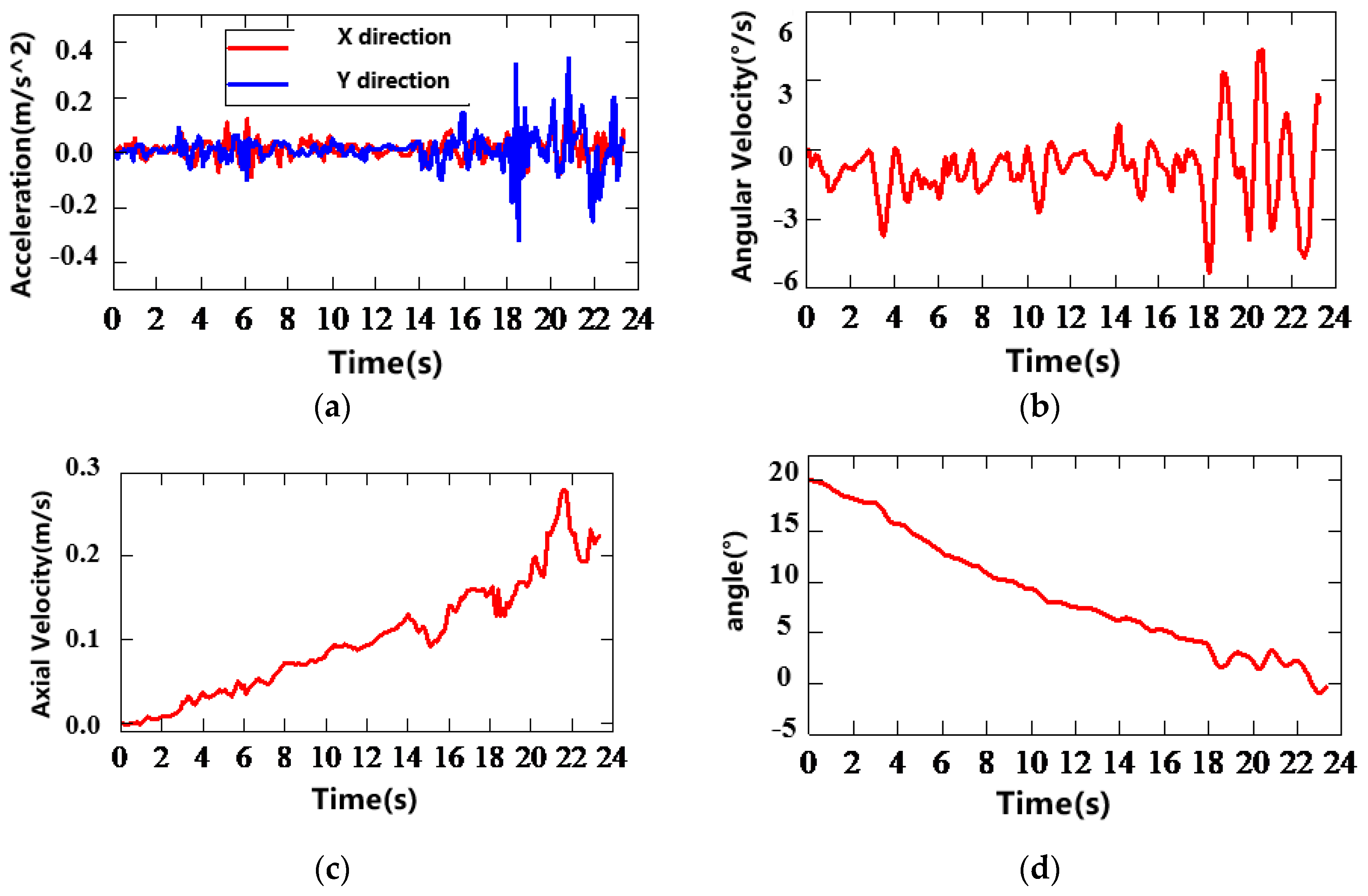
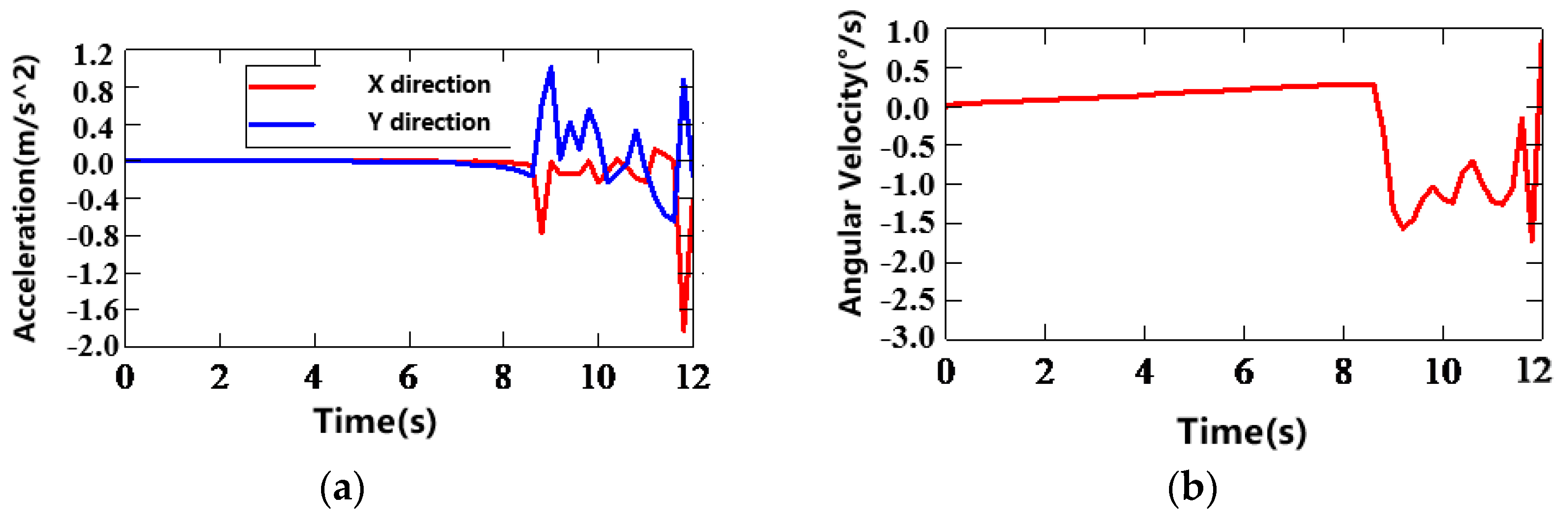
5.3.3. Test Results and Analysis

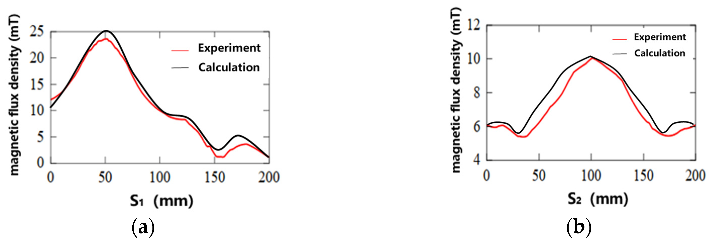
  • Experimental Validation of the Electromagnetic Force Model
For the highly nonlinear and complex model of the electromagnetic adsorption and separation assembly discussed in this paper, it is essential to validate the electromagnetic force model of the electromagnetic field finite element simulation software through experimental methods. We can ensure that the coils have the correct polarity in each test and maintain a consistent voltage level by incorporating a voltage-stabilizing module. This is crucial because voltage differences between two energized solenoids can lead to magnetic field mismatches, reducing docking efficiency and potentially causing unwanted attractions with nearby conductive components or other solenoids. The docking performance is optimal when the solenoids operate at the same voltage.
The mother-satellite was positioned in a stationary state, while the subsatellite was placed on its gas bearings to simulate free movement in space. The measurement of the electromagnetic force has been conducted using a digital force gauge. By measuring the forces at different positions with a separation of 100 mm during full docking, the relationship between the electromagnetic force and distance has been established. A portion of the experimental data and the theoretical data is presented in Table 2.
By comparing the theoretical calculations with experimental measurements, it is evident that the theoretical values are generally higher, with deviations within 11.9%. This discrepancy arises from experimental losses, such as multiphysics coupling effects (e.g., eddy currents, hysteresis, and thermal radiation). As the two satellites move apart, measurement accuracy becomes the dominant source of error.
2.
Analysis of Test Results and Phenomena
To simulate the frictionless environment in space and the different attitude error conditions of the subsatellite in space, multiple sets of experiments were conducted on the air-floating platform. Considering the influence of different polarities generated by different layouts of the energized solenoids, four sets of experiments with different layout conditions and one set of subsatellite separation experiments were set up.
In the docking experiment, the initial velocities, accelerations, and angular velocities of the two satellites were all zero, with the deviation angle varying between 0° and 30° according to the requirements of each experiment. Docking is considered successful if, at the end of the process, the velocity is less than 0.25 m/s and the deviation angle is within ±1.5°. Additionally, if no significant displacement occurred within 10 s during the experiment, or if the two satellites moved in opposite directions for over 10 s after colliding, the experiment can be deemed a failure.
In the separation experiment, the two satellites started in a docked state with no deviation angle, and a pose deviation of less than 5° is considered an acceptable separation error. The target velocity for separation is greater than 0.3 m/s.
The first set of experiments was conducted based on Layout I, and the experimental results are shown in Table 3. All the energized solenoid poles of the docking end of the subsatellite are S poles, and all the energized solenoid poles of the docking plane end of the mothership are N poles. The subsatellite started docking from a distance of 500 mm, the power supply was turned on, and the gas bottle switch was opened. In the linear docking (with a deviation angle of 0°), the entire motion process only took 24.3 s, and repeated experiments were all successful.
In the 500 mm, 20° and 600 mm, 25° working conditions, successful docking was followed by separation. This is due to the initial docking axial velocity and deviation angle exceeding the expected standards, with velocities over 0.4 m/s causing violent collisions after docking. This indicates that controlling the current magnitude to adjust docking speed can enhance success rates in electromagnetic docking. In the 500 mm, 20° and 600 mm, 30° working conditions, direct collisions led to failures. This occurred because the pose differences were too large, causing the docking rod to overshoot the docking cone’s plane during angle adjustment, resulting in overcorrection and collisions without guidance. This phenomenon became more frequent when θ ≥ 30°.
When θ ≥ 30°, the capture and docking of the electromagnetic attraction separation unit gradually becomes difficult. Although the docking is still successful in most experimental results, sometimes the angular momentum of the subsatellite may cause the docking rod to pass over the docking cone plane, leading to collisions and resulting in docking failure.
In the case where the docking extreme angle θ = 30°, the docking time is 32.9 s. If the angle θ exceeds the tolerance range, the docking rod will attempt to correct its pose deviation, but an overshoot will occur. When the docking rod realigns, the distance between the parent and subsatellites is no longer sufficient to complete the coupling of the docking rod and the docking cone, resulting in docking failure. This situation applies to all angles outside the tolerance range.
The kinematic analysis was conducted using the third result of the working condition with an initial distance of 500 mm and an angular deviation of 20°, as shown in Figure 20. The results are consistent with the trend of the simulation analysis. When the simulated subsatellite is at a greater distance from the simulated mother-satellite, both its acceleration and angular velocity are relatively small. After 16 s, the electromagnetic force increases significantly due to the reduced relative distance, leading to a marked increase in axial velocity. Around 21 s, there is a significant change in acceleration and angular velocity, accompanied by oscillations. This is due to the collision between the docking rod and the docking cone surface. After the collision, the two models successfully redock and eliminate the angular deviation due to the strong electromagnetic attraction force. The observed trends align with the simulation predictions: the angular velocity initially changes slowly, followed by significant variations in velocity and angular velocity as the distance decreases. After contact between the two satellites, oscillations in velocity and angular velocity occur, eventually stabilizing.
The second set of experiments was conducted based on Layout II, and the experimental results are shown in Table 4. It is known from the simulation analysis of this layout method that the electromagnetic attraction generated by this layout is relatively weak. Therefore, this experiment was carried out to verify whether or not this layout could achieve better attitude correction.
When the distance between the mother-satellite and subsatellite was 500 mm, the subsatellite did not move within 10 s after the power supply and gas cylinder were turned on, so docking failed. Thus, this experiment started with a distance of 400 mm between the mother-satellite and subsatellite. In the linear docking (with a deviation angle of 0°), the entire docking process took 12 s. Although the docking speed decreased, the adjustable range of the Z-axis angle remained large, and the adjustment speed was fast. At 400 mm and 25°, one test showed post-docking separation, with an initial docking speed of about 0.35 m/s. At 400 mm and 20°, the subsatellite collided with the mother-satellite without proper alignment due to overshooting the docking cone plane during angle adjustment. At 400 mm and 30°, during pose adjustment, the north poles of the two sides faced each other, creating a strong repulsive force that pushed the subsatellite out of the docking system’s adjustment range. When θ ≥ ±30°, which is a large angular deviation, although electromagnetic forces and torques can adjust the attitude of the subsatellite, the rotation direction is opposite to that required for docking. In this scenario, the same poles of the energized solenoids on the subsatellite and mother-satellite face each other, generating repulsive forces. This increases angular velocity and causes the satellites to move apart, preventing successful docking. Therefore, Layout II is not suitable for the docking of mother-satellite and subsatellite, but its advantage of faster angle change can be utilized in pulse attitude correction in control. Figure 21 shows the kinematic curve of the subsatellite’s docking rod being ejected, realigned, and successfully docked under the condition of 400 mm and 5°. After docking, the axial velocity became zero, and the deviation angle was only 1°.
Based on Layout III, the third group of experiments was carried out, and the experimental results are shown in Table 5. The layout of alternating the north pole/south pole on the mother and subsatellites generates a relatively small electromagnetic force. When the distance between the mother and subsatellites is greater than 400 mm, the subsatellite does not show any obvious positive displacement signs. It is not until the initial distance is adjusted to 300 mm that the subsatellite can move. However, at this distance, if θ ≥ ±10°, it may cause the energized solenoid to be misaligned or even the same poles at both ends to align and generate repulsive force, leading to docking failure. In cases where misalignment occurred, the subsatellite exited the electromagnetic influence range before contact with the mother-satellite and remained stationary for over 10 s, which was classified as a docking failure.
In this group of experiments, a special phenomenon occurred. The curves of acceleration and angular velocity changes when the distance was 300 mm and the angle was 10° are shown in Figure 22. The subsatellite did not show a clear tendency to correct its attitude when the distance was greater than 100 mm. It only corrected its attitude when the distance was relatively close. After the collision, the docking failed. The reason for this is because the magnetic field lines of this layout with the same polarity on the diagonal are only distributed at close range. Therefore, the separation process of the mother and subsatellite simulation components can use this characteristic to reduce the influence of electromagnetic torque on the attitude of the subsatellite.
Based on Layout IV, the fourth set of experiments was conducted, and the results are shown in Table 6. In the simulation analysis, the trend of electromagnetic force and torque changes in Layout II and Layout IV are similar. On the three-degrees-of-freedom air-bearing table, the electromagnetic attraction separation unit in this layout direction can successfully complete docking within 20 degrees. However, in a six-degrees-of-freedom space, it can be anticipated that similar interferences as in Layout II will still exist. Therefore, Layout IV is also suitable for attitude correction. Its attitude changes must be carefully controlled to prevent the alignment of solenoids with the same polarity, which could cause the subsatellite to spin and result in docking failure.
Based on the wiring of the third group in the layout, the direction of the current flowing through the energized solenoid was changed so that the solenoids at the subsatellite end and the mother-satellite end had different polarities. Utilizing the characteristics of the third group that did not significantly show a tendency to correct the attitude, a separation test of the subsatellite and mother-satellite simulation pieces was conducted. The trends of acceleration, angular velocity, velocity, and angle changes obtained from the test are shown in Figure 23. It can be seen from the figure that, at the moment of energization, the subsatellite experienced an axial acceleration of 0.74 m/s2 in the Y direction, while the acceleration in the X direction remained relatively small. As the distance between the subsatellite and the mother-satellite increased, the acceleration and angular velocity gradually stabilized. The electromagnetic force/torque had become so weak that it hardly affected the subsatellite simulation piece. At this time, the separation velocity of the satellite was approximately 0.303 m/s and the attitude deviation in the Z-axis direction was −4.21°. After the motion stabilized, sufficient separation velocity has been achieved, and the deviation angle remained below 5°, meeting the separation requirements.
Upon synthesizing all the experimental outcomes, it is evident that the adaptive attitude adjustment docking range of the electromagnetic attraction component is a semi-conical region with an apex angle of 30°. The greater the deviation angle, the higher the likelihood of capture failure, and the repeatability and precision of docking are significantly diminished. This suggests that if the electromagnetic attraction separation unit is subsequently improved, for instance, by incorporating circuit control and employing paramagnetic materials as magnetic tips, there remains potential for enhancing the maximum range of adaptive attitude adjustment docking. Moreover, the maximum deviation angle is also correlated with the distance between the mother-satellite and the subsatellite, as shown in Table 7. Additionally, since minor changes in the position of the subsatellite at the onset of docking can easily result in the alignment of energized solenoids at the same location, thereby generating a repulsive force that is difficult to correct, it is imperative to carefully consider the impact of different polarity layouts produced by the energized solenoids after the current is applied.
Based on the issues encountered during the experimental process and observations of the experimental results, the factors contributing to the errors are analyzed as follows:
(1) Geometric Deviations in the Processing and Layout of Energized Solenoids
The cores and coils obtained after processing are not entirely consistent. The geometric positions of each set of energized solenoids deviate from the theoretical values when laid out. When the energized solenoids at the same position are aligned, it is found that they do not completely overlap. Moreover, the requirement for the winding is that the number of turns in the eight coils should be equal, but this may not be achieved in practice. This can lead to the generation of forces along the x-axis and moments around the y-axis, even when two energized solenoids are coaxially aligned.
(2) Position Measurement Deviations
The range of electromagnetic force is small, and its magnitude is inversely proportional to the cube of the distance, decaying rapidly with increasing distance. Accurate measurement of the relative positions of energized solenoids is crucial when measuring electromagnetic force. Within a certain range of positional errors, as the relative distance between the energized solenoids decreases, the corresponding deviations in force and torque gradually increase. Introducing optical measurement equipment in experiments can significantly improve measurement accuracy.
(3) Current Measurement Deviations
According to simulation analysis, the magnitude of electromagnetic force/torque is closely related to the ampere-turns of the current passing through the energized solenoids. The number of turns may not be consistent, and the magnitude of the current passing through is also difficult to ensure the same. In experiments, it is not easy to achieve precise measurements of the actual current value due to the loading of preset current and the inclusion of capacitors and inductors in the added voltage stabilizing module. A dedicated closed-loop current control system needs to be designed to ensure that the magnitude and direction of the current meet the requirements.
(4) Deviations in Force and Torque, Attitude, and Laser Displacement Sensor Measurements
The sensors used to measure electromagnetic force/torque, the attitude, and displacement characteristics during the docking process of the subsatellite are also sources of experimental errors. Calibration and noise filtering are required before measurement, and they are affected by the precision and range of the sensors. Especially when the electromagnetic force cannot be precisely measured after a certain distance, sensors with higher precision and sensitivity are needed to meet the requirements.

6. Conclusions

This paper, based on the in-orbit servicing technology of mother-satellite and subsatellite systems, proposes a reusable docking and separation mechanism that employs electromagnetic force/torque for large-tolerance capture, low-impact separation, and rigid locking. Through theoretical analysis and experimental tests, the following main conclusions can be drawn:
1. A reusable electromagnetic docking scheme based on screw transmission and electromagnets is proposed. The overall mechanism is divided into three components: the electromagnetic attraction separation unit, the rigid locking unit, and the transmission unit. Detailed structural designs are conducted for each component. With the objective of maximizing electromagnetic force/torque, the design is optimized in terms of mass and power consumption. This approach achieves non-consumptive, low-impact, and plume-free reusable docking and separation of mother-satellite and subsatellite systems.
2. Four electromagnet layout configurations are proposed. Dynamic simulation analyses are performed on the electromagnetic attraction separation unit and the rigid locking unit, verifying that the subsatellite can be successfully captured and locked even with certain pose errors. After the motor is powered off, the locking state can be maintained by the preloading force applied through disc springs. Docking and separation experiments on the mother-satellite and subsatellite systems are conducted, revealing that the adaptive attitude adjustment and docking range of the electromagnetic attraction separation unit is a semi-cone with an angle of 30°. The motion trends of the subsatellite are consistent with the simulation results, and different layouts of the electromagnetic attraction separation unit exhibit distinct characteristics.
3. In this paper, optimization is only conducted for the four-point layout of the energized solenoids, resulting in a relatively singular form. Future work will focus on exploring different configurations and shapes to meet engineering requirements. Additionally, research will be conducted on the multidimensional flexible electromagnetic docking control problem of energized solenoids to configure the docking trajectory reasonably.
4. This study includes a comparative analysis of theoretical calculations and experimental data, with current electromagnetic force and torque calculation errors within 11.9%. In the future, methods such as neural networks will be employed to integrate both theoretical and experimental data, further improving the predictive accuracy of the electromagnetic force and torque models to meet engineering requirements.

Author Contributions

Conceptualization, X.Y. and C.L.; methodology, H.Y.; software, L.Z.; validation, Z.Z., C.H. and M.L.; formal analysis, T.H. and Y.W.; investigation, Y.Z. (Yuhao Zhang); resources, Y.Z. (Yong Zhao); data curation, L.Z. and M.L.; writing—original draft preparation, X.Y. and C.L.; writing—review and editing, Z.Z., C.H. and T.H.; visualization, Y.Z. (Yuhao Zhang) and Y.W.; supervision, H.Y.; project administration, Y.Z. (Yong Zhao); funding acquisition, H.Y. and Y.Z. (Yong Zhao). All authors have read and agreed to the published version of the manuscript.

Funding

This work was funded by the Foundation of National Key Laboratory of Aerospace Mechanism, China (Grant No. 2024ASH-ZY05), the China Postdoctoral Science Foundation (Grant No. 2024M764201), the Heilongjiang Postdoctoral Science Foundation (Grant No. LBH-Z24184), the National Natural Science Foundation of China (Grant No. 52405257), the Postdoctoral Fellowship Program (Grade B) of China Postdoctoral Science Foundation (Grant No. GZB20240955), the Natural Science Foundation of Heilongjiang Province, China (Grant No. LH2024E029), and the Foundation of Chinese State Key Laboratory of Robotics and Systems (Grant No. SKLRS202413B).

Data Availability Statement

Data are contained within the article.

Acknowledgments

The authors would like to thank the editors, academic editor, and the reviewers for their valuable comments and constructive suggestions that helped to improve the paper significantly.

Conflicts of Interest

Author Lili Zhang was employed by the company Harbin Space Star Data System Technology Co., Ltd. The remaining authors declare that the research was conducted in the absence of any commercial or financial relationships that could be construed as a potential conflict of interest.

Abbreviations

The following abbreviations are used in this manuscript:
HPRHeading, Pitch, Roll
DCDirect Current

References

  1. Orozco, M.L.; Giraldo, B.S. Attitude Determination and Control in Small Satellites: A Review. IEEE J. Miniatur. Air Space Syst. 2024, 5, 182–186. [Google Scholar] [CrossRef]
  2. Fevgas, G.; Lagkas, T.; Sarigiannidis, P.; Argyriou, V. Advances in Remote Sensing and Propulsion Systems for Earth Observation Nanosatellites. Future Internet 2025, 17, 16. [Google Scholar] [CrossRef]
  3. Rosero-Montalvo, P.D.; Priest, J.C.P. CubeSat Imaging Payload Design for Environmental Monitoring of Greenland. Electronics 2025, 14, 18. [Google Scholar] [CrossRef]
  4. Quarta, A.A. Preliminary Trajectory Analysis of CubeSats with Electric Thrusters in Nodal Flyby Missions for Asteroid Exploration. Remote Sens. 2025, 17, 513. [Google Scholar] [CrossRef]
  5. Battistini, S.; De Angelis, G.; Pontani, M.; Graziani, F. An Iterative Guidance and Navigation Algorithm for Orbit Rendezvous of Cooperating CubeSats. Appl. Sci. 2022, 12, 9250. [Google Scholar] [CrossRef]
  6. Oumer, A.M.; Kim, D.-K. Real-Time Fuel Optimization and Guidance for Spacecraft Rendezvous and Docking. Aerospace 2022, 9, 276. [Google Scholar] [CrossRef]
  7. El Ghali, A.; Zhu, Z.H. An introductory review of swarm technology for spacecraft on-orbit servicing. Int. J. Mech. Syst. Dyn. 2024, 4, 3–21. [Google Scholar]
  8. Underwood, C.; Pellegrino, S.; Lappas, J.V.; Bridges, C.; Baker, J. Using CubeSat/micro-satellite technology to demonstrate the Autonomous Assembly of a Reconfigurable Space Telescope. Acta Astronaut. 2015, 114, 112–122. [Google Scholar] [CrossRef]
  9. Fabrizio, S. Tracking Model Predictive Control for Docking Maneuvers of a CubeSat with a Big Spacecraft. Aerospace 2021, 8, 197. [Google Scholar] [CrossRef]
  10. Xiangtian, Z.; Shijie, Z. Adaptive saturated control for spacecraft rendezvous and docking under motion constraints. Aerosp. Sci. Technol. 2021, 114, 106739. [Google Scholar]
  11. Deng, S.; Li, K.; Cai, H.; Duan, J.; Zhi, J.; Wang, Y. Design and Analysis of Non-cooperative Target Space Docking Mechanism. In Proceedings of the 2022 Chinese Intelligent Systems Conference, Beijing, China, 15–16 October 2022; Springer: Singapore, 2022. [Google Scholar]
  12. Yue, H.; Yang, Y.; Lu, Y.; Yang, F.; Deng, Z. Research Progress of Space Non-Pyrotechnic Low-Shock Connection and Separation Technology (SNLT): A Review. Chin. J. Aeronaut. 2021, 34, 113–154. [Google Scholar] [CrossRef]
  13. Shi, K.; Liu, C.; Biggs, J.D.; Sun, Z.; Yue, X. Observer-based control for spacecraft electromagnetic docking. Aerosp. Sci. Technol. 2020, 99, 105759. [Google Scholar] [CrossRef]
  14. Branz, F.; Olivieri, L.; Sansone, F.; Francesconi, A. Miniature docking mechanism for CubeSats. Acta Astronaut. 2020, 176, 510–519. [Google Scholar] [CrossRef]
  15. Pérez-del-Pulgar, C.J.; Palomeque, A.L.; Juli, J.; Madi, M. Extensible Hook System for Rendezvous and Docking of a CubeSat Swarm. Eng. Proc. 2025, 90, 33. [Google Scholar] [CrossRef]
  16. Kong, E.M.C.; Otero, A.S.; Nolet, S.; Berkovitz, D.S.; Miller, D.W.; Sell, S.W. SPHERES as a Formation Flight Algorithm Development and Validation Testbed: Current Progress and Beyond. In Proceedings of the 2nd International Symposium on Formation Flying Missions and Technologies, Paris, France, 19–21 October 2004. [Google Scholar]
  17. Harris, T.; Forshaw, J.; Lindsay, M.; Brydon, G.; Lidtke, A.; Yarr, N. Space Situational Awareness (SSA) activities explored through the ELSA-d mission. In Proceedings of the Advanced Maui Optical and Space Surveillance Technologies Conference (AMOS), Maui, HI, USA, 8–11 October 2024. [Google Scholar]
  18. Olivieri, L.; Branz, F.; Duzzi, M.; Mantellato, R.; Grassi, G.; Sansone, F.; Francesconi, A. Technologies to Join Spacecraft Using a Tethered Electromagnetic Probe. In Proceedings of the XXIV International Conference of the Italian Association of Aeronautics and Astronautics, Palermo-Enna, Italy, 18–22 September 2017. [Google Scholar]
  19. Foust, R.C.; Lupu, E.S.; Nakka, Y.K.; Chung, S.-J.; Hadaegh, F.Y. Ultra-Soft Electromagnetic Docking with Applications to In-Orbit Assembly. In Proceedings of the 69th International Astronautical Congress (IAC), Bremen, Germany, 1–5 October 2018. [Google Scholar]
  20. Duzzi, M.; Casagrande, R.; Mazzucato, M.; Moro, L.; Francesconiet, A. Electromagnetic Position and Attitude Control for PACMAN Experiment. In Proceedings of the 10th International ESA Conference on Guidance, Navigation & Control Systems, Salzburg, Austria, 5–9 June 2017. [Google Scholar]
  21. Ruan, G.; Wu, L.; Wang, Y.; Wang, B.; Han, R. Micro- and Nanosatellite Sensorless Electromagnetic Docking Control Based on the High-Frequency Injection Method. Aerospace 2023, 10, 547. [Google Scholar] [CrossRef]
  22. Ruan, G.; Wu, L.; Han, R.; Wang, B. Design of Electromagnetic Docking Device for Micro–Nanosatellite. Adv. Astronaut. Sci. Technol. 2022, 5, 341–350. [Google Scholar] [CrossRef]
  23. Ruan, G.; Wu, L.; Wang, B.; Wang, Y.; Han, R. A solution using only electromagnetic coils for relative pose control in satellite docking. Chin. J. Aeronaut. 2024, 37, 258–281. [Google Scholar] [CrossRef]
  24. Zhang, Y.W.; Chen, P.L. Self-Alignment Capability Analysis and Self-Attraction Dipole Solution of Spacecraft Electromagnetic Docking. AIAA J. 2023, 61, 3247–3256. [Google Scholar] [CrossRef]
  25. Vilvanathan, V.; Raj, A.T.; Vance, L.D.; Eniko, E. Sequential Control of Electromagnets for CubeSat Docking Attitude Alignment. In Proceedings of the ASCEND 2023 Conference, Las Vegas, NV, USA, 25–28 July 2023. [Google Scholar]
  26. Liu, C.; Yue, X.; Zhang, J.; Shi, K. Active Disturbance Rejection Control for Delayed Electromagnetic Docking of Spacecraft in Elliptical Orbits. IEEE Trans. Aerosp. Electron. Syst. 2021, 58, 2257–2268. [Google Scholar] [CrossRef]
  27. Lijian, W.; Guangzheng, R.; Runqi, H.; Bo, W.; Yaobing, W. Relative Roll Control of Satellite Docking Using Electromagnetic Coils. Chin. J. Aeronaut. 2023, 36, 361–374. [Google Scholar]
  28. Wei, B.; Zhang, J.; Kong, N.; Ma, S.; Wang, B.; Han, R. Self-Docking Characteristics and Sliding Mode Control on Space Electromagnetic Docking Mechanism. Machines 2023, 11, 332. [Google Scholar] [CrossRef]
  29. Cui, Y. Mechanical System Dynamics; Science Press: Beijing, China, 2017; pp. 35–49. (In Chinese) [Google Scholar]
  30. Wertz, J.R. Spacecraft Attitude Determination and Control; Kluwer Academic Publishers: Boston, MA, USA, 1978; pp. 362–435. [Google Scholar]
  31. Jackson, J.D. Classical Electrodynamics, 3rd ed.; John Wiley & Sons: New York, NY, USA, 1998; pp. 174–225. [Google Scholar]
  32. Knap, V.; Bonvang, G.A.P.; Fagerlund, F.R.; Krøyer, S.; Nguyen, K.; Thorsager, M.; Tan, Z.-H. Extending battery life in CubeSats by charging current control utilizing a long short-term memory network for solar power predictions. J. Power Sources 2024, 618, 235164. [Google Scholar] [CrossRef]
  33. Ali, M.B.O.E.; Abbaker, A.E.M.; Elfaki, S.E.E. Modeling, Simulation, and Implementation of the Electrical Power System of Cube Satellite Using Matlab and Simulink. In Proceedings of the 2020 International Conference on Computer, Control, Electrical, and Electronic Engineering (ICCCEEE), Khartoum, Sudan, 26 February–1 March 2021. [Google Scholar]
Figure 1. Schematic diagram of the electromagnetic attraction separation unit.
Remotesensing 17 01446 g001
Figure 2. Schematic diagram of the rigid locking unit. 1—Passive end; 2—Plunger; 3—Connecting rod; 4—Screw nut; 5—Double-ended screw; 6—Bevel gear; 7—Motor.
Remotesensing 17 01446 g002
Figure 3. Schematic diagram of HPR attitude.
Remotesensing 17 01446 g003
Figure 4. Schematic diagram of magnetic dipole positions.
Remotesensing 17 01446 g004
Figure 5. The front view schematic of the docking interface.
Remotesensing 17 01446 g005
Figure 6. Electromagnetic torque of solenoids with different layout configurations.
Remotesensing 17 01446 g006
Figure 7. Electromagnetic forces of solenoids with different layout configurations.
Remotesensing 17 01446 g007
Figure 8. Electromagnetic force of Layout I.
Remotesensing 17 01446 g008
Figure 9. Electromagnetic force of Layout II.
Remotesensing 17 01446 g009
Figure 10. Electromagnetic force of Layout III.
Remotesensing 17 01446 g010
Figure 11. Electromagnetic force of Layout IV.
Remotesensing 17 01446 g011
Figure 12. Schematic diagram of the dynamic model: (a) Electromagnetic simulation model; (b) Dynamic simulation model.
Remotesensing 17 01446 g012
Figure 13. Velocity variation curve of the subsatellite.
Remotesensing 17 01446 g013
Figure 14. Variation curve of the roll angle of the subsatellite.
Remotesensing 17 01446 g014
Figure 15. Variation curve of the pitch angle of the subsatellite.
Remotesensing 17 01446 g015
Figure 16. Experimental setup for magnetic field testing.
Remotesensing 17 01446 g016
Figure 17. Magnetic flux density variation curve: (a) Radial variation curve; (b) Axial variation curve.
Remotesensing 17 01446 g017
Figure 18. Photograph of the experimental system.
Remotesensing 17 01446 g018
Figure 19. The components of the experimental setup: (a) Air bearing; (b) Energized solenoids; (c) Docking rod and cone; (d) Sensors.
Remotesensing 17 01446 g019
Figure 20. Test Results of subsatellite docking under the condition of 500 mm and 20°: (a) Acceleration variation in the X and Y directions; (b) Angular velocity variation; (c) Axial velocity variation; (d) Angular variation in the Z direction.
Remotesensing 17 01446 g020
Figure 21. Test results of subsatellite docking under the condition of 400 mm and 5°: (a) Acceleration variation in the X and Y directions; (b) Angular velocity variation; (c) Axial velocity variation; (d) Angular variation in the Z direction.
Remotesensing 17 01446 g021
Figure 22. Test results of subsatellite docking under the condition of 300 mm and 10°: (a) Acceleration variation in the X and Y directions; (b) Angular velocity variation.
Remotesensing 17 01446 g022
Figure 23. Test results of the subsatellite separation process: (a) Acceleration variation in the X and Y directions; (b) Angular velocity variation; (c) Axial velocity variation; (d) Angular variation in the Z direction.
Remotesensing 17 01446 g023
Table 1. Test system parameter.
ParameterValue
Solenoid length100 mm
Coil outer diameter55 mm
Iron core diameter40 mm
Number of turns2000 turns
Current1 A
Dimensions of docking interface500 × 500 mm
Table 2. Axial electromagnetic force generated in one-dimensional docking experiments.
NumberDistance d (mm)Electromagnetic Force F (N)Theoretical Electromagnetic Force (N)Error (%)
1212.04213.67611.9%
253.5243.8548.6%
3101.3551.53211.6%
4200.4250.47811.1%
5500.0870.09811.2%
61000.0190.0219.5%
Table 3. Test results of Layout I.
NumberExperimental ParametersTest Results
Initial Distance (mm)Eccentricity (mm)Deviation Angle θFirst TimeSecond TimeThird Time
15005Succeeded
0.1 m/s, 0°
Succeeded
0.2 m/s, 0.1°
Succeeded
0.05 m/s, 0°
25005Succeeded
0.09 m/s, −0.1°
Succeeded
0.05 m/s, 0.2°
Succeeded
0.1 m/s, 0°
3500510°Succeeded
0.18 m/s, 0.3°
Succeeded
0.21 m/s, −0.2°
Succeeded
0.08 m/s, 0.1°
4500520°EjectedCollidedSucceeded
0.23 m/s, −0.1°
5600520°Succeeded
0.18 m/s, 0°
Succeeded
0.14 m/s, 1°
Succeeded
0.06 m/s, 0.2°
6600525°Succeeded
0.16 m/s, 0.2°
EjectedSucceeded
0.21 m/s, 0.1°
7600530°CollidedSucceeded
0.2 m/s, −0.1°
Collided
Table 4. Test results of Layout II.
NumberExperimental ParametersTest Results
Initial Distance (mm)Eccentricity (mm)Deviation Angle θFirst TimeSecond TimeThird Time
15005No significant displacement occurred within 10 s after powering on.
24005Succeeded
0.03 m/s, 0.1°
Succeeded
0.15 m/s, −0.2°
Succeeded
0.04 m/s, 0.3°
34005Succeeded
0 m/s, 1°
Succeeded
0.2 m/s, 0.1°
Succeeded
0.02 m/s, 0.8°
4400510°Succeeded
0.09 m/s, 0°
Succeeded
0.12 m/s, −0.3°
Succeeded
0.05 m/s, 0.2°
5400520°CollidedCollidedSucceeded
0.13 m/s, 1°
6400525°Succeeded
0.23 m/s, 0.1°
EjectedSucceeded
0.09 m/s, −0.5°
7400530°Both ends with N poles facing each other, resulting in repulsion
Table 5. Test results of Layout III.
NumberExperimental ParametersTest Results
Initial Distance (mm)Eccentricity (mm)Deviation Angle θFirst TimeSecond TimeThird Time
15005No significant displacement occurred within 10 s after powering on.
24005No significant displacement occurred within 10 s after powering on.
33005Succeeded
0.05 m/s, 0°
Succeeded
0.1 m/s, 0.2°
Succeeded
0.04 m/s, 0.2°
43005MisalignedSucceeded
0.15 m/s, −0.6°
Succeeded
0.11 m/s, 1°
5300510°MisalignedEjectedSucceeded
0.2 m/s, −0.2°
6300515°Both ends with N poles facing each other, resulting in repulsion
Table 6. Test results of Layout IV.
NumberExperimental ParametersTest Results
Initial Distance (mm)Eccentricity (mm)Deviation Angle θFirst TimeSecond TimeThird Time
15005No significant displacement occurred within 10 s after powering on.
24005Succeeded
0.02 m/s, −0.2°
Succeeded
0.03 m/s, 0.2°
Succeeded
0.1 m/s, 0.1°
34005Succeeded
0.01 m/s, 0.6°
Succeeded
0.19 m/s, 0.2°
Succeeded
0.03 m/s, 0.4°
4400510°Succeeded
0.1 m/s, 1°
Succeeded
0.1 m/s, 0.5°
Succeeded
0.08 m/s, 0.3°
5400520°Succeeded
0.11 m/s, 0.5°
Succeeded
0.09 m/s, 0.1°
Succeeded
0.1 m/s, −0.2°
6400525°EjectedCollidedSucceeded
0.1 m/s, 0.5°
7400530°Both ends with N poles facing each other, resulting in repulsion
Table 7. Influence of relative distance on maximum deviation angle.
Relative Distance (mm)Maximum Deviation Angle (°)
600±30°
400±20°
300±10°
Disclaimer/Publisher’s Note: The statements, opinions and data contained in all publications are solely those of the individual author(s) and contributor(s) and not of MDPI and/or the editor(s). MDPI and/or the editor(s) disclaim responsibility for any injury to people or property resulting from any ideas, methods, instructions or products referred to in the content.

