1. Introduction
To meet the increasing requirements for radar detection and high-quality communication, various platforms, such as vehicles, aircraft, and ships, usually need to install radar and communication equipment, which inevitably increase the weight, volume, and energy consumption of the platform. In addition, the spectrum conflict between radar and communication systems becomes serious due to the demand of radar and communication performance. To solve these issues, the IRAC system is proposed [
1,
2,
3]. In the IRAC system, the hardware (e.g., radio frequency front end and digital signal processor) is shared to reduce the cost and size of the IRAC system, and the spectrum resource is also shared to alleviate the spectrum conflict between the communication and radar and increase resource utilization [
4,
5]. Due to these advantages, the IRAC system is expected to be used for unmanned aerial vehicles and intelligent driving [
6,
7,
8,
9,
10]. To further improve the resource utilization of the IRAC system, the key is to perform the integration of radar and communication in waveform, i.e., IRAC waveform. Currently, the IRAC waveforms can be divided into two types as follows: multiplexed waveform and shared waveform [
11].
For the multiplexed waveform, radar and communication waveforms are designed separately according to their performance requirements, and then, one or several multiplexing techniques are employed to generate the multiplexed waveform. The typical multiplexing techniques are frequency-division multiplexing (FDM) [
12], time-division multiplexing (TDM) [
13], space-division multiplexing (SDM) [
14], code-division multiplexing (CDM) [
15], and so on. The multiplexed waveform can be easily designed, and it can suppress the mutual interference between communication and radar. Moreover, the traditional processing methods of communication and radar can be usually used in the receivers. However, for the multiplexed waveform, some resources cannot be shared between radar and communication, which will decrease resource utilization. For example, the FDM technique is used in [
12] to simultaneously achieve target detection and information transmission. In [
12], radar and communication operate in different frequency bands, hence neither radar nor communication can fully use the whole spectrum resource, which will decrease spectrum utilization, thereby reducing radar range resolution and communication data rate.
For the shared waveform, radar and communication waveforms do not need to be designed separately, and radar and communication can share all system resources to simultaneously achieve target detection and information transmission. Hence, the shared waveform has high resource utilization. However, since the designed shared waveforms are usually not the typical radar or communication waveforms, they generally require the design of new processing methods. According to the transmit degrees of freedom in space, the shared waveform can be divided into the following two categories: single input single output (SISO) shared waveform and multiple input multiple output (MIMO) shared waveform. The SISO shared waveform is usually employed in the scenario where the radar target is in the same direction as the communication user. For SISO shared waveform, there are two typical shared waveforms—communication-based and radar-based waveforms [
16,
17]. For the communication-based waveform, the typical communication waveforms or the modified versions are used to simultaneously accomplish the radar and communication functions, such as orthogonal frequency division multiplexing (OFDM) waveform [
18,
19,
20,
21] and the orthogonal time frequency space (OTFS) waveform [
22,
23] which are widely applied in SISO shared waveform design because of their high spectrum utilization and flexible subcarrier allocation. The OFDM shared waveform is easy to implement for the communication function. However, there is usually a performance compromise between radar and communication [
18,
19,
20,
21]. For example, the designed OFDM shared waveforms in [
18,
19] require a performance compromise between the information rate for the communication and the conditional mutual information for the radar. Compared with the OFDM shared waveform, the OTFS shared waveform not only has a high communication rate, but it also has a lower bit error rate (BER) under the high-speed scenario. For the radar-based waveform, it modulates the communication information onto the typical radar waveforms. A typical radar-based waveform is a linear frequency modulation (LFM) shared waveform, where the communication information is usually modulated on the LFM waveform by minimum frequency shift keying (MSK), phase shift keying (PSK), frequency shift keying (FSK), and so on. The radar-based waveform usually has a low communication data rate. For example, a SISO shared waveform design method with a low communication data rate is proposed in [
24,
25] by combining MSK modulation with LFM waveform.
The MIMO shared waveform is usually employed in the scenario where the communication user directions are different from the radar target directions. For MIMO shared waveforms, it can use the extra transmit degrees of freedom in space to simultaneously accomplish the radar and communication functions compared with SISO shared waveforms [
26,
27,
28,
29]. In [
30,
31,
32], the weights of the transmit antennas in the MIMO system are optimized to simultaneously form a constant radar beam and a communication beam, where the communication beam is situated in the sidelobes of the radar beam. The communication information is usually modulated into the communication beam by amplitude [
30], phase [
31], and joint amplitude and phase modulation [
32]. However, in [
30,
31,
32], the transmit signal has a non-constant modulus, and the communication data rate is low. In [
33], the designed MIMO shared waveform can produce the waveform with a different energy spectral density in the communication direction, where the different energy spectral density represents different communication information. In [
34,
35], the MIMO-OFDM shared waveform design method is proposed, where each MIMO antenna transmits single or multiple OFDM subcarriers with staggered frequency bands. The designed MIMO-OFDM waveform can improve communication capacity and radar angle resolution. In [
36,
37], the MIMO shared waveform is designed by combining a MIMO system with space-frequency modulation (SFM). The IRAC system transmits the communication information in space by the space-frequency coding of the transmit frequency set in [
36,
37]. Moreover, in the far field of the MIMO system, the designed MIMO shared waveforms in [
38,
39,
40,
41,
42,
43] can simultaneously produce the desired radar and communication waveforms in the target and user directions. In [
42], the far-field radiated emission design (FFRED) method is presented to devise the MIMO shared waveform by minimizing the transmit power. This method can, respectively, produce the desired radar and communication waveforms in the desired radar and communication directions. However, the synthesized transmit beampattern has high sidelobes, which decrease power utilization. To decrease the sidelobes of the transmit beampattern, minimum norm optimization (MNO) is proposed in [
43]. In [
43], the MIMO shared waveform is optimized by minimizing the total sidelobe energy of the transmit beampattern. However, the MIMO shared waveform designed by the MNO method has a non-constant modulus, which leads to waveform distortion if the power amplifier operates in the saturation region. To solve this problem, the iterative optimization (IO) methods is also proposed in [
43] by adding the constant modulus constraint in the MNO method.
The aforementioned MIMO shared waveform design methods are proposed for the centralized MIMO system, where radar and communication have small spatial coverage. In addition, the centralized MIMO system is easy to be interfered and destroyed. To address these issues, the distributed MIMO integrated system is proposed. Compared to the centralized MIMO system, the distributed MIMO system significantly improves spatial resolution and coverage, communication security, survivability, and resistance to interference. Hence, it attracts great attention in the IRAC waveform design. However, the transmit beampattern in the distributed MIMO system suffers from severe grating lobe and high sidelobe issues due to the sparsity of the distributed nodes, which reduce the power utilization and degrade the performance for radar detection. Moreover, the performance of the shared waveform design methods for the centralized MIMO system are degraded. For example, the FFRED, MNO, and IO methods usually have a large peak-to-sidelobe ratio (PSLR) in the distributed MIMO system, which may cause weak targets to be covered by strong targets. To solve this problem, we will devise an IRAC waveform for the distributed MIMO system by minimizing the maximal sidelobe of the transmit beampattern.
To decrease the sidelobes of the transmit beampattern in the distributed MIMO system, two IRAC waveform design methods are proposed in this paper. First, to minimize the maximal sidelobe of the transmit beampattern, we propose the IRAC waveform design method with low sidelobes, which is referred as the L-IO. In this method, the IRAC waveform with low sidelobes is devised by combining the Lawson algorithm with the iterative optimization. The designed IRAC waveform can produce the desired radar and communication waveforms in the target and user directions and minimize the maximal sidelobe of the transmit beampattern. However, the designed waveform by the L-IO method has a non-constant modulus, which causes waveform distortion by the saturation amplification of the power amplifier. To make sure the designed IRAC waveform has a constant modulus, we propose the IRAC waveform design method with a constant modulus (referred as SA-L-IO). In this method, the IRAC waveform with constant modulus is devised by combining the successive approximation (SA) method with the L-IO method. Hence, the distributed MIMO system can transmit the designed constant modulus waveform with the saturation amplification of the power amplifier without waveform distortion, and it can also produce the desired waveforms and form a low sidelobe transmit beampattern.
For clarity, the main contributions of this paper are summarized as follows:
We propose the L-IO method to design the IRAC waveform for the distributed MIMO system. The designed IRAC waveform can produce the desired radar and communication waveforms in the target and user directions simultaneously, and it makes sure that the transmit beampattern has low sidelobes.
We propose the SA-L-IO method to devise the IRAC waveform for the distributed MIMO system. In addition to producing the desired waveforms and forming a low sidelobe transmit beampattern, the designed IRAC waveform has a constant modulus.
The rest of this paper is organized as follows.
Section 2 establishes the signal model of the distributed integrated MIMO system.
Section 3 proposes two IRAC waveform design methods and analyzes the computational complexity and convergence performance of the proposed IRAC waveform design methods.
Section 4 presents several numerical results to verify the effectiveness of the proposed IRAC waveform design methods. Discussions are given in
Section 5. Finally,
Section 6 concludes this paper.
Notations: In this paper, the non-bold letters, capital bold letters, and lowercase bold letters represent the scalars, matrices, and vectors, respectively. represents the complex set. , , and represent the transpose, complex conjugate, and conjugate transpose, respectively. and stand for the Frobenius norm and 2-norm, respectively. and represent the absolute value and phase of the parameter, respectively. indicates the vectorization operation where the vector is generated by column-wise stacking of the matrix. represents the identity matrix. represents the real part. ⊗ denotes the Kronecker product. denotes the operator where every column of the matrix sequentially consists of every N elements of the vector.
Acronyms: A dictionary for all acronyms used in this paper can be found in
Table 1.
2. Signal Model
The distributed MIMO integrated system considered in this paper is shown in
Figure 1. The integrated system is composed of a non-uniform distributed line array, which can produce the desired radar and communication signals in the target and user directions to simultaneously accomplish radar and communication functions.
Suppose that the distributed MIMO integrated system consists of
K nodes, and each node is a uniform array with
Q antennas and an antenna interval
. Hence, the total number of the transmit antennas of the integrated system in
Figure 1 is
. Suppose that the distance between the center of the
i-th node and the center of the
-th node is
,
. Hence, the distance between the center of the first node and the center of the
j-th node is
,
. Suppose that the discrete waveform transmitted by the
q-th antenna of the
k-th node be
, where
is the index of the node,
is the index of the antenna, and
is the index of time with
M being the total number of time samples. Let
, where
. At the far field of the distributed MIMO integrated system, the waveform produced in direction
is
where
represents the steering vector of the entire system in which
represents the steering vector among nodes, and
represents the steering vector of each node with
being the wavelength.
For the distributed MIMO integrated system in
Figure 1, the integrated waveform transmitted by all the antennas can be represented as the integrated waveform matrix
, which will be optimized in the following to simultaneously produce the desired radar waveform
in target direction
and the desired communication waveform
in user direction
. Suppose that
.
According to (
1), to produce the desired radar waveform in the target direction and the desired communication waveform in the user direction, the integrated waveform matrix
of the distributed MIMO integrated system needs to simultaneously satisfy
Let
and
. Then, (
2) and (
3) are combined into the synthesized waveform constraint and can be represented as
However, the sidelobes of the transmit beampattern synthesized by
in the distributed MIMO integrated system are usually high, which will decrease power utilization. Let
be the sidelobe angle set, where
V is the total number of the sidelobes. Notice that the remaining angles are considered as in the sidelobe region except for the angles within radar mainlobe region
and communication mainlobe region
, where
is the radar mainlobe width and
is the communication mainlobe width. For the transmit beampattern, the sidelobe in direction
is represented as
To decrease the sidelobes of the transmit beampattern in the distributed MIMO integrated system, the sidelobes will be subsequently minimized.
3. IRAC Waveform Design
In this section, to produce the desired radar and communication waveforms in the target and user directions and decrease the sidelobes of the transmit beampattern in the distributed MIMO integrated system, two IRAC waveform design methods are proposed.
3.1. IRAC Waveform Design with Low Sidelobes
In this subsection, the IRAC waveform design method with low sidelobes for the distributed MIMO integrated system is proposed. Assume that there is a radar target and a communication user, and their directions are different, i.e.,
. In the distributed MIMO integrated system, to produce the desired waveforms and minimize the maximal sidelobe of the transmit beampattern by optimizing the integrated waveform matrix
, the optimization problem of the IRAC waveform design method with low sidelobes is formulated as
Note that the problem in (
6) is a maximization–minimization optimization problem. To solve the optimization problem in (
6), we propose the L-IO method which is an iterative algorithm.
In the
p-th iteration of the L-IO method, use the Lawson algorithm framework in [
44,
45,
46] and suppose that the Lawson weight of the sidelobe for the direction
is denoted as
, and
. Then, the objective function in (
6) can be relaxed as
In (
7), we can see that
is the weight factor for the sidelobe at
in the
p-th iteration. In the following,
will be updated according to the value of the sidelobe at
. The higher the sidelobe at
, the larger the weight factor
will be.
According to (
7), the optimization problem in (
6) can be relaxed as
Let
,
,
,
, and the optimization problem in (
8) is reformulated as
where
.
The optimization problem in (
9) is convex, and it can be solved by utilizing the Lagrange multiplier method. Based on this solution method, we can turn the optimization problem in (
9) into an unconstrained optimization problem by introducing the Lagrange multiplier as
where
is the
Hermite matrix, and
is the Lagrange multiplier vector.
Let the gradient of
y in relation to
be a zero vector, i.e.,
From (
11), we can obtain that
Substituting (
12) into
, we can obtain that
Substituting (
13) into (
12), the optimal solution to the optimization problem in (
9) is
Transforming
into matrix form, the optimal integrated waveform matrix for the
p-th iteration is
If
satisfies
the iteration will stop, and
is the optimal integrated waveform matrix, where
is the threshold.
If the condition in (
17) is not satisfied, in the
-th iteration, the Lawson weight is updated as
In (
18), we can see that the higher the sidelobe at
, the larger the weight factor
in the
-th iteration will be.
Then, repeat the aforementioned process until the maximum iterative time
is reached or the condition in (
17) is satisfied. For clarity, the proposed L-IO method is summarized in Algorithm 1.
| Algorithm 1 L-IO method |
Input:
, , , , , , , .
Steps:
1: Initialize the Lawson weight , ;
2: Let , and calculate using (14);
3: Calculate using (16);
4: If or , stop the iteration and output , else turn to Step 5;
5: Update Lawson weight using (18). Let and return to Step 2.
Output:
IRAC waveform with low sidelobes .
|
The designed IRAC waveform by Algorithm 1 can produce the desired radar and communication waveforms in the target and user directions, respectively, and the synthesized transmit beampattern has low sidelobes. Moreover, the synthesized waveforms in the radar and communication directions can be the traditional radar and communication waveforms, such as the LFM waveform and quadrature phase shift keying (QPSK) waveform. We can directly apply the traditional radar and communication signal processing methods at the receivers. Hence, the signal processing at the receiver will be not considered in this paper.
3.2. IRAC Waveform Design with a Constant Modulus
The optimal IRAC waveform can be obtained by using Algorithm 1. However, the designed IRAC waveform has a non-constant modulus, which will cause waveform distortion if the power amplifier operates in the saturated region. To solve this problem, this paper proposes the IRAC waveform design method with a constant modulus for the distributed MIMO integrated system.
In the distributed MIMO integrated system, to make sure the designed IRAC waveform has a constant modulus, the following optimization problem can be expressed as
where
is the amplitude of the IRAC waveform transmitted by the
k-th node. The constant modulus constraint
in (
19) implies that the amplitude of the integrated waveforms transmitted by each node must be same, while the amplitude of the integrated waveforms among different nodes can be different.
Note that the constant modulus constraint in (
19) is non-convex and non-linear, hence, the optimization problem in (
19) is non-convex and non-linear, which makes it hard to be solved. To solve the optimization problem in (
19), we propose the SA-L-IO method. In the SA-L-IO method, the integrated waveform with non-constant modulus
is first obtained by using Algorithm 1. Then, similar to the error reduction algorithm proposed in [
47], the constant modulus waveform without a synthesized waveform constraint
is obtained by approaching the integrated waveform with a non-constant modulus. After that, the synthesized waveform constraint is applied to make sure the designed waveform
can produce the desired waveforms in the target and user directions, while it may result in
having a non-constant modulus. The constant modulus constraint will be applied again. The above process will be repeated until the waveform error is less than the threshold.
In the SA-L-IO method, the optimized integrated waveform of the optimization problem in (
6) is applied as the initial integrated waveform with non-constant modulus
. Suppose that in the
p-th iteration of the SA-L-IO method, the integrated waveform which has a non-constant modulus is
and
meets the synthesized waveform constraint in (
4), i.e.,
. The constant modulus IRAC waveform
is achieved by approaching
, i.e., it is achieved by solving the following optimization problem as
For the optimization problem in (
20), it can be observed that the amplitude of the IRAC waveform transmitted by each node is independent. Hence, we can divide the optimization problem in (
20) into
K independent sub-problems to solve. The
k-th sub-problem is rewritten as
where
represents the integrated waveform matrix with the non-constant modulus of the
k-th node. Clearly,
collects the rows of
from
to
.
Let
,
, and the optimization problem in (
21) is reformulated as
It can be observed that the optimization problem in (
22) is an unconstrained least squares optimization problem and its optimal solution can be expressed as
The integrated waveform matrix with a constant modulus of the
k-th node is
Hence, in the
p-th iteration of the SA-L-IO method, the integrated waveform matrix with a constant modulus is represented as
At this point, the waveform error
between
and
is expressed as
If
satisfies
the iteration will stop, and
is the designed IRAC waveform with a constant modulus, where
is the threshold.
If the condition in (
27) is not satisfied, according to (
4) and (
25), the synthesized waveforms in the target direction
and the user direction
can be represented as
Although the waveform matrix
satisfies the constant modulus constraint in (
19), there exists a waveform error between
and
, that is,
cannot satisfy the synthesized waveform constraint in (
4). In the
p-th iteration, the synthesized waveform error
is expressed as
It can be observed that if there is a matrix
which satisfies
the waveform matrix
can produce the desired waveform
. However,
will leverage some energy in the sidelobe region, which will increase the sidelobes and reduce power utilization. To decrease the sidelobes of the transmit beampattern, the matrix
is optimized by minimizing the maximal power in the sidelobe region, which is formulated as the following optimization problem
It can be observed that the composition of the optimization problems in (
31) and in (
6) is similar, and the optimal
can be solved by using Algorithm 1. Then, in the
-th iteration, the integrated waveform matrix with a non-constant modulus is updated as
Repeat the aforementioned process until the maximum iterative time
is reached or the condition in (
27) is satisfied. For clarity, the proposed SA-L-IO method is summarized in Algorithm 2.
| Algorithm 2 SA-L-IO method |
Input:
, , , , , .
Steps:
1: Calculate , using (23);
2: Calculate using (24) and (25);
3: Calculate and using (26);
4: If or , stop the iteration and output , else turn to Step 5;
5: Calculate using Algorithm 1;
6: Calculate using (32). Let and return to Step 1.
Output:
IRAC waveform with constant modulus .
|
The designed IRAC waveform by Algorithm 2 can not only produce the desired waveforms and form a low sidelobe transmit beampattern, but it also has a constant modulus.
3.3. Analysis of the Computational Complexity
In this subsection, we will analyze the computational complexity of the proposed L-IO and SA-L-IO methods.
For the proposed L-IO method in Algorithm 1, the computational complexity of Step 2 is . In Step 3, the computational complexity is . In Step 5, the computational complexity is . Then, the total computational complexity in each iteration is approximately . Hence, the total computational complexity of the L-IO method is approximately , where Z represents the number of iterations. In general, the Algorithm 1 will be convergent when the number of iterations Z is 9.
For the proposed SA-L-IO method in Algorithm 2, the computational complexity of Step 1 is . In Step 2, the computational complexity is . In Step 3, the computational complexity is . In Step 5, the computational complexity is approximately , where is the number of iterations in the p-th iteration by using Algorithm 1 (Algorithm 1 is usually convergent when is 9). Hence, the total computational complexity of the SA-L-IO method is approximately , where P represents the number of iterations. In general, Algorithm 2 is convergent when the number of iterations P is 8.
3.4. Analysis of Convergence
In this subsection, we will analyze the convergence of the proposed L-IO and SA-L- IO methods.
For the proposed L-IO method in Algorithm 1, the objective function values in (
16) of the
p-th iteration is
Note that
in (
18) can be rewritten as
Substituting (
34) into (
33), we can obtain that
Using
and the Cauchy–Schwarz inequality, we can obtain that
According to (
33) and
, we can obtain that
According to (
36) and (
37), we can obtain that the value
in (
16) will gradually increase with the increase in the number of iterations, that is,
, and it will gradually approximate the maximal sidelobe, i.e.,
Hence, when the maximum iterative time
is reached or the condition in (
17) is satisfied, the solution to the optimization problem in (
8) is viewed as the optimal solution to the optimization problem in (
6). Consequently, the proposed L-IO method in Algorithm 1 is convergent.
For the proposed SA-L-IO method in Algorithm 2, the waveform error
in the
-th iteration is
Note that
is the optimal solution to the optimization problem in (
20) of the (
p + 1)-th iteration. Hence,
can be relaxed as
Substituting (
32) into (
40), we can obtain that
Hence, we can obtain that the waveform error will gradually decrease along with the iteration, i.e., . Consequently, the proposed SA-L-IO method in Algorithm 2 is convergent.
4. Numerical Results
In this section, several numerical results are provided to evaluate the performance of the proposed IRAC waveform design methods for the distributed MIMO system.
In the following simulations, we consider a distributed MIMO integrated system with a non-uniform linear array. The distributed MIMO integrated system is composed of distributed nodes, and each node consists of a uniform linear array with antennas and with antenna interval being . The distance between the center of the i-th node and the center of the -th node is randomly selected from . In target direction , the desired radar waveform is a LFM waveform. In user direction , the desired communication waveform is a QPSK waveform. For the LFM and QPSK waveforms, their bandwidths are both 5 MHz and their time widths are both 10 s. The QPSK waveform contains 50 symbols. The transmit power of the QPSK waveform is set to be the half of the transmit power of the LFM waveform, that is, the transmit power of the LFM waveform is about 3 dB higher than that of the QPSK waveform. The total number of Monte Carlo experiments in the following simulations is 1000, and in each Monte Carlo experiment, the communication symbols of the QPSK waveform will be randomly generated to obtain the desired communication waveform.
For comparison, under the same simulation conditions as above, the FFRED, MNO, and IO methods are also given in the following simulations. For the FFRED method, the proportions of the power transmitted into the orthogonal space are 0% and 20%, respectively. It is worth noting that the FFRED-0% and MNO methods are non-constant modulus waveform design methods and the FFRED-20% and IO methods are constant modulus waveform design methods.
4.1. Performance Metrics
In this subsection, the waveform error, peak-to-average power ratio (PAPR), PSLR, radar mainlobe pulse compression output, and BER are defined to evaluate the performance of the IRAC waveform design methods.
(1) Waveform error: When there is an error between the synthesized waveform and the desired waveform, the radar and communication performance are degraded. To evaluate the error between the synthesized and desired waveforms, the absolute waveform error and average waveform error are introduced in this paper.
The absolute waveform error
is defined as
where
and
are the
m-th samples of the synthesized and desired waveforms, respectively.
The average waveform error
is defined as
(2) PAPR: The transmit waveform will be distorted when it has a non-constant modulus and the power amplifier works on the saturation region. To evaluate the performance of the IRAC waveform envelope, the PAPR of the
q-th antenna in the
k-th node is defined as
where
is the IRAC waveform transmitted by the
q-th antenna of the
k-th node.
The PAPR of the distributed MIMO integrated system is defined as
(3) PSLR: When the transmit beampattern has large sidelobes, the weak targets may be covered by the strong targets, which will cause target detection performance degradation. To evaluate the performance of the transmit beampattern, the PSLR of radar is defined as
where
is the maximal value of the radar mainlobe and
is the maximal value in the sidelobe region.
The PSLR of communication is defined as
where
is the maximal value of the communication mainlobe.
(4) Radar mainlobe pulse compression output: For the proposed methods, the waveforms synthesized by the integrated waveform in different directions are varied. When the target is in the radar mainlobe except for direction
, the signal-to-noise ratio (SNR) of the filtered output will be decreased when the match filtering is performed based on the desired radar waveform in the radar receiver. In addition, at different times, a moving target may be located in different directions of the radar mainlobe, which will degrade the radar pulse accumulation performance. To evaluate radar pulse accumulation performance degradation due to the mismatch between synthesized and desired waveforms, the radar mainlobe pulse compression output is defined as
(5) BER: To evaluate the communication performance, the BER is defined as
where
is the number of error bits in the communication receiver, and
is the total number of communication bits.
4.2. Waveform Error Performance
In this subsection, the waveform error of the designed integrated waveforms will be compared with other integrated waveforms.
Figure 2 shows the synthesized waveform and absolute waveform error in the radar direction. In
Figure 2a,b, the synthesized waveforms are all very close to the desired radar waveform. In
Figure 2c, the non-constant modulus waveforms designed by the FFRED-0%, MNO, and L-IO methods have similar absolute waveform errors. The constant modulus waveforms designed by the FFRED-20%, IO, and SA-L-IO methods also have similar absolute waveform errors. However, the FFRED-20%, IO, and SA-L-IO methods are worse than the FFRED-0%, MNO, and L-IO methods in terms of the absolute waveform error in the radar direction. This implies that in terms of the absolute waveform error in the radar direction, the constant modulus waveform design methods are worse than the non-constant modulus waveform design methods.
Figure 3 shows the synthesized waveform and absolute waveform error in the communication direction. In
Figure 3a,b, we can see that the synthesized waveforms are all very close to the desired communication waveform. In
Figure 3c, the non-constant modulus waveforms designed by the FFRED-0%, MNO, and L-IO methods have similar absolute waveform errors. The constant modulus waveforms designed by the FFRED-20%, IO, and SA-L-IO methods also have similar absolute waveform errors. However, the FFRED-20%, IO, and SA-L-IO methods are worse than the FFRED-0%, MNO, and L-IO methods in terms of absolute waveform errors in the communication direction. This implies that in terms of the absolute waveform error in the communication direction, the constant modulus waveform design methods are worse than the non-constant modulus waveform design methods.
In
Table 2, the average waveform error and PAPR are given. It can be observed that all the non-constant modulus waveform design methods, i.e., FFRED-0%, MNO, and L-IO, have similar average waveform errors, and all the constant modulus waveform design methods, i.e., FFRED-20%, IO, and SA-L-IO, also have similar average waveform errors. Note that in terms of the average waveform error, the constant modulus waveform design methods are worse than the non-constant modulus waveform design methods. Similarly, in terms of the PAPR, all non-constant modulus waveform design methods have similar performance, and the PAPR is 1 for all constant modulus waveform design methods.
4.3. Radar Performance
In this subsection, we will compare the radar performance of the designed integrated waveforms with other methods in terms of the transmit beampattern and radar mainlobe pulse compression output.
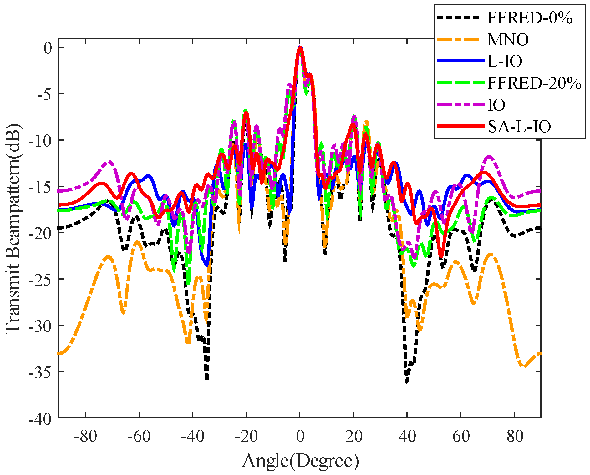
Figure 4 shows the transmit beampattern of different methods. In
Figure 4, all the methods can form mainlobes with similar width in either radar direction or communication direction. Moreover, the transmit power in the communication direction is about 3 dB lower than that in the radar direction, which is consistent with the simulation condition. In all methods, the proposed L-IO method has the lowest
and
, and the IO method has the largest
and
. For the non-constant modulus waveform design methods, the
of the proposed L-IO method is, respectively, reduced by 5.18 dB and 4.47 dB compared with the FFRED-0% and MNO methods, and the
of the proposed L-IO method is, respectively, reduced by 5.40 dB and 4.69 dB compared with the FFRED-0% and MNO methods. For the constant modulus waveform design methods, the proposed SA-L-IO method has the lowest
and
. Specifically, the
of the proposed SA-L-IO method is, respectively, reduced by 2.86 dB and 2.94 dB compared with the FFRED-20% and IO methods, and the
of the proposed SA-L-IO method is, respectively, reduced by 3.04 dB and 3.12 dB compared with the FFRED-20% and IO methods. Moreover, in terms of the
and
, the proposed constant modulus waveform design method, i.e., SA-L-IO, is better than the FFRED-0% and MNO methods, which are non-constant modulus waveform design methods.
In
Table 3, the
and
are given. From
Table 3, we can see that in all waveform design methods, the L-IO method has the lowest
and
. In the constant modulus waveform design methods, the SA-L-IO method has the lowest
and
. Moreover, the proposed SA-L-IO method is better than other methods, except for the proposed L-IO method, in terms of the
and
.
In
Figure 5, the pulse compression output in the radar mainlobe by different methods is shown.
Figure 5 shows that the pulse compression output in the radar direction is similar for different methods. Except for the radar direction, the L-IO method has the best radar mainlobe pulse compression output performance for the non-constant modulus waveform design methods, and the MNO method is better than the FFRED-0% method. Moreover, in the constant modulus waveform design methods, the SA-L-IO method has the best radar mainlobe pulse compression output performance, and the FFRED-20% method is better than the IO method. Note that in terms of the radar mainlobe pulse compression output, the proposed constant modulus waveform design method, i.e., SA-L-IO, is better than the FFRED-0% method, which is the non-constant modulus waveform design method.
In the scenario where the target direction is
and the user direction is
, i.e., the target is close to the user, the transmit beampattern of different methods is shown in
Figure 6. In all methods, the transmit power in the communication direction is about 3 dB lower than that in the radar direction, which is consistent with the simulation condition. In all methods, the proposed L-IO method has the lowest
and
, and the IO method has the largest
and
. For the non-constant modulus waveform design methods, the
of the proposed L-IO method is, respectively, reduced by 2.53 dB and 2.90 dB compared with the FFRED-0% and MNO methods, and the
of the proposed L-IO method is, respectively, reduced by 2.67 dB and 3.04 dB compared with the FFRED-0% and MNO methods. For the constant modulus waveform design methods, the proposed SA-L-IO method has the lowest
and
. Specifically, the
of the proposed SA-L-IO method is, respectively, reduced by 2.35 dB and 3.07 dB compared with the FFRED-20% and IO methods, and the
of the proposed SA-L-IO method is, respectively, reduced by 2.53 dB and 3.09 dB compared with the FFRED-20% and IO methods.
4.4. Communication Performance
In this subsection, we will compare the communication performance of the designed waveforms with other methods in terms of the BER.
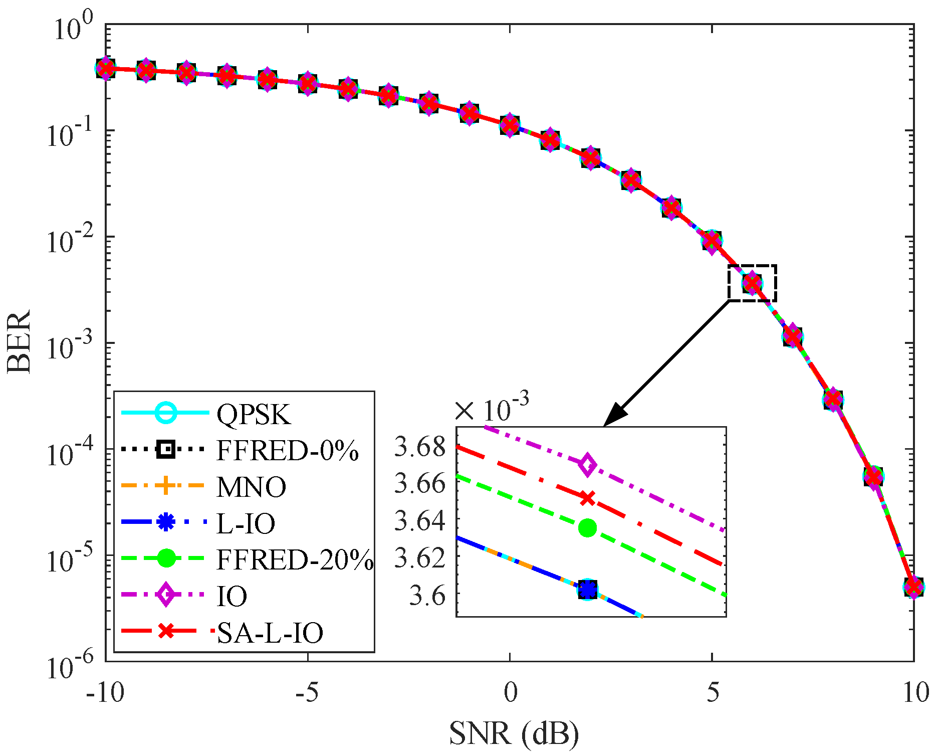
In
Figure 7, the BER of different methods versus the SNR is shown. For the non-constant modulus waveform design methods, the BER performance of the FFRED-0%, MNO, and L-IO methods is same as the desired QPSK waveform. For the constant modulus waveform design methods, the FFRED-20%, IO, and SA-L-IO methods also show similar performance, while they are slightly worse than the desired QPSK waveform in terms of BER. This is due to that the waveform error of the non-constant modulus waveform design methods is lower than that of the constant modulus waveform design methods.
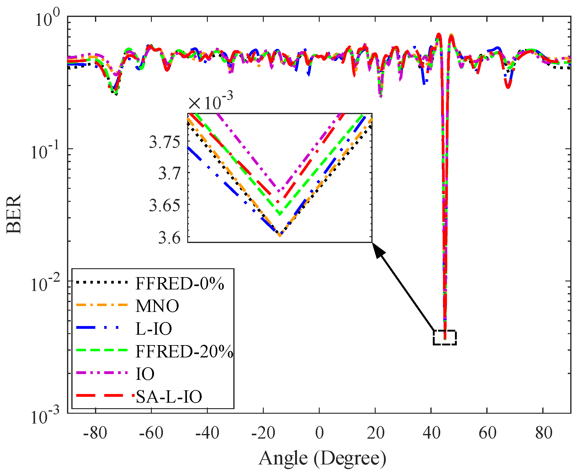
Figure 8 shows the BER in different direction when the SNR is 6 dB. It can be seen from
Figure 8 that in the communication direction, all the methods have the lowest BER. Moreover, in the communication direction, the FFRED-0%, MNO, and L-IO methods which are non-constant modulus waveform design methods have the same BER and they are better than the FFRED-20%, IO, and SA-L-IO methods, which are constant modulus waveform design methods.
4.5. Computational Complexity Performance
In this subsection, we will compare the proposed methods with other methods in terms of computational time.
In
Table 4, the computational time on a computer with a 2.5 GHz CPU and 32 GB memory is given. From
Table 4, we can see that the proposed L-IO and SA-L-IO methods need more computational time to achieve better performance.


