
An Approach for SAR Feature Reconfiguring Based on Periodic Phase Modulation with Inter-Pulse Time Bias


Abstract

1. Introduction
- First, the imaging analysis of the electromagnetic periodic modulation method with inter-pulse time bias based on the metasurface is proposed and studied, which is the theoretical basis for the subsequent target reconfigurability method.
- Then, an optimization method for target SAR feature reconfigurability based on the metasurface is proposed. This method enables the generation of corresponding modulation parameter schemes according to the desired characteristics, simultaneously fulfilling the requirements of airspace and energy distribution.
- To verify the effectiveness of the proposed method, parameter modulation schemes are obtained for configuring the interesting truck and passenger plane target features, respectively, and the corresponding imaging results are obtained, meeting the requirements within the allowable error range.
2. Materials and Methods
2.1. Basic Theory of Metasurface Modulation
2.2. Modulated Echo Model
3. A Periodic Phase Modulation Method with Inter-Pulse Time Bias
3.1. SAR Imaging Processing
3.2. Imaging Effects of Inter-Pulse Time Bias
4. A Method of Target SAR Feature Reconfigurability Based on Periodic Phase Modulation with Inter-Pulse Time Bias
4.1. Modulation Parameter Generation Algorithm (MPGA)
4.2. Parameter Mapping Matching Algorithm (PMMA)
- Energy indicators:
- 2.
- Image quality indicators:
5. Experiments and Results
5.1. Radar Parameters
5.2. Experimental Purpose
- Experiment 1: Reconfiguring the SAR signature array of a passenger plane
- Experiment 2: Reconfiguring the SAR signature array of a truck
5.3. Results and Analysis
6. Discussion
- It can be seen from the imaging results in Table 3 that the same metasurface target array can reconfigure different SAR features by switching the modulation parameters, and both Experiments 1 and 2 can hide the original metasurface array.
- It can be seen from the imaging area in Table 3 that this method can achieve a reconfigured target with adjustable size. The size of the reconfigured plane target in Experiment 1 is greater than the original metasurface array area, and the reconfigured truck target in Experiment 2 is smaller than the original metasurface array area. Therefore, the target size that can be reconfigured in the metasurface array area under the modulation of the parameter sets obtained in this paper is adjustable, i.e., it can be “small to large” or “large to small”.
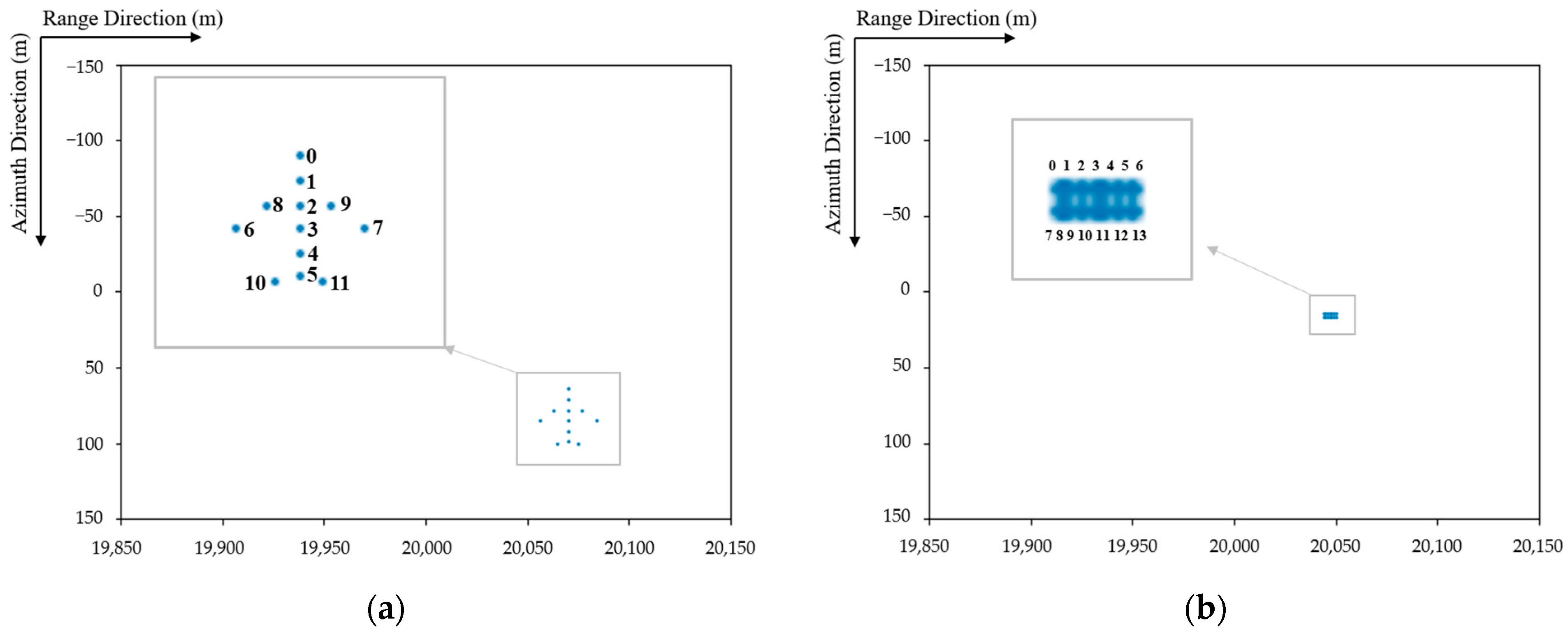
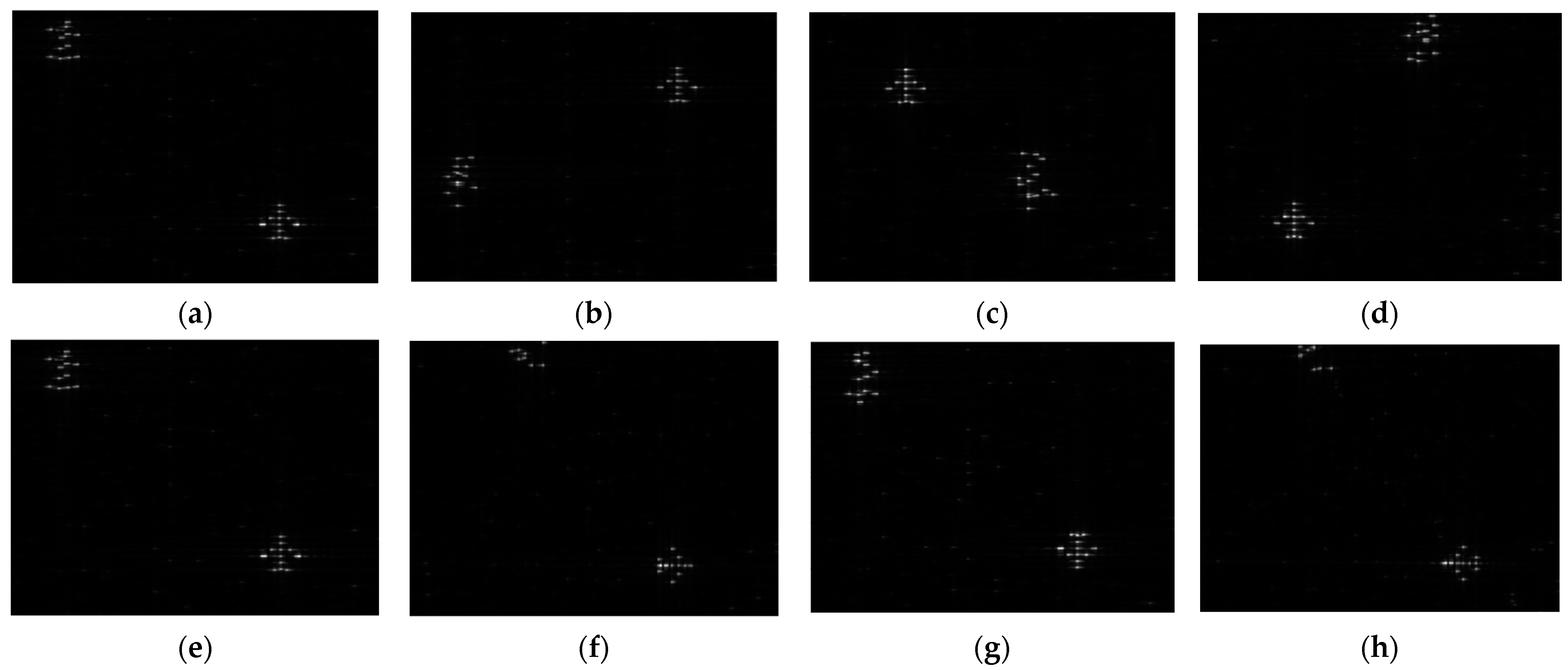
- It can be seen from the imaging center position in Table 3 and Figure 14a–d that this method can achieve a reconfigured target with adjustable positions. The target to be reconfigured is set as the input, and these position parameters of the expected targets are modifiable and adjustable. Through the reconfigurability algorithm, the modulation parameter set can be obtained, which can generate a reconfigured target within the error range. It can be seen from the imaging center position in Figure 14e–h that this method can achieve a reconfigured target with adjustable orientation, indicating that the proposed approach for modulated SAR features can meet the different spatial distribution requirements of the reconfigured target.
7. Conclusions
Author Contributions
Funding
Data Availability Statement
Acknowledgments
Conflicts of Interest
References
- Cumming, I.G.; Wong, F.H. Digital Processing of Synthetic Aperture Radar Data: Algorithms and Implementation; Artech House: Boston, MA, USA, 2005. [Google Scholar]
- Wang, J.; Quan, S.; Xing, S.; Li, Y.; Wu, H.; Meng, W. PSO-based fine polarimetric decomposition for ship scattering characterization. ISPRS J. Photogramm. Remote Sens. 2025, 220, 18–31. [Google Scholar] [CrossRef]
- Zhou, Y.; An, W.; Guo, F. Principles and Techniques of Electronic Countermeasures; Publishing House of Electronics Industry: Beijing, China, 2014. [Google Scholar]
- Tai, N.; Pan, Y.; Yuan, N. Quasi-coherent noise jamming to LFM radar based on pseudo-random sequence phase-modulation. Radioengineering 2015, 24, 1013–1024. [Google Scholar] [CrossRef]
- Chen, J. Principles of Radar Passive Jamming; National Defense Industry Press: Beijing, China, 2009. [Google Scholar]
- Li, A.; Singh, S.; Sievenpiper, D. Metasurfaces and their applications. Nanophotonics 2018, 7, 989–1011. [Google Scholar] [CrossRef]
- Zhao, B.; Huang, C.; Yang, J.; Song, J.; Guan, C.; Luo, X. Broadband polarization-insensitive tunable absorber using active frequency selective surface. IEEE Antennas Wirel. Propag. Lett. 2020, 19, 982–986. [Google Scholar] [CrossRef]
- Pitilakis, A.; Seckel, M.; Tasolamprou, A.C.; Liu, F.; Deltsidis, A.; Manessis, D.; Ostmann, A.; Kantartzis, N.V.; Liaskos, C.; Soukoulis, C.M.; et al. Multifunctional metasurface architecture for amplitude, polarization and wave-front control. Phys. Rev. Appl. 2022, 17, 064060. [Google Scholar] [CrossRef]
- Pitilakis, A.; Tsilipakos, O.; Liu, F.; Kossifos, K.M.; Tasolamprou, A.C.; Kwon, D.-H.; Mirmoosa, M.S.; Manessis, D.; Kantartzis, N.V.; Liaskos, C.; et al. A multi-functional reconfigurable metasurface: Electromagnetic design accounting for fabrication aspects. IEEE Trans. Antennas Propag. 2020, 69, 1440–1454. [Google Scholar] [CrossRef]
- Bai, H.; Yan, M.; Li, W.; Wang, J.; Zheng, L.; Wang, H. Tunable frequency selective surface with angular stability. IEEE Antennas Wirel. Propag. Lett. 2021, 20, 1108–1112. [Google Scholar] [CrossRef]
- Guo, Q.; Li, Z.; Su, J.; Song, J.; Yang, L.Y. Active frequency selective surface with wide reconfigurable passband. IEEE Access 2019, 7, 38348–38355. [Google Scholar] [CrossRef]
- Ghosh, S.; Srivastava, K.V. Broadband polarization-insensitive tunable frequency selective surface for wideband shielding. IEEE Trans. Electromagn. Compat. 2017, 60, 166–172. [Google Scholar] [CrossRef]
- Bakshi, S.C.; Mitra, D.; Ghosh, S. A frequency selective surface based reconfigurable rasorber with switchable transmis-sion/reflection band. IEEE Antennas Wirel. Propag. Lett. 2018, 18, 29–33. [Google Scholar] [CrossRef]
- Ebrahimi, A.; Shen, Z.; Withayachumnankul, W.; Al-Sarawi, S.F.; Abbott, D. Varactor-tunable second-order bandpass frequen-cy-selective surface with embedded bias network. IEEE Trans. Antennas Propag. 2016, 64, 1672–1680. [Google Scholar] [CrossRef]
- Chambers, B.; Tennant, A. The phase-switched screen. IEEE Antennas Propag. Mag. 2004, 46, 23–27. [Google Scholar] [CrossRef]
- Chang, Y.; Wang, L.; Li, B.; Jiao, W. Phase Switched Screen for Radar Cloaking Based on Reconfigurable Artificial Magnetic Conductor. IEEE Trans. Electromagn. Compat. 2021, 63, 1417–1422. [Google Scholar] [CrossRef]
- Lin, B.; Huang, W.; Lv, L.; Guo, J.; Wang, Z.; Zhu, R. Second-Order Polarization Frequency-Selective Surface. IEEE Trans. Antennas Propag. 2021, 69, 7976–7981. [Google Scholar] [CrossRef]
- Zaker, R.; Sadeghzadeh, A. A Low-Profile Design of Polarization Rotation Reflective Surface for Wideband RCS Reduction. IEEE Antennas Wirel. Propag. Lett. 2019, 18, 1794–1798. [Google Scholar] [CrossRef]
- Wang, X.; Liu, J.; Zhang, W.; Fu, Q.; Liu, Z.; Xie, X. Mathematic principles of interrupted-sampling repeater jamming (ISRJ). Sci. China Ser. F Inf. Sci. 2007, 50, 113–123. [Google Scholar] [CrossRef]
- Kozlov, V.; Vovchuk, D.; Ginzburg, P. Radar Range Deception with Time-Modulated Scatterers. IEEE Trans. Antennas Propag. 2023, 71, 4486–4491. [Google Scholar] [CrossRef]
- Kozlov, V.; Vovchuk, D.; Ginzburg, P. Direction of Arrival Deception with Time-Modulated Scatterers. IEEE Trans. Radar Syst. 2023, 1, 90–95. [Google Scholar] [CrossRef]
- Li, S.; Wang, J.; Fang, X.; Lu, G.; Li, M.; Chen, W. Jamming of ISAR Imaging with Time-Modulated Metasurface Partially Covered on Targets. IEEE Antennas Wirel. Propag. Lett. 2023, 22, 372–376. [Google Scholar] [CrossRef]
- Xu, H.; Quan, Y.; Zhou, X.; Chen, H.; Cui, T. A Novel Approach for Radar Passive Jamming Based on Multiphase Coding Rapid Modulation. IEEE Trans. Geosci. Remote Sens. 2023, 61, 1–14. [Google Scholar] [CrossRef]
- Sun, G.; Wang, J.; Xing, S.; Huang, D.; Feng, D.; Wang, S. A Flexible Conformal Multifunctional Time-Modulated Metasurface for Radar Characteristics Manipulation. IEEE Trans. Microw. Theory Tech. 2024, 72, 4249–4308. [Google Scholar] [CrossRef]
- Zhu, Y.; Fang, X.; Li, M.; Ramaccia, D.; Toscano, A.; Bilotti, F. Time–Frequency-Modulated Metasurface for False Target Generation in Symmetrical Triangular LFM Continuous-Wave Radars. Trans. Microw. Theory Tech. 2024, 1–13. [Google Scholar] [CrossRef]
- Ding, C.; Mu, H.; Meng, Y.; Zhao, M.; Zhang, Y.; Cai, T.; Meng, F. Time-Modulated Metasurface-Assisted Moving Target Jamming for Synthetic Aperture Radar. Trans. Microw. Theory Tech. 2025, 1–13. [Google Scholar] [CrossRef]
- Sui, R.; Wang, J.; Sun, G.; Xu, Z.; Feng, D. A Dual-Polarimetric High Range Resolution Profile Modulation Method Based on Time-Modulated APCM. Trans. Antennas Propag. 2025, 73, 1007–1017. [Google Scholar] [CrossRef]
- Xu, L.; Feng, D.; Wang, X. Matched-filter properties of linear-frequency-modulation radar signal reflected from a phase-switched screen. IET Radar Sonar Navig. 2016, 10, 318–324. [Google Scholar] [CrossRef]
- Xu, L.; Feng, D.; Wang, X. Improved Synthetic Aperture Radar Micro-Doppler Jamming Method Based on Phase-switched Screen. IET Radar Sonar Navig. 2016, 10, 525–534. [Google Scholar] [CrossRef]
- Wang, J.; Feng, D.; Xu, Z.; Wu, Q.; Hu, W. Time-Domain Digital-Coding Active Frequency Selective Surface Absorber/Reflector and Its Imaging Characteristics. IEEE Trans. Antennas Propag. 2021, 69, 3322–3331. [Google Scholar] [CrossRef]
- Wang, J.; Feng, D.; Kong, Y.; Quan, S.; Xing, S. Imaging Properties of Nonperiodic Time-Varying Active Frequency Selective Surface. IEEE Trans. Antennas Propag. 2022, 70, 5884–5891. [Google Scholar] [CrossRef]
- Li, H.; Li, Z.; Liu, K.; Xu, K.; Luo, C.; Lv, Y.; Deng, Y. A Broadband Information Metasurface-Assisted Target Jamming System for Synthetic Aperture Radar. Remote Sens. 2024, 16, 1499. [Google Scholar] [CrossRef]
- Fang, X.; Li, M.; Wang, S.; Ai, X.; Wang, W.; Liu, J. EM Scattering Center Model-Guided Passive SAR Deception Using Diverse Frequency Time-Modulation. Trans. Geosci. Remote Sens. 2024, 62, 1–13. [Google Scholar] [CrossRef]
- Mu, H.; Ding, C.; Guan, C.; Zhang, Y.; Cai, T.; Meng, F. Subsection-Shift-Doppler-Frequency Jamming Based on Phase-Tunable Metasurface Against SAR Imaging. Trans. Geosci. Remote Sens. 2024, 62, 1–15. [Google Scholar] [CrossRef]


| Range Domain Parameters | Value | Azimuth Domain Parameters | Value |
|---|---|---|---|
| Scene center distance | 20 km | Radar speed | 150 m/s |
| Pulse duration | 2.5 μs | Radar operating frequency | 10 GHz |
| Range modulation frequency | 20 MHz/μs | Azimuth modulation frequency | 75 Hz/s |
| Signal bandwidth | 1 MHz | Antenna length | 3.3325 m |
| Range sampling rate | 60 MHz | Azimuth sampling rate | 200 Hz |
| Slant angle | 0° |
| Label | Experiment 1: Modulation Period (Seconds) | Experiment 2: Modulation Period (Seconds) |
|---|---|---|
| 0 | 8.327539819376977 × 10⁻⁸ | 1.1355662578026702 × 10⁻⁷ |
| 1 | 8.327533920724061 × 10⁻⁸ | 1.1355659029373009 × 10⁻⁷ |
| 2 | 9.861594529025383 × 10⁻⁸ | 1.1186205053270461 × 10⁻⁷ |
| 3 | 8.817454217418264 × 10⁻⁸ | 1.1530323251511429 × 10⁻⁷ |
| 4 | 8.327533226764895 × 10⁻⁸ | 1.0706884305570732 × 10⁻⁷ |
| 5 | 9.029870475152497 × 10⁻⁸ | 1.1021728881224057 × 10⁻⁷ |
| 6 | 9.861588689878635 × 10⁻⁸ | 1.1186195974914579 × 10⁻⁷ |
| 7 | 7.973242777040326 × 10⁻⁸ | 1.2286553031218273 × 10⁻⁷ |
| 8 | 7.420629065134477 × 10⁻⁸ | 1.228654887697628 × 10⁻⁷ |
| 9 | 8.614643839673231 × 10⁻⁸ | 1.1355657093743721 × 10⁻⁷ |
| 10 | 8.614640126455485 × 10⁻⁸ | 1.135565677113884 × 10⁻⁷ |
| 11 | 8.614636413237739 × 10⁻⁸ | 1.1530319592828522 × 10⁻⁷ |
| 12 | 8.146543304691033 × 10⁻⁸ | 1.2088407857756882 × 10⁻⁷ |
| 13 | 7.420624932313623 × 10⁻⁸ | 1.1186195974914579 × 10⁻⁷ |
| Experiment | Imaging Results | Imaging Area | Imaging Center Position |
|---|---|---|---|
| 0 1 | 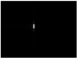 | 3 m × 18 m | (19,981.5, −14) |
| 1 | 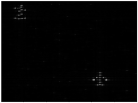 | 28.45 m × 37.81 m | (20,085, 70) |
| 2 | 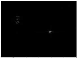 | 7.495 m × 2.47 m | (20,047, 15) |
Disclaimer/Publisher’s Note: The statements, opinions and data contained in all publications are solely those of the individual author(s) and contributor(s) and not of MDPI and/or the editor(s). MDPI and/or the editor(s) disclaim responsibility for any injury to people or property resulting from any ideas, methods, instructions or products referred to in the content. |
© 2025 by the authors. Licensee MDPI, Basel, Switzerland. This article is an open access article distributed under the terms and conditions of the Creative Commons Attribution (CC BY) license (https://creativecommons.org/licenses/by/4.0/).
Share and Cite
Zhu, L.; Wang, J.; Feng, D. An Approach for SAR Feature Reconfiguring Based on Periodic Phase Modulation with Inter-Pulse Time Bias. Remote Sens. 2025, 17, 991. https://doi.org/10.3390/rs17060991
Zhu L, Wang J, Feng D. An Approach for SAR Feature Reconfiguring Based on Periodic Phase Modulation with Inter-Pulse Time Bias. Remote Sensing. 2025; 17(6):991. https://doi.org/10.3390/rs17060991
Chicago/Turabian StyleZhu, Liwen, Junjie Wang, and Dejun Feng. 2025. "An Approach for SAR Feature Reconfiguring Based on Periodic Phase Modulation with Inter-Pulse Time Bias" Remote Sensing 17, no. 6: 991. https://doi.org/10.3390/rs17060991
APA StyleZhu, L., Wang, J., & Feng, D. (2025). An Approach for SAR Feature Reconfiguring Based on Periodic Phase Modulation with Inter-Pulse Time Bias. Remote Sensing, 17(6), 991. https://doi.org/10.3390/rs17060991