In this section, we derive an intensity transformation for enhancing bright features, such as point-like scatterers buried in speckle background noise, from first-principles. We begin the derivation by assuming that the point scatterers can be modeled as unit impulses when visualized in the spatial domain after deconvolving the input image with the imaging system’s PSF. As a result, this leads us to deriving a sinc function in the intensity domain from proposing that the transformation can be expressed as a sum of shifted complex exponentials. Following this, we introduce the bright feature transform and show that it is free of parameters, and then demonstrate that the BFT achieves the same level of transformation as a sinc function. We then present our proposed trigonometric (trig) difference filter designed for mitigating the scattering impact of background noise, with a particular emphasis on visual saturation caused by speckle reflectors, to improve the visual detection and interpretation of bright prominent features after tone mapping. We also present a fast version of this filter and then show that these proposed transformations can be applied at the feature extraction stage before generating binary masks in a bright scatterer detection pipeline.
2.1. Theoretical Formulation and Analysis of the Bright Feature Transform
Given an N×M single-look complex (SLC) synthetic aperture image, where N is the number of rows and M is the number of columns, the intensity value of a single pixel from the SLC imagery can be represented as
, where
is the amplitude,
is the phase, and
is the pixel location. We discard the phase information in this paper and only focus on the normalized version of the amplitude data such that
, which allows us to make the assumption that the point-like scatterers can be modeled as unit impulses. Following this, the tone mapped imagery that highlights the bright features can be defined as,
where
is the normalized input amplitude image containing the unit impulses,
is the tone mapping filter, and ⊙ refers to the Hadamard element-wise multiplication [
25].
We use a complex intensity-based transformation to design the tone mapping filter
analogous to the inverse discrete Fourier transform of a complex exponential or unit rectangle function (when considering
) so that the output
boosts the contrast of the bright scatterers relative to the background in preparation for downstream image characterization or processing. Further, this transformation can either be applied globally to every pixel or defined for a specific region of the image, depending upon the application of the operation. Here, we show the derivation for the single pixel
and then generalize the operation to be applied globally across the entire image
. We express the transformation as a linear combination of shifted complex exponentials, where the shift captures the difference between the brightest pixel value in the image/region to the current pixel value
,
where
,
L is the number of classes for classification,
k is the class label, and
is the pixel intensity to highlight; for this derivation,
, assuming the prominent scatterers are the brightest features in the image and are unit impulses. Intuitively, Equation (
2) is a filter that measures the phase shift
between the maximum pixel and the current pixel
. When there is no shift,
, the operation leaves the current pixel unaltered when applied in Equation (
1) and when a shift is detected,
, the current pixel gets re-scaled to a value closer to zero when applied in Equation (
1). When Equation (
2) is applied on the full image
, the operation visually accentuates the prominent scatters and other bright features in the imagery.
Further, we truncate the infinite series for one period, in our case
L, for first quadrant support such that no two class labels,
k, share the same complex value
. Thus, we express the transformation as a finite sum ranging from 0 to
,
As the finite version of this series converges, it can be expressed in closed-form as follows:
which is the intensity domain version of a sinc function for multi-class detection
. Equation (
4) can be understood as the filter’s response to unit impulses in the intensity domain, assuming that the pixels of the prominent scatterers are unit valued. In practice, the prominent scatterer can have pixel values that include unity and values close to 1 in the blurred version of the imagery (before deconvolution is performed). This effect is due to the PSF smearing or distorting the return energy of the scatterer across multiple neighboring pixels. Therefore, in the limit that the pixel value
is close to unity in Equation (
4) such that the sine arguments are
close to zero, the sine functions in the numerator and denominator can be approximated as the zero-order term in their Taylor series expansions i.e.,
. When
, Equation (
4) becomes
, which shows that dark pixels are mapped to zero and bright features in
are highlighted as candidate point-objects of opportunity. Also, it is worth mentioning that Equation (
4) is useful for visually detecting unit impulses when the deblurred or deconvolved version of
is presented. For this paper, we assume that
is reconstructed synthetic aperture imagery that has been blurred by the imaging system’s PSF. Therefore, our objective is to exploit the properties presented in deriving Equation (
4) by modifying two assumptions, such as the following: (1) the point scatterer is unit valued, and (2) we are operating in the multiclass setting where
.
Therefore, we can consider only two classes,
, where
is the signal, and
is the background noise labeled as clutter, which fully describes the problem at hand, a signal buried in speckle noise. As a result, Equation (
3) provides the first-order term which gives,
a sine function with first-quadrant support,
. Implementing Equation (
5) over Equation (
4) serves three purposes: (1) it is computationally faster, (2) it is free of parameters such as
L and
, and (3) there are no division by zero issues in the denominator. Also, Equation (
5) assumes that the pixels of the signal can be spread across many neighboring pixels due to the smearing of the PSF after capturing the data, where again, Equation (
4) assumes that pixels of the bright scatterer are represented as unit impulses in the data product. These two effects are captured in the parameter
, where Equation (
5) removes the assumption that the prominent scatterer is only captured by the brightest pixel in the imagery. Thus, we use Equation (
5) in our experiments as the bright feature transform (BFT) and
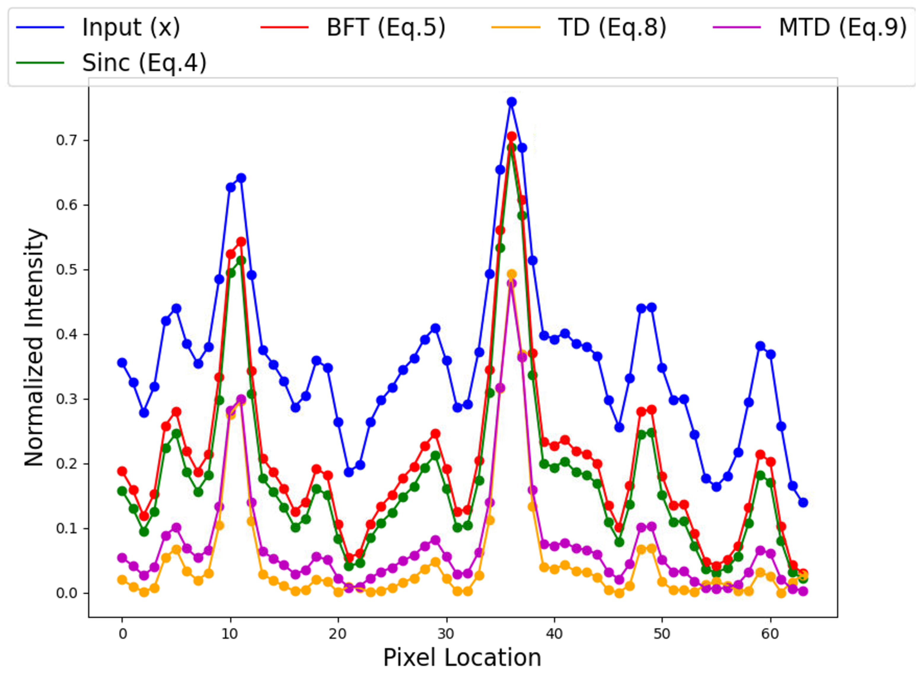
Figure 1 shows the line intensity profile of the BFT against the input and the sinc function, as well as two other methods that are introduced later in the paper, for a simulated prominent scatterer. What is observed in the figure is that both the BFT and the sinc function produce nearly identical transformations in the region of the scatterer, with the trade-off being that the BFT enhances sidelobe peaks slightly stronger than the sinc function.
2.2. Bright Feature Transform Enhancement for Noise Mitigation and Processing Efficiency
Continuing with our analysis, a similar transformation can be derived for filtering dark features by reversing the sign of every other term in Equation (
3). This is performed by rearranging the transformation to include the factor
such that it is an alternating series,
again, assuming only two classes provide the first-order term,
which is a cosine function with first-quadrant support. This function highlights dark regions in the imagery, such as shadows and other low-intensity prominent features, as well as the background noise. Applying a negative sign to Equation (
7) inverts the image and places
in the range of
vs.
. This transformation states that dark pixels are mapped to more negative values, while bright pixels are mapped to zero. We can exploit this property to reduce the background noise, particularly scenes saturated by speckle reflectors and other noise scatterers, to enhance the point scatterer.
Therefore, to suppress the intensity levels related to background noise which are highlighted in Equation (
7), we introduce a trig difference (TD) function by subtracting Equation (
7) from Equation (
5),
Equation (
8) maximizes the distance between the noise and prominent scatterer pixels by expanding the dynamic range from
to
. Applying Equation (
8) on
in Equation (
1) yields a
with minimal noise and small sidelobes, as shown in
Figure 1, when comparing the line profile of a scatterer against the input, BFT, and sinc function. Further, the benefit of implementing Equation (
8) over Equation (
5) is that it suppresses the background noise by clipping the intensity values to
, which, in turn, makes the prominent scatterer’s features more profound due to having a steeper drop off and narrower peak. The trade-off is that some of the low-intensity pixels at the tail-end of the prominent scatterer intensity profile may get suppressed, and Equation (
8) has a longer computational processing time due to having two terms in the filter.
To reduce the TD filter’s computational speed to the same order as Equation (
5), we set
in the first term in Equation (
8),
to produce a fast method to visually detect possible bright scatterers of opportunity when used in Equation (
1),
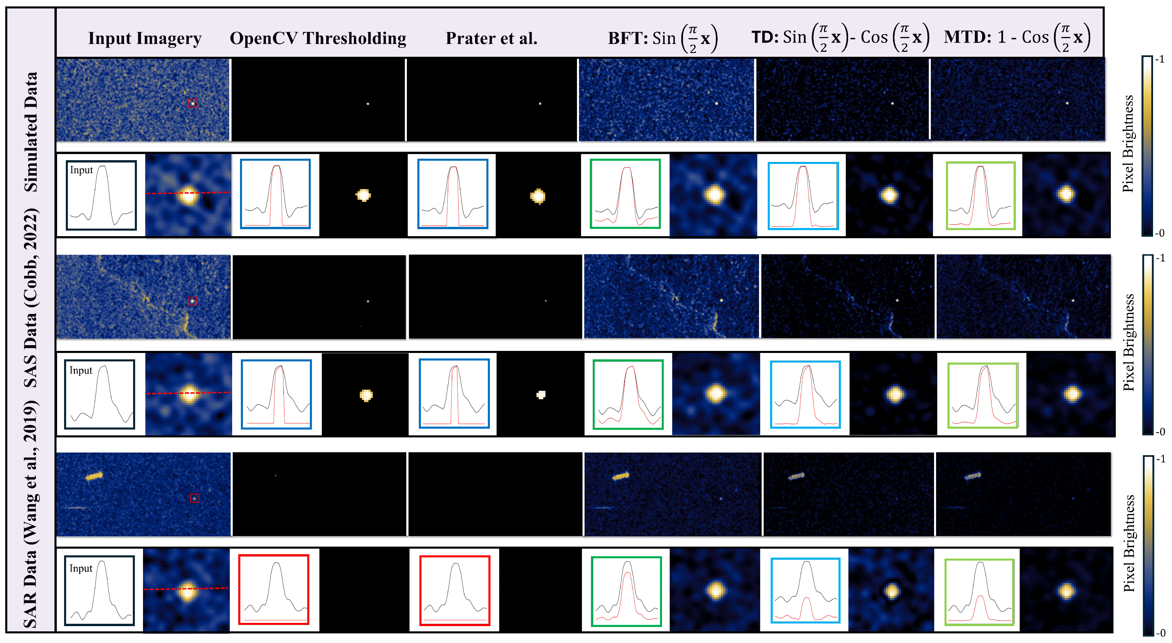
Moreover, Equation (
10) is a useful technique for characterizing synthetic aperture imagery; specifically, image resolution estimation, image sharpness enhancement, and deconvolution using prominent scatterers to estimate the PSF in the presence of strong speckle noise and other bright reflectors, as shown in
Figure 2. We label this method as the modified trig difference (MTD) filter, which is a shifted version of the inverted representation of Equation (
7), with the data in the range of
instead of
.
Figure 1 illustrates the typical shape of the derived transformations after taking a 1D intensity profile across a simulated prominent scatterer. The TD filter (Equation (
8)) produces the narrowest and most profound main peak width out of all the transformations, with the sidelobes being reduced the steepest. The MTD filter (Equation (
9)) produces a sharper main lobe than the BFT and the sinc function with smaller sidelobes, which could be correlated with speckle noise, making it an ideal filter for enhancing visual detection of bright features in synthetic aperture imagery in the presences of noise.


