Abstract
Most electromagnetic metasurfaces only control a single property of electromagnetic waves, such as the phase, amplitude, polarization or frequency, leading to a shortage in capacity and security in communication and a decrease in radar imaging efficiency. By switching the states of four PIN diodes soldered between adjacent resonant arms, cross-polarization and co-polarization reflected waves both with a 1-bit phase can be implemented. The simulation results demonstrate that the proposed metasurface operates within a frequency band of 5.7 GHz to 5.88 GHz, covering ISM 5.8 GHz. Within its operational frequency range, in the cross-polarization reflection case, the losses of the 1-bit phase reflected wave are from 1 dB to 1.5 dB, with a high polarization conversion rate exceeding 91% and even reaching 99%. For the co-polarization reflection case, the losses of the 1-bit reflected wave are from 0.3 dB to 2 dB, and the polarization conversion is almost 100%. The phase difference of the reflected wave in both cases can be realized as about 180°, which satisfies the 1-bit phase requirement for building a good property of beam steering. Upon constructing a 10 × 10 small array, the cross-polarized reflection beam can be steered within the range of elevation angle from 0° to 45° and the elevation angle from 0° to 30° in the co-polarized reflection case.
1. Introduction
Metasurfaces, as newly emerged two-dimensional materials, can introduce abrupt phase changes on the unit cell surface after specialized design, achieving control over the amplitude, phase, frequency and polarization mode of electromagnetic waves. They can offer superior properties, such as strong flexibility, high precision and good fidelity. Typically, metasurfaces can be divided into two types: those without tunable devices, which achieve wave control by placing different types of passive unit cells alternately [1,2]. Using this kind of metasurface, the arrangement of the unit cells needs to be modified manually according to the changed synthesized beam direction. The other is with integrated tunable devices, and this type can realize wave control by switching the on-off state of these tunable devices rather than utilizing different unit cells and modifying these unit cells’ arrangement [3,4,5]. Clearly, the latter is more flexible.
In numerous electromagnetic applications, such as wireless communication and radar imaging, there is a growing demand for metasurfaces with a simplified structure, low profile and high efficiency [6,7]. Although current research on metasurfaces has explored high-speed data processing, flexible configuration of embedded systems [8] and the impact of incident angles on metasurfaces [9], challenges remain in reflection field steering and shaping, such as a high reflection loss and narrow sweeping angle. Additionally, considering the utilization of electromagnetic waves and the stability of reflection field steering and shaping, research on multi-polarized conversion metasurface is necessary. However, this poses a significant challenge in achieving low loss, as leveraging multi-polarized incident waves and achieving multi-polarized wave conversion reflection require more complex coupled circuits. This complexity leads to more intricate structures and additional losses. Thus, low-loss multi-polarization conversion metasurfaces have become an urgent research trend. However, the majority of existing studies focus on single polarization conversion [10,11,12,13], which restricts the utilization efficiency of electromagnetic waves since other polarized waves cannot be used. Although recent researchers have made efforts to generate multi-polarized waves [3,14,15,16], these efforts either lack the ability of dynamically tuning polarization, which is essential for beam steering, shaping and other applications [17,18,19], or suffer from a low PCR (polarization conversion rate) and high reflection loss [20].
This paper investigates a single-layer, 1-bit electrically tunable metasurface capable of achieving both 1-bit-phase cross-polarization and 1-bit-phase co-polarization reflection with a high PCR and low loss, which has a good capacity of beam steering and shaping. The operational frequency band ranges from 5.7 GHz to 5.88 GHz, which covers ISM (Industrial, Scientific, and Medical) 5.8 GHz (5.725~5.85 GHz). Within its operational band, its reflection loss approximates 1 dB~1.5 dB in the cross-polarization reflection case and 0.3 dB~2 dB in the co-polarization reflection case, and the PCR exceeds 91% in both cases, even nearly 100% in some bands. Meanwhile, it can implement beam steering in the desired direction since a reflection wave with a 180° phase difference can be created, namely, 1-bit phase control, which makes reflected waves totally in the phase or in reverse. After propagation and being vectorially synthesized, these reflected waves focused toward the desired directions, which was explored by simulations with a 10 × 10 small array.
2. Metasurface’s Unit Cell Design
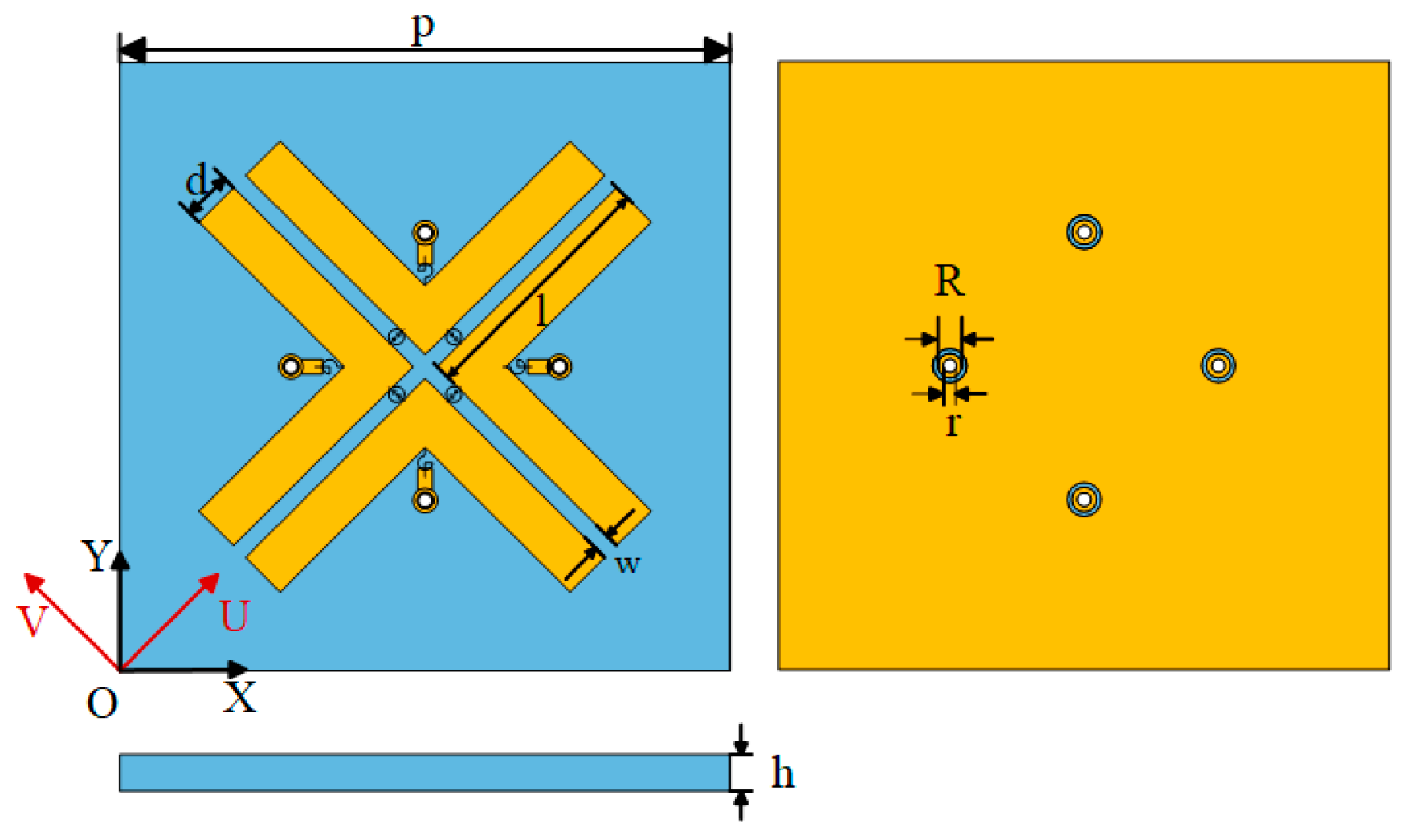
A metasurface is an array constructed by a lot of metasurface unit cells. The configuration of the proposed metasurface’s unit cell is shown in Figure 1. It is composed of a patch, a single-layer substrate and a ground. The substrate is Rogers RT5870 (from Rogers Corporation, Shenzhen, China), with a dielectric constant of 2.33 and a loss tangent of 0.0012. The patch consists of four L-shaped resonant arms. Each arm of the L-shaped patch is about a quarter of the wavelength at 5.8 GHz, which causes the incident wave to induce resonance at ISM 5.8 GHz and then be reflected at ISM 5.8 GHz. In addition, coupled with the ground and combined with lumped elements, these arms can change their surface current by half a wavelength. Therefore, the phase of the reflected wave can be modified by 180°, and this is how the 1-bit phase modulation is achieved. After the simulation was conducted by the software CST (Computer Simulation Technology) Studio Suite 2022 (from CST China Ltd., Shanghai, China), the proposed unit cell was verified to work within the frequency range of 5.7~5.88 GHz, covering the ISM 5.8 GHz (5.725~5.85 GHz) as we deduced. The incident wave in this band can induce the patch resonance, be reflected, change polarization and be utilized for the steering beam, which does not happen out of the working range.
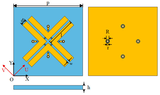
Figure 1.
Structure of the metasurface’s unit cell. p = 25 mm, h = 1.6 mm, l = 10.4 mm, w = 0.7 mm, d = 2 mm, R = 0.5 mm, and r = 0.3 mm.
As for the integrated lumped components, four PIN (Positive–Intrinsic–Negative) diodes (type: SKYWORKS SMP1321-079) were soldered between these arms for changing the surface current path and manipulating the polarization of the reflected wave. Four chokes (type: AVX HLQ028R2) were soldered at the corner of the four L-shaped resonant elements connecting the patch to the control circuit through metal vias. They were used to provide DC voltage for the diodes and prevent high-frequency currents from entering the control circuit. In the simulation, the lumped elements were modeled by importing their S2P files.
To simplify the analysis, two coordinate systems were introduced, as shown in Figure 1. One is the Cartesian coordinate system (X-O-Y), and the other one (U-O-V) is formed by a 45° counterclockwise rotation of this Cartesian coordinate system. The incident or reflected wave with x or y linear polarization can be decomposed into U and V axes, where the arms lie. By modifying the path of the surface current lying on these arms, the phase and polarization of the synthesized reflected wave can be changed. Take the incident wave with +y polarization, for example, it can be decomposed into +U and +V components. The working principle on how to achieve 1-bit cross-polarization and 1-bit co-polarization reflected waves is as follows:
Cross-Polarization (CP): In state 1 (CP1), the two PIN diodes parallel to the U-axis are conducting, while the other two PIN diodes parallel to the V-axis are in an off state. Thus, the surface current of the +U component is extended by half a wavelength, which causes the phase of the reflected wave to rotate by 180° to form a −U reflected wave. Since the +V reflected wave is unchanged, the surface current in the +V-axis stays the same. After synthesizing the newly conformed reflected wave, a −x linear polarized wave can be obtained. In state 2 (CP2), the states of the diodes are reversed, and the synthesis reflected wave comes to +x linear polarization. Obviously, in addition to implementing cross-polarization, the reflected wave of the two states has a phase difference of 180°, which achieves the purpose of 1-bit phase modulation.
Co-Polarization (CoP): In state 1 (CoP1), all four PIN diodes are on. The current surface in the +U and +V axes is extended by half a wavelength to form −U and −V reflected waves. The synthesis reflected wave is −y linear polarization. In state 2 (CoP2), the situation is completely the opposite, with all diodes off, and the reflected waves are still +y-polarized. In addition, the reflected wave of the two states achieves 1-bit phase modulation, with a 180° phase difference as well.
Three indicators were introduced to measure the properties of the metasurface unit cell. The first one is the phase rotation angle difference, which is used to measure the ability of a decomposed wave to rotate 180°. It can be expressed as:
where “” and “” are the phase rotation angle difference before and after switching diodes in U and V directions separately. The subscript “i” represents the initial resonance. Thus, “” and “”, respectively, denote the initially resonant phases happening in U and V directions. The subscript “s” represents the resonance after switching diodes. Similarly, “” and “” are separately resonant phases after switching diodes in U and V directions. When and or and , the polarization of reflected wave is not changed; when and or and , a cross-polarization reflected wave is obtained.
The second indicator is the PCR, which is used to measure the efficiency of the reflecting corresponding polarized wave. Also, take the +y-polarized incident wave, for example. Let denote the cross-polarized reflection coefficient representing the amount of the x-polarized reflected wave, and denote the co-polarized reflection coefficient. Thus, the PCR in CP and CoP can be defined, respectively, as:
The last indicator is the phase difference between the two states of CP or CoP, which is crucial for beam steering and shaping. Here, we define it as:
where and are, respectively, the phase of the reflected wave in CP1 or CoP1 and CP2 or CoP2.
From the view of beam steering and shaping, we built a N × N array constructed by these unit cells. The synthesized field after superposition in the observation space can be expressed as:
where we assume that there are M unit cells working in CP1 or CoP1. Clearly, the remaining N × N − M unit cells operate in CP2 or CoP2. is the incident electric field along the y direction. is the reflected field in CP1 or CoP1. is the reflected field in CP2 or CoP2. It is worth mentioning that from the view of synthesizing the reflected field, for and , when the reflected wave is cross-polarized, the incident electric field has little influence on beam steering and shaping formed by the reflected field. However, if the wave is co-polarized, beam steering and shaping will be significantly affected by the incident field.
Obviously, for controlling the beam, we hope the reflected field cannot be interfered by the incident field. Thus, the main idea of this design is to produce a cross-polarization reflected wave, and that is why a little frequency shift happens in the co-polarization case, which is acceptable.
Furthermore, in order to obtain the optimized field toward the desired direction, we used the ergodic method. Initially, the original field in the desired direction is recorded as . Then, change the first unit cell’s state, for example, from state 1 to state 2, and record the field as . If , the changed state should be saved. Otherwise, keep the original state of the unit cell. Through this method, all the unit cell states are determined, and the optimized field toward the desired direction is acquired.
3. Simulation Result
3.1. Unit Cell Simulation
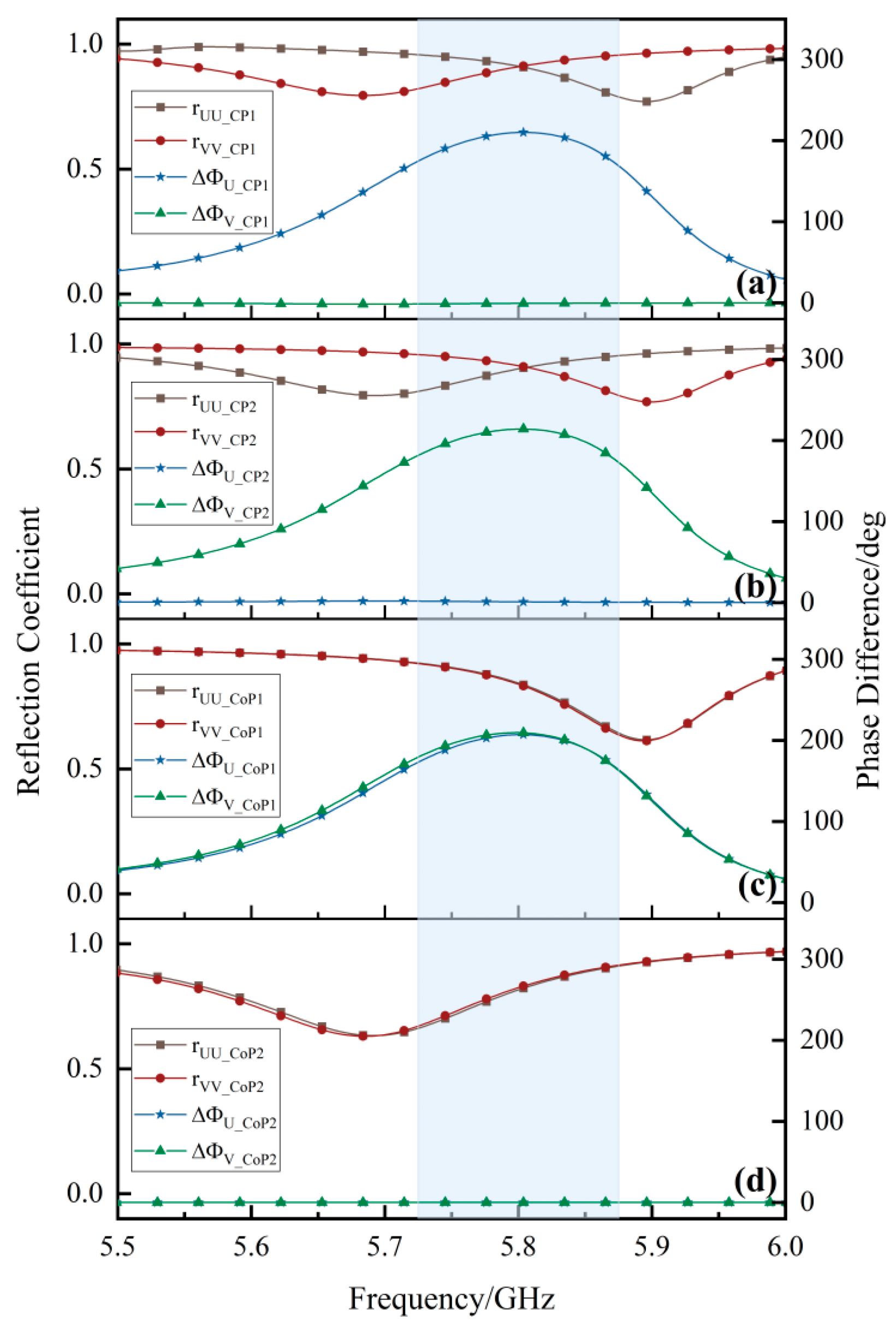
To verify the validity of the proposed metasurface, we gave the phase difference and reflection coefficient of the unit cell in the U and V axes, as shown in Figure 2. At ISM 5.8 GHz, the +y-polarized incident wave was decomposed into the +U and +V directions. When two reflection coefficients are equal, , , and , as shown in Figure 2a, since the +V polarized wave is not rotated, but the +U polarized wave is rotated 180°, and after synthesizing these two waves, −x cross-polarization can be achieved. Similarly, +x cross-polarization can be obtained when the two reflection coefficients are equal, , , and , as shown in Figure 2b. Apparently, the −x polarized reflected wave and the +x polarized reflected wave have a 180° phase difference, and they are both cross-polarizations of the +y-polarized incident wave. Therefore, the 1-bit-phase cross-polarization reflection wave is well-achieved. In the same way, −y and +y co-polarization occur when two reflection coefficients are, respectively, equal, , , and the phases separately are and , as shown in Figure 2c,d. Clearly, 1-bit-phase co-polarization is implemented as well.
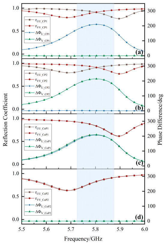
Figure 2.
Reflection coefficient and phase difference in (a) CP1, (b) CP2, (c) CoP1 and (d) CoP2. Rectangle shadow is working band (5.7~5.88 GHz).
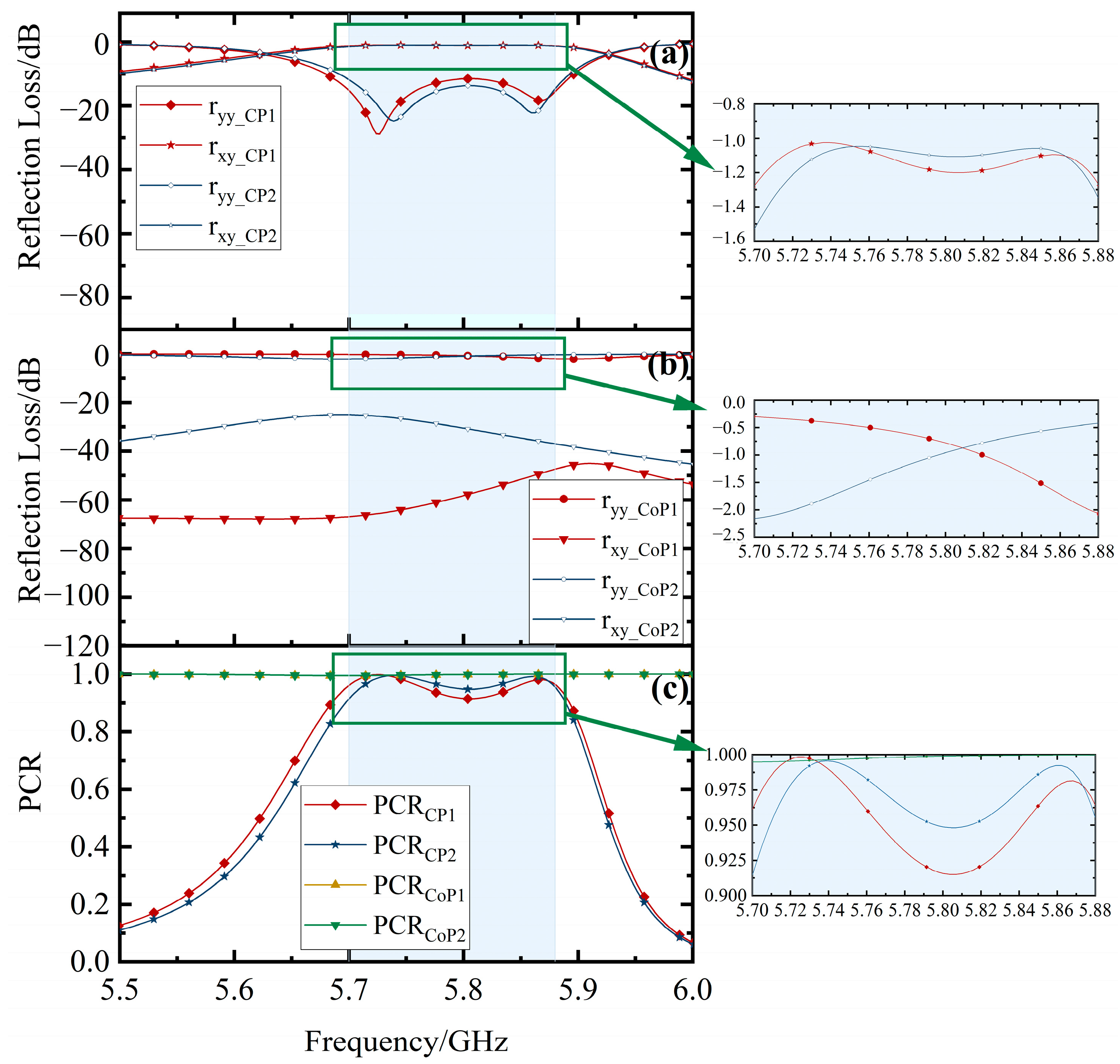
Figure 3 illustrates the reflection loss and PCR in different cases when the incident wave is y-polarized. Figure 3a presents the reflection loss in CP1 and CP2. In both states, the co-polarized return loss exceeds 11 dB, while the cross-polarized return loss is 1 dB~1.5 dB. There is nearly no co-polarized reflection wave. In Figure 3b, the cross-polarized return loss exceeds 47.3 dB in CoP1 and exceeds 25 dB in CoP2, while the co-polarized return loss is 0.3 dB~2.15 dB. This indicates that the reflected wave is predominantly co-polarized. Additionally, as Figure 3c shows, CP1 and CP2 have a high , which exceeds 91%. The maximum value can reach 99%. The remains stable at 100% in CoP1 and CoP2 across the whole band.
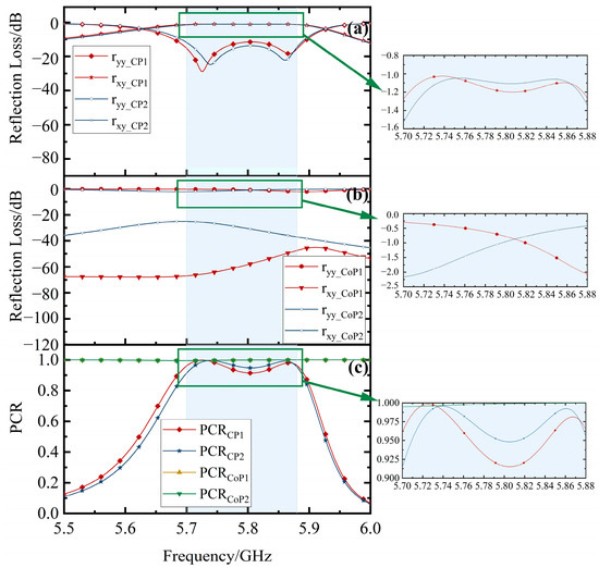
Figure 3.
Reflection loss in (a) CP1 and CP2 and (b) CoP1 and CoP2. (c) PCR in CP1, CP2, CoP1 and CoP2. Rectangle shadow is working band (5.7~5.88 GHz).
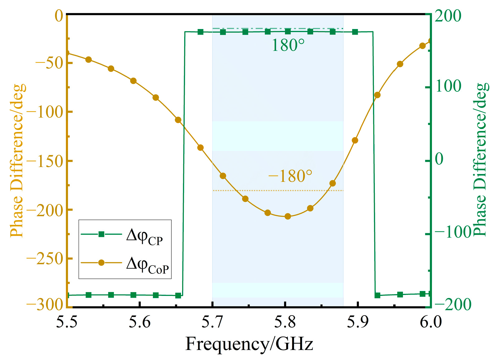
Figure 4 shows the phase difference between the two states. In the CP case, a consistent 175° phase difference is maintained across the whole band. In the CoP case, the phase difference ranges from −207° to −152°, still implementing 1-bit phase control for the reflected wave.
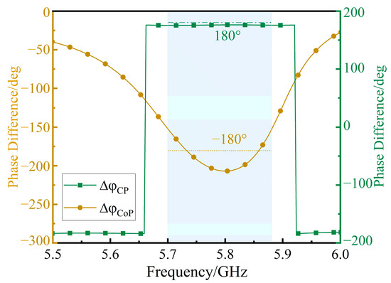
Figure 4.
Phase difference in CP case and CoP case. Rectangle shadow is working band (5.7~5.88 GHz).
Figure 3 and Figure 4 demonstrate that this metasurface has a good transformation efficiency with a low reflection loss. Moreover, as previously noted, this design meets the objective of achieving a cross-polarized reflected wave since the reflected field is not interfered with by the incident field from the view of the controlling beam. Hence, the return loss and phase difference in the CP case are better than those in the CoP case. In a supplementary way, this design has the ability to achieve a co-polarized reflected field, which is predictably not as good as that in the cross-polarization case.
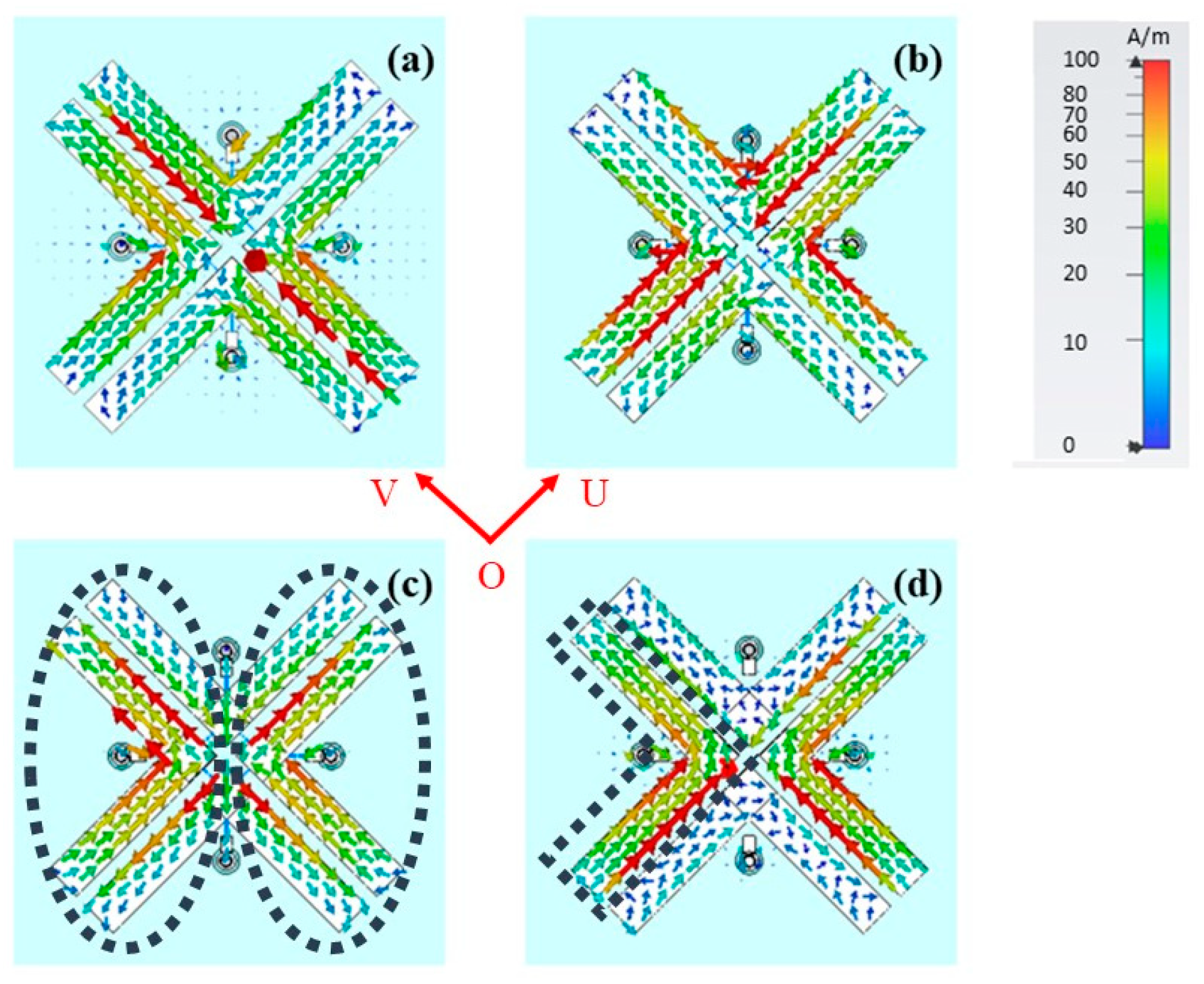
Figure 5 shows the surface current in all cases. In Figure 5a, for the L-shaped patch arm in the U direction, the surface current direction is the same, indicating an extended resonant current path that is half a wavelength. This phenomenon confirms that the polarization direction in the U direction can undergo a 180° reversal. While this cannot happen in the V direction. Therefore, −x cross-polarization is achieved. Similarly, in Figure 5b, this extension occurs in the V direction, synthesizing +x cross-polarization. In Figure 5c, when all diodes are turned on, by dividing the metasurface along the center into the left and right sides, each side forms its own current loop, allowing the polarization direction in both the U and V directions to be reversed, constructing −y polarization. In Figure 5d, although some weaker currents are influenced by the coupling of stronger currents, causing a deviation in the direction, and the coupling effect becomes more pronounced closer to the center point, resonance still occurs only on each non-conducting L-shaped patch. As a result, the polarization phase in both the U and V directions remains unchanged, resulting in +y polarization. These phenomena have good agreement with the theoretical analysis.
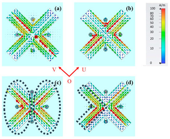
Figure 5.
Surface current at 5.8 GHz. (a) CP1. (b) CP2. (c) CoP1. The dashed circular outlines indicate the current loop. (d) CoP2. The closed dashed lines indicate the self-resonant current path.
3.2. 10 × 10 Array Simulation
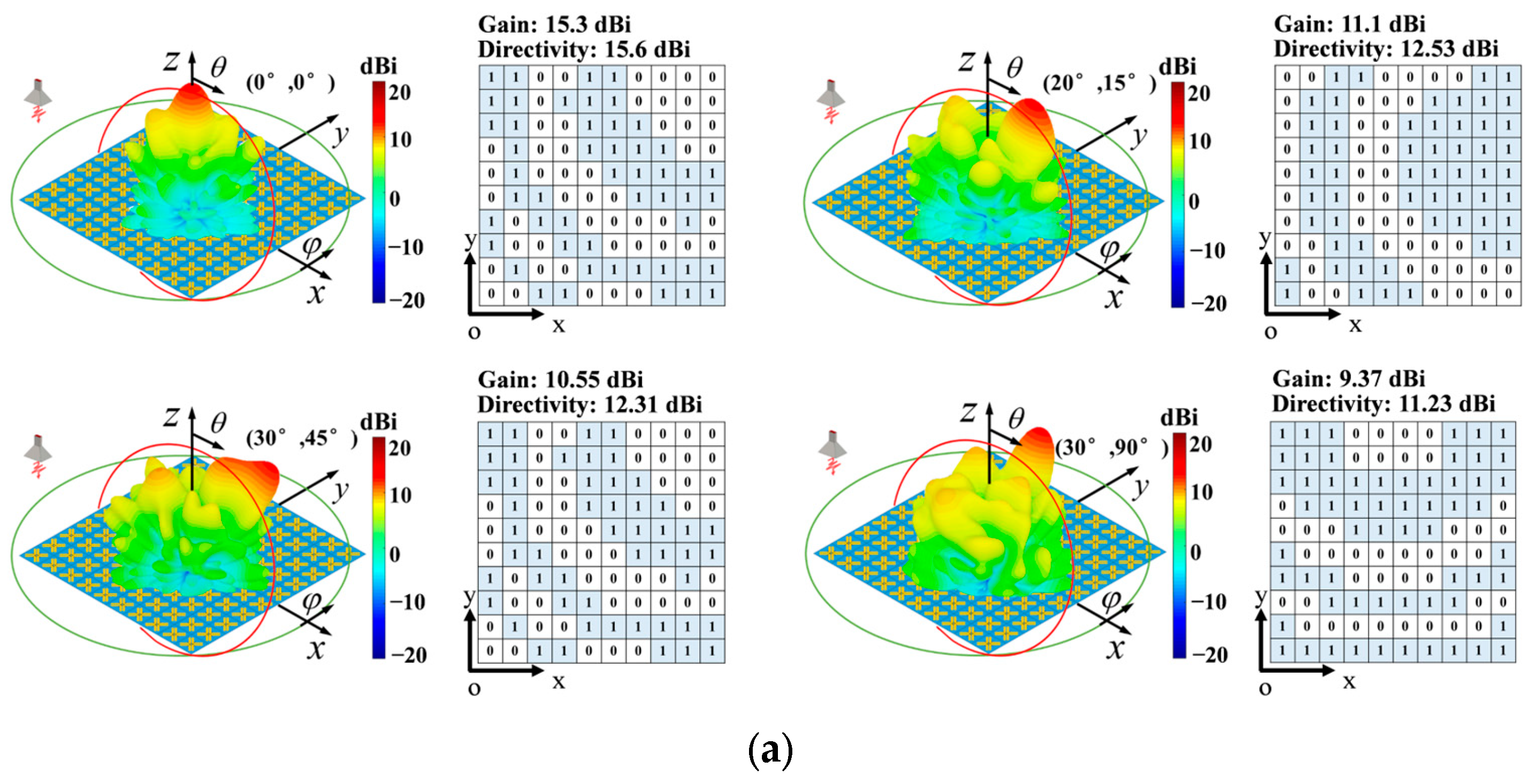
The WR-159 horn antenna (from Pasternack Enterprises, Suzhou, China) was used as a feed source. It was placed right at the center of the metasurface at a distance of 285.3 mm about 5.5 wavelengths at 5.8 GHz to ensure that the incident wave was a plane wave. The total reflected far-field beam patterns in the CP case and CoP case are, respectively, shown in Figure 6a,b, with the beam steering angles , , and .
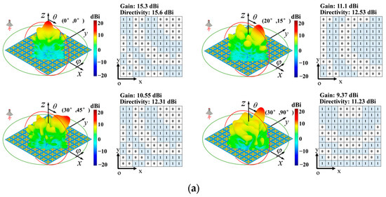

Figure 6.
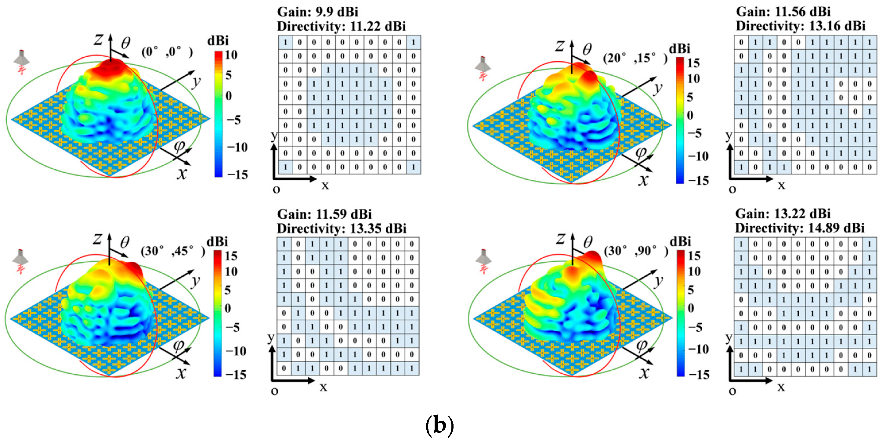
The total reflected far-field at 5.8 GHz shaped in different angles. (a) CP case. (b) CoP case. Near the far-field is the metasurface’s configuration. “0” represents CP1 or CoP1, and “1” illustrates CP2 or CoP2.
In the CP case, the co-polarized reflected wave is very weak, having almost no effect on the total reflected field, and cannot be controlled. Thus, the total reflected field is dominated by cross-polarization reflection waves. At 5.8 GHz, the gains in four steering angles are separately 15.3 dBi, 11.1 dBi, 10.55 dBi and 9.37 dBi, and the corresponding directivities are, respectively, 15.6 dBi, 12.53 dBi, 12.31 dBi and 11.23 dBi. In the CoP case, similar to the CP case, the total reflected field is dominated by co-polarized reflection waves since the cross-polarized reflection wave is weak enough to have no effect on the total reflected field. At 5.8 GHz, the gains in the four steering angles are separately 9.9 dBi, 11.56 dBi, 11.59 dBi and 13.22 dBi, and the corresponding directivities are, respectively, 11.22 dBi, 13.16 dBi, 13.35 dBi and 14.89 dBi. Compared with these two results, we found that the gains and directivities in the CP case are smaller than those in the CoP case. The reason is the reflection loss, as shown in Figure 3, at 5.8 GHz. The losses in CP1 and CP2 are separately −1.2 dB and −1.1 dB, while those in CoP1 and CoP2 are, respectively, −0.78 dB and −0.96 dB. Although the losses in the CP cases are worse than those in the CoP cases at 5.8 GHz, the losses in the CP cases are almost identical and small enough, which is good for the focusing beam and suppressing sidelobes, as shown in Figure 6. Also, during the whole working band, we obtained similar far-field results. However, it is worth mentioning that during the whole operation band, the two losses of the CP cases are always almost the same and small enough, which does not happen in the CoP cases. Especially, for the other frequencies except 5.8 GHz, the losses in the CP cases are better than those in the CoP cases. This means that at other frequencies, the gains and directivities of the CP cases are better than those in the CoP cases, with a better ability to focus the beam and suppress the sidelobe. That is why a beam with low sidelobes can be modulated within the range of the elevation angle in the CP case but can only be steered in and with high sidelobes in the CoP case.
In conclusion, the proposed metasurface achieves a good performance of beam steering in both the CP case and the CoP case. And the cross-polarized reflection field is focused better than the co-polarized reflection field during the whole working band, although the co-polarized wave has a smaller reflection loss at 5.8 GHz.
Also, Figure 6 verifies well that our proposed metasurface has a good synthesis of 1-bit phase difference reflected wave. The produced 1-bit reflected wave can be either totally in-phase or totally out-phase, resulting in either additive synthesis or complete cancellation. After synthesizing these 10 × 10 in-phase or out-phase reflected waves, the total reflected field can be directed toward the desired direction.
Furthermore, as the beam steering angle increases, the beam steering capability decreases since some side lobes appear and increase, which can be improved by increasing the number of unit cells. Of course, as the size of the array increases, the beam steering capability, including the precision and range, will be enhanced as well. However, a larger array means more reflected waves need to be utilized, and more in-phase and out-of-phase wave information must be processed. The reflection process and the determination of the unit cell states take longer. For applications where processing time is not a critical factor, the array size can be determined based on the required accuracy. However, for applications that require rapid processing, the size of the array depends on the allowable processing time.
In addition, we compared our work with other relative publications, as shown in Table 1, and the proposed metasurface features a lower profile and loss, supports multiple polarization conversion, and enables a better beam steering.

Table 1.
Literature comparison and synthesis.
4. Conclusions
In this paper, an electrically tunable reflective metasurface with a low profile, low loss and multiple polarization conversion is proposed. It achieves cross-polarization and co-polarization reflection waves, with the phase of both controlled by 1 bit. These good characteristics give it an advantage in beam steering and shaping since more waves with different polarization can be used at the same time for some purpose. The proposed metasurface is expected to expand some electromagnetic applications, such as wireless communication, radar imaging and wireless power transfer.
Author Contributions
Conceptualization, B.L. and S.L.; Methodology, B.L., Y.W., C.W. and S.L.; Formal analysis, B.L. and S.L.; Investigation, B.L. and S.L.; Data curation, Y.W. and C.W.; Writing—original draft, Y.W.; Writing—review & editing, B.L. and S.L. All authors have read and agreed to the published version of the manuscript.
Funding
This research was funded by the Key Project of National and Local Joint Engineering Laboratory of RF Integration and Micro Assembly Technology, grant number KFJJ20230102; the Ministry of Education and Equipment Development Department, grant number 8091B032224; the Guangdong Basic and Applied Basic Research Foundation, grant numbers 2022A1515110125 and 2024A1515012357; and the Huzhou Key Laboratory of Terahertz Integrated Circuits and Systems, grant number HKLTICY23KF04.
Data Availability Statement
The original contributions presented in the study are included in the article, further inquiries can be directed to the corresponding author.
Conflicts of Interest
The authors declare no conflicts of interest.
References
- Wang, E.W.; Yu, S.J.; Phan, T.; Dhuey, S.; Fan, J.A. Arbitrary Achromatic Polarization Control with Reconfigurable Metasurface Systems. Laser Photonics Rev. 2023, 17, 2200926. [Google Scholar] [CrossRef]
- Shao, L.; Li, Z.; Feng, J.; Zhang, J.; Shi, H.; Bai, X.; Zhu, W. Transmissive Metasurface for Multi-Channel and Full-Polarization Modulation of Electromagnetic Wavefronts. Photonics Res. 2023, 11, 245–251. [Google Scholar] [CrossRef]
- Pramanik, S.; Bakshi, S.C.; Koley, C.; Mitra, D.; Monti, A.; Bilotti, F. Active Metasurface-Based Reconfigurable Polarization Converter with Multiple and Simultaneous Functionalities. IEEE Antennas Wirel. Propag. Lett. 2023, 22, 522–526. [Google Scholar] [CrossRef]
- Baghel, A.K.; Kulkarni, S.S.; Nayak, S.K. Linear-to-Cross-Polarization Transmission Converter Using Ultrathin and Smaller Periodicity Metasurface. IEEE Antennas Wirel. Propag. Lett. 2019, 18, 1433–1437. [Google Scholar] [CrossRef]
- Li, W.; Ma, Q.; Liu, C.; Zhang, Y.; Wu, X.; Wang, J.; Gao, S.; Qiu, T.; Liu, T.; Xiao, Q.; et al. Intelligent Metasurface System for Automatic Tracking of Moving Targets and Wireless Communications Based on Computer Vision. Nat. Commun. 2023, 14, 989. [Google Scholar] [CrossRef] [PubMed]
- Li, S.J.; Han, B.W.; Li, Z.Y.; Liu, X.B.; Huang, G.S.; Li, R.Q.; Cao, X.Y. Transmissive Coding Metasurface with Dual-Circularly Polarized Multi-Beam. Opt. Express 2022, 30, 26362–26376. [Google Scholar] [CrossRef] [PubMed]
- Zhang, K.; Wang, Y.; Burokur, S.N.; Wu, Q. Generating Dual-Polarized Vortex Beam by Detour Phase: From Phase Gradient Metasurfaces to Metagratings. IEEE Trans. Microw. Theory Tech. 2022, 70, 200–209. [Google Scholar] [CrossRef]
- Wang, C.; Pang, M.; Zhong, D.; Cui, Y.; Wang, W. A MmWave Communication Testbed Based on IEEE 802.11ad with Scalable PtMP Configuration. China Commun. 2022, 19, 44–56. [Google Scholar] [CrossRef]
- Xu, B.; Zhou, T.; Gao, F.; Xu, T.; Hu, H. RIS-Aided MIMO Communications: Angle-Dependent Amplitude-Phase Response Model and Capacity Analysis. IEEE Wirel. Commun. Lett. 2024, 14, 290–294. [Google Scholar] [CrossRef]
- Gao, W.H.; Chen, M.; Cheng, Q.; Cui, T.J. A 1-Bit Coding Metasurface with Polarization Conversion in X-Band. Front. Mater. 2022, 9, 914937. [Google Scholar] [CrossRef]
- Shi, H.; Liu, R.; Zhang, Z.; Chen, X.; Wang, L.; Yi, J.; Liu, H.; Zhang, A. A Dual-Polarized Reflective Reconfigurable Metasurface with Stable Amplitude Based on Guided-Wave-Driven Structure. IEEE Antennas Wirel. Propag. Lett. 2024, 23, 1720–1724. [Google Scholar] [CrossRef]
- Hassan, A.G.; Sumaid, M.; Ahmed, F.; Shoaib, N.; Abbasi, Q.H.; Nikolaou, S. Reconfigurable Absorptive and Polarization Conversion Metasurface Consistent for Wide Angles of Incidence. Sci. Rep. 2023, 13, 18209. [Google Scholar] [CrossRef] [PubMed]
- Wang, J.; Shi, H.; Chen, X.; Yi, J.; Chen, J.; Zhang, A.; Liu, H. A Second-Order Cross-Polarization Conversion Metasurface with High Frequency Selectivity. IEEE Antennas Wirel. Propag. Lett. 2023, 22, 3077–3081. [Google Scholar] [CrossRef]
- Cerveny, M.; Ford, K.L.; Tennant, A. Reflective Switchable Polarization Rotator Based on Metasurface with PIN Diodes. IEEE Trans. Antennas Propag. 2021, 69, 1483–1492. [Google Scholar] [CrossRef]
- Yang, H.; Wang, S.C.; Li, P.; He, Y.; Zhang, Y.J. A Broadband Multifunctional Reconfigurable Polarization Conversion Metasurface. IEEE Trans. Antennas Propag. 2023, 71, 5759–5767. [Google Scholar] [CrossRef]
- Liu, W.; Ke, J.C.; Xiao, C.; Zhang, L.; Cheng, Q.; Cui, T.J. Broadband Polarization-Reconfigurable Converter Using Active Metasurfaces. IEEE Trans. Antennas Propag. 2023, 71, 3725–3730. [Google Scholar] [CrossRef]
- Zheng, Q.; Guo, C.; Vandenbosch, G.A.E.; Yuan, P.; Ding, J. Dual-Broadband Highly Efficient Reflective Multi-Polarisation Converter Based on Multi-Order Plasmon Resonant Metasurface. IET Microw. Antennas Propag. 2020, 14, 967–972. [Google Scholar] [CrossRef]
- Chen, Q.; Cheng, Y.F.; Shao, C.H.; Feng, J.; Liao, C.; Ding, X. A High-Gain Dual-Band Shared-Aperture Array Integrating Zero-Order-Resonance Patch and Higher-Order Metasurface Antenna. Sci. Rep. 2023, 13, 11647. [Google Scholar] [CrossRef] [PubMed]
- Chen, H.; Zhao, W.; Gong, X.; Du, L.; Cao, Y.; Zhai, S.; Song, K. Multi-Band High-Efficiency Multi-Functional Polarization Controller Based on Terahertz Metasurface. Nanomaterials 2022, 12, 3189. [Google Scholar] [CrossRef] [PubMed]
- Bo, X.Z.; Chen, H.; Yu, B.Y.; Geng, M.Y.; Liu, Z.G.; Lu, W.B. A Flexible and Transparent Broadband Metasurface Polarization Converter. IEEE Antennas Wirel. Propag. Lett. 2024, 23, 1311–1315. [Google Scholar] [CrossRef]
Disclaimer/Publisher’s Note: The statements, opinions and data contained in all publications are solely those of the individual author(s) and contributor(s) and not of MDPI and/or the editor(s). MDPI and/or the editor(s) disclaim responsibility for any injury to people or property resulting from any ideas, methods, instructions or products referred to in the content. |
© 2025 by the authors. Licensee MDPI, Basel, Switzerland. This article is an open access article distributed under the terms and conditions of the Creative Commons Attribution (CC BY) license (https://creativecommons.org/licenses/by/4.0/).