Article

Polarization Compensation and Multi-Branch Fusion Network for UAV Recognition with Radar Micro-Doppler Signatures

1
Radar Technology Research Institute, School of Information and Electronics, Beijing Institute of Technology, Beijing 100081, China
2
Advanced Technology Research Institute, Beijing Institute of Technology, Jinan 250300, China
*
Author to whom correspondence should be addressed.
Remote Sens. 2025, 17(22), 3693; https://doi.org/10.3390/rs17223693
Submission received: 7 October 2025 / Revised: 5 November 2025 / Accepted: 11 November 2025 / Published: 12 November 2025

Highlights

What are the main findings?
  • A rotor–polarization coupling model and corresponding compensation algorithm are developed to correct time-varying polarization rotation induced by UAV rotor motion, effectively enhancing harmonic visibility and micro-Doppler continuity under low-SNR conditions.
  • A Multi-branch Polarization-Aware Fusion Network (MPAF-Net) integrating U-Net-based denoising, polarization-compensated feature extraction, and multi-head attention fusion achieves over 5% improvement in UAV recognition accuracy compared with conventional polarimetric representations.
What is the implication of the main finding?
  • The proposed framework significantly improves the stability and discriminability of UAV polarimetric micro-Doppler features, offering a practical solution for cluttered, low-SNR radar environments.
  • The results contribute to the advancement of polarization-based recognition techniques for rotor-type UAVs, enhancing radar sensing capability for small aerial vehicles.

Abstract

Polarimetric radar offers strong potential for UAV detection, but time-varying polarization induced by rotor rotation leads to unstable echoes, degrading feature consistency and recognition accuracy. This paper proposes a unified framework that combines rotor phase compensation, adaptive polarization filtering, and a multi-branch polarization aware fusion network (MPAF-Net) to enhance micro-Doppler features. The compensation scheme improves harmonic visibility through rotation-angle-based phase alignment and polarization optimization, while MPAF-Net exploits complementary information across polarimetric channels for robust classification. The framework is validated on both simulated and measured UAV radar data under varying SNR conditions. Results show an average harmonic SNR gain of approximately 1.2 dB and substantial improvements in recognition accuracy: at 0 dB, the proposed method achieves 66.7% accuracy, about 10% higher than Pauli and Sinclair decompositions, and at 20 dB, it reaches 97.2%. These findings confirm the effectiveness of the proposed approach for UAV identification in challenging radar environments.

1. Introduction

The widespread use of unmanned aerial vehicles (UAVs) in civilian applications has raised concerns over unauthorized flights. Due to differences in payload capacity, UAVs pose varying levels of threat, making accurate target recognition of small UAVs an urgent challenge [1,2].
Radar, due to its advantage in long-range detection, is one of the most effective means for UAV surveillance [3,4]. Existing research on UAV model identification primarily relies on micro-Doppler signatures. Some studies extract key micro-Doppler characteristics—such as differences in rotor speeds [5]—to accomplish model identification. Other researchers generate time-frequency spectrograms or cadence-velocity diagrams and apply machine learning methods, such as convolutional neural networks (CNNs), to achieve high classification accuracy in radar-based Doppler classification tasks [6,7,8,9]. Nevertheless, micro-Doppler-based approaches have inherent limitations: when the target is at a long distance or the UAV’s orientation changes with respect to the radar’s single-polarization beam, signal attenuation can significantly degrade the distinguishability of these features [10,11].
Polarimetric radar technology has been successfully applied in meteorological monitoring for several decades. By analyzing the target’s polarimetric scattering matrix, a variety of polarimetric features have been proposed to facilitate classification tasks involving precipitation, insects, and birds [12,13,14]. In the field of remote sensing, numerous studies have applied various polarimetric decomposition techniques to classify land cover types in synthetic aperture radar (SAR) imagery [15,16,17,18]. However, the potential of polarimetric radar for UAV model recognition remains underexplored. Some studies have examined the radar cross-section (RCS) of static UAVs under different polarizations for classification [19], and further analyzed how incident angle affects the micro-Doppler features in different polarization channels for moving UAVs [20]. Real-data experiments have also assessed the contribution of polarimetric parameters to recognition performance [21], and recent work has incorporated polarization-domain spectral representations into CNN-based classification frameworks [22].
However, existing studies have largely overlooked the time-varying polarimetric characteristics induced by UAV rotor rotation. To address this gap, we propose a comprehensive framework that combines physical-model-based compensation with deep learning–driven feature fusion for UAV recognition. First, a polarization rotation model is constructed to characterize the periodic modulation caused by rotor motion. By compensating for the rotor-phase-dependent polarization variation, enhanced micro-Doppler signatures are obtained through optimal polarimetric vector extraction. On this basis, we further design a Multi-branch Polarization Aware Fusion Network (MPAF-Net) to exploit the complementary information across multiple polarization channels. Specifically, the network adopts a dual-branch structure: one branch performs denoising and detail recovery from raw polarimetric spectrograms, while the other focuses on discriminative feature extraction from polarization-compensated spectrograms. Cross-branch parameter interaction and multi-head attention fusion are employed to achieve consistent and robust joint representations, which are subsequently used for UAV model recognition. Both simulation and measurement experiments validate the proposed framework: Monte Carlo simulations show that the compensation method improves harmonic signal-to-noise ratio (SNR), while real radar data demonstrate clearer micro-Doppler signatures and notable gains in recognition accuracy compared with conventional polarimetric representations such as Pauli RGB and Sinclair decompositions.

2. Materials and Methods

2.1. Modeling of Polarization Rotation Angle

To support polarization-domain feature extraction for UAV type recognition, it is necessary to characterize the influence of rotor motion on the polarization state. This section constructs a geometric model that maps the rotor blade rotation angle to the resulting polarization rotation angle. The relevant coordinate system and vector projection relationships are illustrated in Figure 1, which provides a visual reference for the subsequent derivations.
A global Cartesian coordinate system is defined, where the X-axis points to geographic east, the Y-axis to the north, and the Z-axis is perpendicular to the horizontal plane, pointing upward toward the sky. The radar’s boresight azimuth and elevation angles are denoted by α and β , respectively. It is assumed that the rotor plane of the UAV is approximately parallel to the ground during flight, such that the radar’s elevation angle β directly corresponds to the UAV’s pitch angle. In this setup, the azimuth angle α = 0 is aligned with the vertical polarization ( V ) direction. Based on these definitions, the unit vectors for horizontal polarization ( H ), vertical polarization ( V ), and the radar line-of-sight direction ( L ) are given by:
H = sin α , cos α , 0 , V = sin β cos α , sin β sin α , cos β , L = cos β cos α , cos β sin α , sin β .
To facilitate further modeling, the rotor blade rotation angle ϕ is defined as:
ϕ = ω t + φ 0 ,
where ω is the angular velocity and φ 0 is the initial phase. The estimation of ω will be discussed in Section 2.2. According to the right-hand rule, the unit vector n D representing the blade rotation direction, which is perpendicular to the rotation plane, is defined in the global coordinate system as:
n D = cos ϕ , sin ϕ , 0 .
As shown in Figure 1, the projection of n D onto the polarization plane is denoted by n pro and obtained by subtracting its component along the radar line-of-sight direction:
n pro = n D n D · L L .
The polarization rotation angle θ is defined as the angle between the normalized projection of the blade vector and the H-polarization direction:
θ = arccos n pro n pro · H .
Since the analytical expression of θ becomes overly complicated due to its nonlinear dependence on multiple parameters, we refrain from presenting the full expansion and instead focus on its numerical evaluation in subsequent analysis.
Once the polarization rotation angle θ is obtained, the influence of this rotation on the scattering matrix can be modeled. The polarization scattering matrix S 0 characterizes the target’s intrinsic scattering properties in its own reference coordinate system, and is typically defined as:
S 0 = S HH S HV S VH S VV ,
where S p q denotes the complex scattering amplitude from polarization q to polarization p ( p , q { h , v } ). For a symmetric target with scattering matrix S 0 , the rotated scattering matrix S ( θ ) is expressed as:
S ( θ ) = R ( θ ) S 0 R T ( θ ) ,
where R ( θ ) is the 2D polarization rotation matrix:
R θ = cos θ sin θ sin θ cos θ .

2.2. Estimation of UAV Rotor Rotational Speed

For a rotor with N blades, each blade has a distinct initial phase angle ϕ 0 , n p q = ϕ p + 2 π n / N , where n = 1 , 2 , , N . To accurately estimate the UAV blade rotational speed ω , a time-domain signal model [23] of the UAV was first established and is expressed as follows:
s t = k = 1 K A k exp j 4 π λ R T k t + p = 1 P q = 1 Q n = 1 N B p q exp j 4 π λ R n p q t ,
R n p q t R T p r n p q cos β cos ω t + ϕ 0 n p q ,
where K is the number of scattering centers on the UAV main body, A k is the complex amplitude of the k-th scattering center, P is the number of rotors, Q is the number of scattering centers per blade, B p q is the complex amplitude of the q-th scattering center on the p-th rotor, R T k t is the distance between the radar and the k-th scattering center on the UAV main body, R T p t is the distance between the radar and the center of the p-th rotor, r n p q is the distance between the q-th scattering center on the n-th blade and the center of the p-th rotor, and β is the angle between the UAV and the horizontal plane. Finally, the UAV signal model can be simplified as a linear superposition of the UAV main body translation and the rotor translation plus micro-motion.
Based on the rotor-related component in the UAV micro-Doppler signal model, a nonlinear compensation algorithm is proposed. The algorithm mainly consists of phase differencing and a two-dimensional search compensation based on rotor size and rotor frequency. The detailed procedure is extensively discussed in [24], and here we highlight only the key steps.
In the phase differencing process, the UAV radar echo is first transformed to the frequency domain, where the zero-frequency bin is set to zero to suppress the main Doppler component. After inverse FFT back to the time domain, the signal is multiplied by its complex conjugate delayed by a time interval Δ t to obtain phase differences. This shifts most of the main Doppler energy to zero frequency for removal, while preserving harmonic components. One harmonic term is then selected as a compensation factor to enhance their SNR.
Subsequently, a two-dimensional search compensation is applied to the differenced time-domain signal to obtain the compensated feature map. The ranges of target rotor size and rotor frequency are set as A 0 , A max and ω 0 , ω max , respectively. The expression for the compensation factor H A f t is given by:
H A f t = exp j 4 π A λ · cos ω t + exp j 4 π A λ · cos ω t + ω Δ t .
Finally, inspired by the concept of the Radon transform [25,26,27], the differenced signal is projected onto the rotor parameter plane by traversing all candidate rotor sizes and frequencies. By extracting the frequency corresponding to the strongest response, the blade rotation frequency ω can be determined.
ω opt = arg max ω s ( A , ω ) · H A f ( t ) d t

2.3. Compensation of Blade Phase

The UAV rotor blades are approximately modeled as rotating thin ellipsoids, whose polarimetric scattering characteristics are highly sensitive to their instantaneous orientation. In particular, the initial azimuthal phase of UAV blades is unknown and must be estimated, as it directly influences the observed polarimetric signatures. Based on the directional sensitivity of thin ellipsoid scattering, we assume that different initial phases lead to variations in polarimetric energy distribution. Specifically, when the cross-polarization (HV) energy reaches a minimum, it is considered that the blade’s polarization-aligned reflection is maximized. Therefore, the initial phase parameter φ 0 is exhaustively searched within the range 0 , 2 π to identify this condition.
Once the estimated rotation angle θ ( t ) of the target is obtained, the polarimetric scattering vectors s ( t ) for each radar pulse are compensated by applying an inverse rotation:
s comp ( t ) = R ( θ ( t ) ) s ( t ) R ( θ ( t ) ) .
After inverse rotation compensation and removal of the main Doppler component in the frequency domain, the average energy of the HV channel is computed under each candidate initial phase. When the HV energy reaches its minimum, it indicates that the phase differences across pulses have been effectively aligned. Consequently, the averaged polarimetric covariance matrix at this point better captures the dominant scattering characteristics of the UAV rotor.
The optimal initial phase φ 0 * is determined by minimizing the total HV channel energy after compensation:
φ 0 * = arg min φ 0 [ 0 , 2 π ] t R ( θ ( t ) ) s ( t ; φ 0 ) R ( θ ( t ) ) HV 2 .
To compensate for the polarization scattering variations caused by blade rotation, the main Doppler components in each polarization channel are first suppressed in the frequency domain. This step ensures that the subsequent polarization feature extraction is not biased by the dominant translational motion of the UAV.
Under the reciprocity condition, the normalized scattering vector k L , which characterizes the target’s scattering response across polarization channels and is based on the Pauli decomposition, is defined as:
k L = S H H , 2 S H V , S V V T .
The polarization covariance matrix is constructed by averaging the instantaneous outer product over several pulses, yielding
C mean = E k L ( t ) · k L H ( t ) ,
which is then subjected to eigenvalue decomposition:
C mean = U Λ U H ,
where Λ = diag λ 1 , λ 2 , λ 3 , U = v 1 , v 2 , v 3 . The eigenvector v 3 associated with the largest eigenvalue λ 3 is selected as the optimal polarization feature vector, as it maximizes the signal energy in the polarization domain.
The final compensated UAV signal is obtained by projecting the original polarization echo signal s ( t ) onto this optimal vector:
s rot ( t ) = k L ( t ) · v 3 T .
This one-dimensional sequence is then subjected to short-time Fourier transform (STFT) to generate a polarization-compensated time-frequency spectrogram, which enhances the visibility of micro-Doppler signatures.
To summarize, the optimization problem can be formulated as:
v opt = arg max v , v = 1 v H C mean v ,
where v opt = v 3 is the eigenvector corresponding to the largest eigenvalue of C mean .

2.4. CNN-Based UAV Recognition

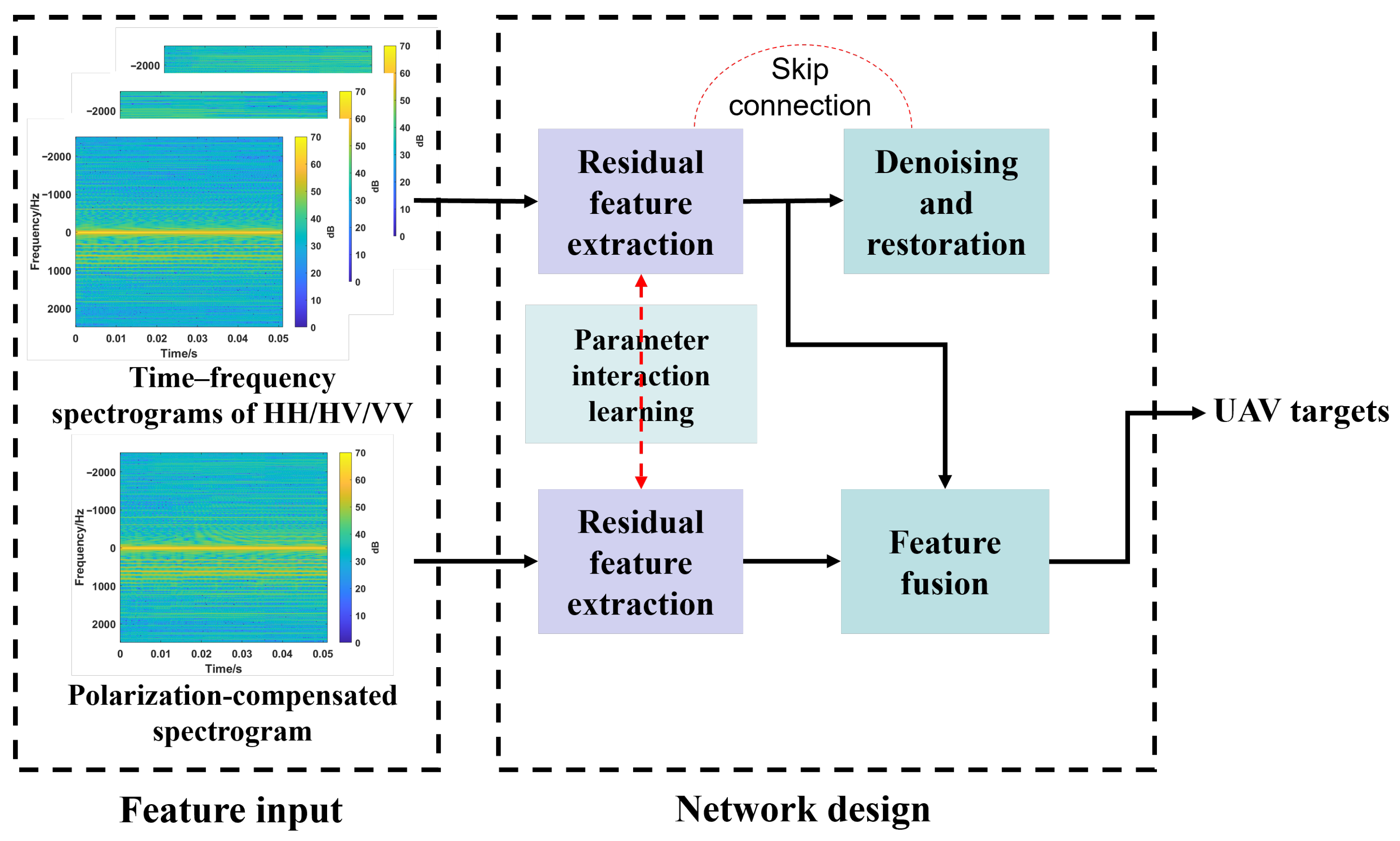
To fully exploit the complementary information across polarimetric channels for UAV recognition and to enhance the discriminability of polarimetric micro-Doppler features under low-SNR conditions, this work proposes a Multi-branch Polarization Aware Fusion Network (MPAF-Net), as illustrated in Figure 2. The network adopts a dual-input, dual-path cooperative design. The upper branch takes the original tri-polarized (HH/HV/VV) spectrograms as input and focuses on denoising and signal recovery, while the lower branch processes polarization-compensated spectrograms and emphasizes discriminative feature extraction. Information exchange between the two branches is achieved through parameter interaction at multiple semantic levels, and a multi-head attention fusion module at higher layers integrates global contextual information to form a unified representation for UAV type recognition.
Let the input data be X noisy R C × T × F , X pc R 1 × T × F , where C = 3 corresponds to the HH/HV/VV polarimetric channels, and T and F denote the slow-time and frequency dimensions, respectively. Here, X noisy represents the noisy tri-polarization spectrograms, while X pc denotes the enhanced spectrograms obtained through the aforementioned polarization rotation compensation.
The proposed MPAF-Net consists of four key components: (i) a U-Net encoder–decoder framework for multi-channel denoising and detail reconstruction; (ii) a polarization-compensated feature subnetwork for extracting stable and discriminative polarimetric time–frequency representations; (iii) a cross-branch parameter interaction mechanism for mid-level semantic sharing and modulation; and (iv) a multi-head attention (MHA) fusion module for high-level integration of cross-channel and time–frequency information. The network is trained in an end-to-end manner by jointly minimizing reconstruction loss and recognition loss, thereby enabling cooperative optimization of visibility enhancement and class discrimination.

2.4.1. U-Net-Based Denoising of UAV Polarimetric Time–Frequency Features

To address issues such as fragmented micro-Doppler streaks and weak harmonic visibility caused by strong clutter and low SNR in measured environments, the upper branch adopts a U-Net structure [28] to perform multi-scale denoising and reconstruction on the noisy input X noisy R C × T × F , where C = 3 corresponds to the HH/HV/VV polarimetric channels, and T and F denote the slow-time and frequency dimensions, respectively.
Compared with the conventional U-Net, the encoder incorporates residual convolutional blocks from ResNet-18 [29] to improve gradient propagation and feature representation. The mapping of the l-th encoder layer is formulated as
h l = ϕ BN ( Conv 3 × 3 ( h l 1 ) ) + h l 1 ,
where h l R D l × T l × F l denotes the feature map of the l-th layer, ϕ ( · ) is a nonlinear activation function (ReLU in this work), BN ( · ) is batch normalization, and Conv 3 × 3 represents a 3 × 3 convolution operation. The residual connection mitigates vanishing gradients and promotes feature reuse. Downsampling is implemented via strided convolutions or max pooling ( MaxPool ), allowing the encoder to capture semantic information at multiple time–frequency scales.
In the decoder, transposed convolutions ( Deconv 3 × 3 ) are used for progressive upsampling, while skip connections concatenate features from the corresponding encoder layers to restore high-resolution details:
h ˜ l 1 = ϕ BN ( Deconv 3 × 3 ( h ˜ l ) ) h l 1 ,
where h ˜ l 1 denotes the reconstructed feature of the ( l 1 ) -th decoder layer, and ‖ indicates feature concatenation along the channel dimension.
The final reconstructed spectrogram is denoted as X ^ den R C × T × F . To explicitly preserve micro-Doppler streaks and harmonic details, the reconstruction loss is defined in a structure-preserving form:
L rec = α X ^ den X clean 1 + ( 1 α ) 1 SSIM X ^ den , X clean ,
where X clean is a reference clean spectrogram obtained from high-SNR samples, · 1 denotes the L 1 norm, SSIM ( · , · ) is the structural similarity index, and α ( 0 , 1 ) balances pixel-level fidelity and structural preservation.
This reconstruction constraint enhances the contrast and continuity between fundamental and harmonic components, making the micro-Doppler structures more distinguishable for subsequent branches and fusion modules.

2.4.2. Interactive Learning for Polarimetric Deep Feature Extraction

The lower branch takes the polarization-compensated spectrogram X pc R 1 × T × F as input and extracts robust discriminative features. The output of the m-th residual block is denoted by z m R d m × T m × F m , where d m is the feature channel dimension. To enable effective information exchange between the two branches, a hybrid mechanism combining parameter interaction and feature modulation is proposed as follows.
(1)
Partial Weight Sharing
Convolutional kernels at corresponding semantic levels in the upper and lower branches are partially shared:
W m top λ s W m top + ( 1 λ s ) W m bottom ,
where W m top and W m bottom represent the convolutional weights of the m-th layer in the upper and lower branches, respectively, and λ s [ 0 , 1 ] controls the degree of sharing. This strategy establishes parameter-level alignment between the two branches, encouraging them to learn consistent representations of temporal–frequency patterns such as rotor cycles and harmonic spacing.
(2)
Feature-Wise FiLM Modulation
At the m-th layer, the lower branch generates a modulation pair ( γ m , β m ) that adjusts the upper-branch feature map h m as:
h ˜ m = γ m ( z m ) h m + β m ( z m ) ,
where ⊙ denotes element-wise (channel-wise) multiplication, and γ m ( · ) , β m ( · ) are learnable affine transformations derived from z m . This Feature-wise Linear Modulation (FiLM) [30] allows the polarization-compensated branch to conditionally modulate the denoising branch, adaptively emphasizing or suppressing micro-Doppler patterns based on the estimated rotor phase and polarization stability.
(3)
Cross-Branch Consistency Regularization
To prevent feature drift between branches, a semantic-level consistency constraint is imposed on the globally averaged pooled (GAP) features:
L cons = m GAP ( h m ) GAP ( z m ) 2 2 ,
where GAP ( · ) performs spatial averaging over ( T m , F m ) , and · 2 denotes the Euclidean norm. This term aligns the semantic centers of both branches while maintaining their complementary roles.

2.4.3. Multi-Head Attention Enhanced Feature Fusion

After reconstruction and interaction, two high-level feature maps H , Z R D × T × F are obtained. Dimensionality reduction is first performed using 1 × 1 convolutions, and the results are concatenated as
U = Concat ϕ ( Conv 1 × 1 ( H ) ) , ϕ ( Conv 1 × 1 ( Z ) ) R D × T × F .
Treating the ( T × F ) locations as a sequence of tokens, the query, key, and value matrices are computed as
Q = U W Q , K = U W K , V = U W V ,
where W Q , W K , W V R D × d k are learnable projection matrices. The output of the h-th attention head is given by
head h = Softmax Q h K h d k V h ,
and the fused representation is obtained by concatenating all H heads and applying a linear projection:
F mha = Concat ( head 1 , , head H ) W O ,
where W O R H d k × D is the output projection matrix.
The multi-head attention (MHA) mechanism [31] captures both global dependencies across polarization channels and local continuity in time–frequency regions, thereby linking fundamental and harmonic components within the spectrogram. The fused representation F mha is used for classification via a fully connected (FC) layer followed by a softmax activation:
L cls = c = 1 K y c log p ^ c ,
where K denotes the number of UAV categories, y c is the one-hot encoded ground truth, and p ^ c is the predicted class probability.
The overall training objective combines reconstruction, consistency, and classification losses:
L total = λ 1 L rec + λ 2 L cons + λ 3 L cls ,
where λ 1 , 2 , 3 > 0 are weighting coefficients controlling the contribution of each term.
This end-to-end joint optimization enables the upper branch to learn cleaner and more continuous tri-polarization spectrograms, while the lower branch acquires stable and discriminative polarization-compensated representations. Through global fusion via multi-head attention, the network achieves enhanced noise robustness and improved UAV recognition accuracy under low-SNR conditions.

3. Results and Discussion

3.1. Experimental Validation via Simulation

The full-polarization frequency response of a typical quadrotor UAV was simulated using Feko software, employing radar parameters consistent with the system introduced in Section 3.3. In the simulation scenario, the UAV rotor speed is set to 2500 rpm. Each transmitted pulse corresponds to an angular increment of approximately 11 . 99 , which is approximated by a simulation step of 12 . A total of 30 steps are completed to cover one full rotor revolution. The geometric structure and material parameters of the UAV are listed in Table 1. Specifically, the fuselage is made of PC/ABS (20% ABS), while the rotor blades are composed of PA6 reinforced with 30% glass fiber (GF).
The electromagnetic simulation is carried out using the Multi-Level Fast Multipole Method (MLFMM), which is an accelerated solver based on the Method of Moments (MoM). This method is particularly suitable for electrically large problems, as it significantly reduces computational complexity while maintaining high accuracy.
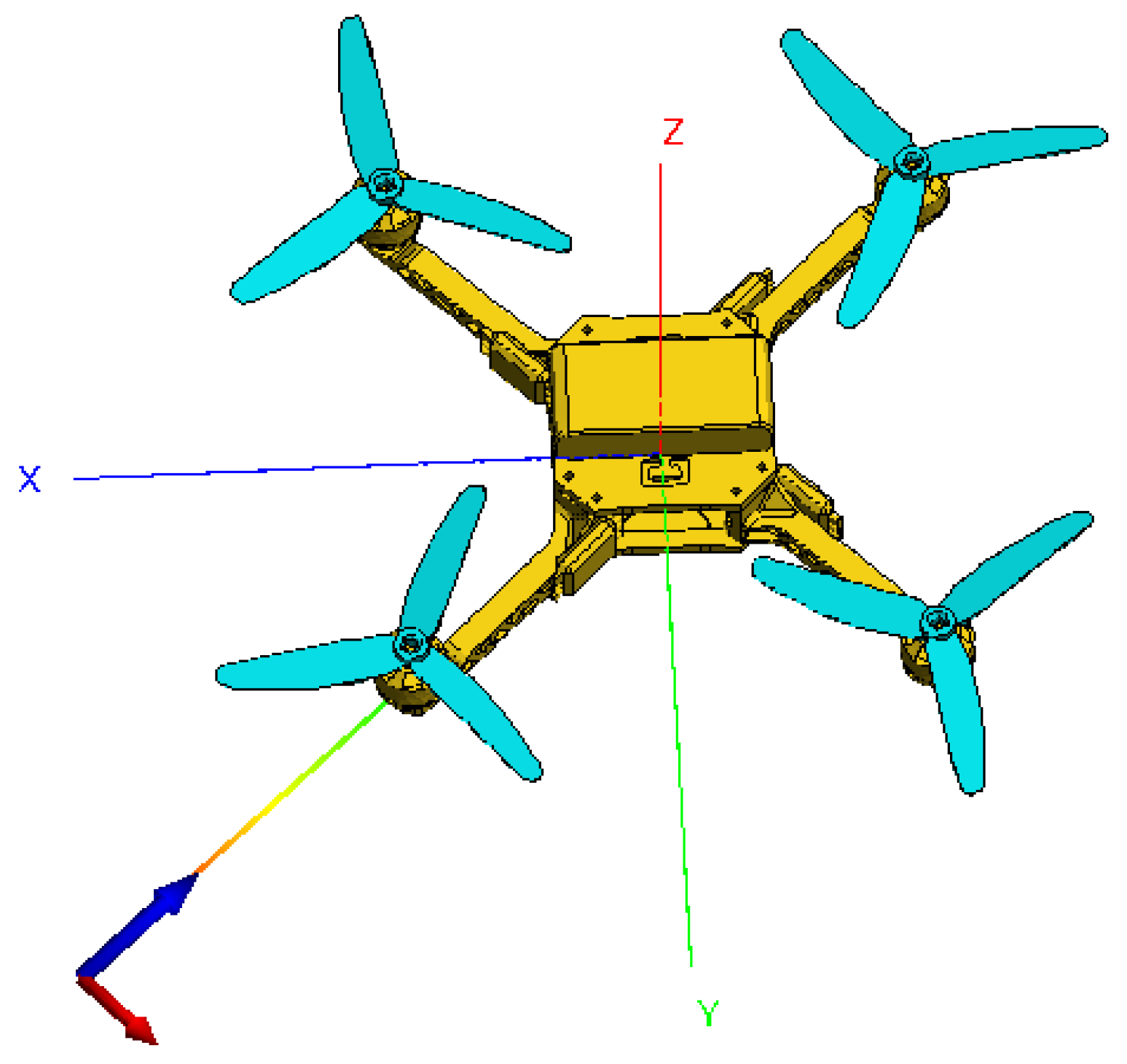
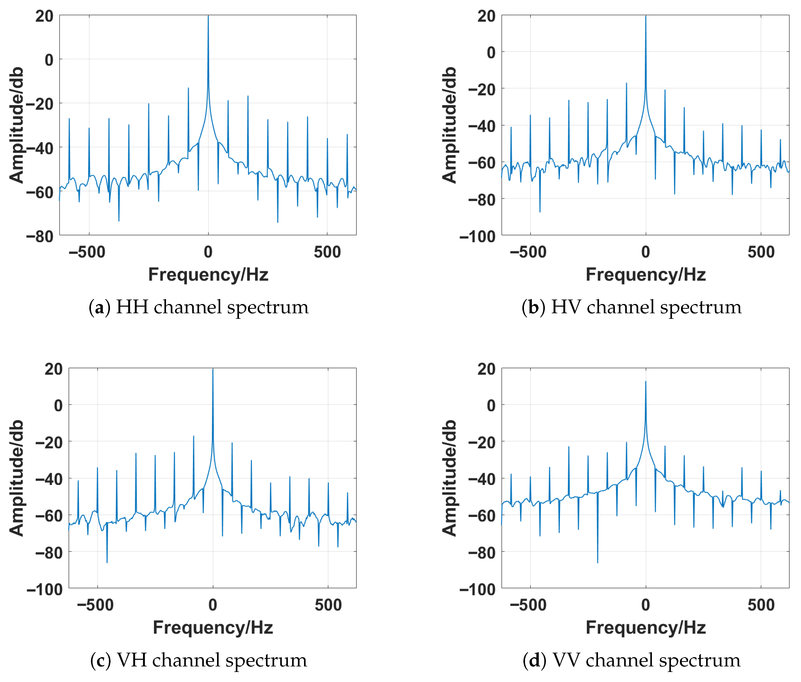
The 3D electromagnetic simulation model of the UAV is shown in Figure 3. The UAV is assumed to move at a constant velocity along the negative x-axis, starting from the initial position ( 2.3 , 2 , 0.3 ) km. The flight velocity is set to 20 m/s with an altitude of 3 km. Under these conditions, a fully polarimetric echo sequence with a duration of 0–0.432 s is generated, from which Doppler spectra are extracted for subsequent performance analysis. The Doppler spectra of different polarization channels are presented in Figure 4.
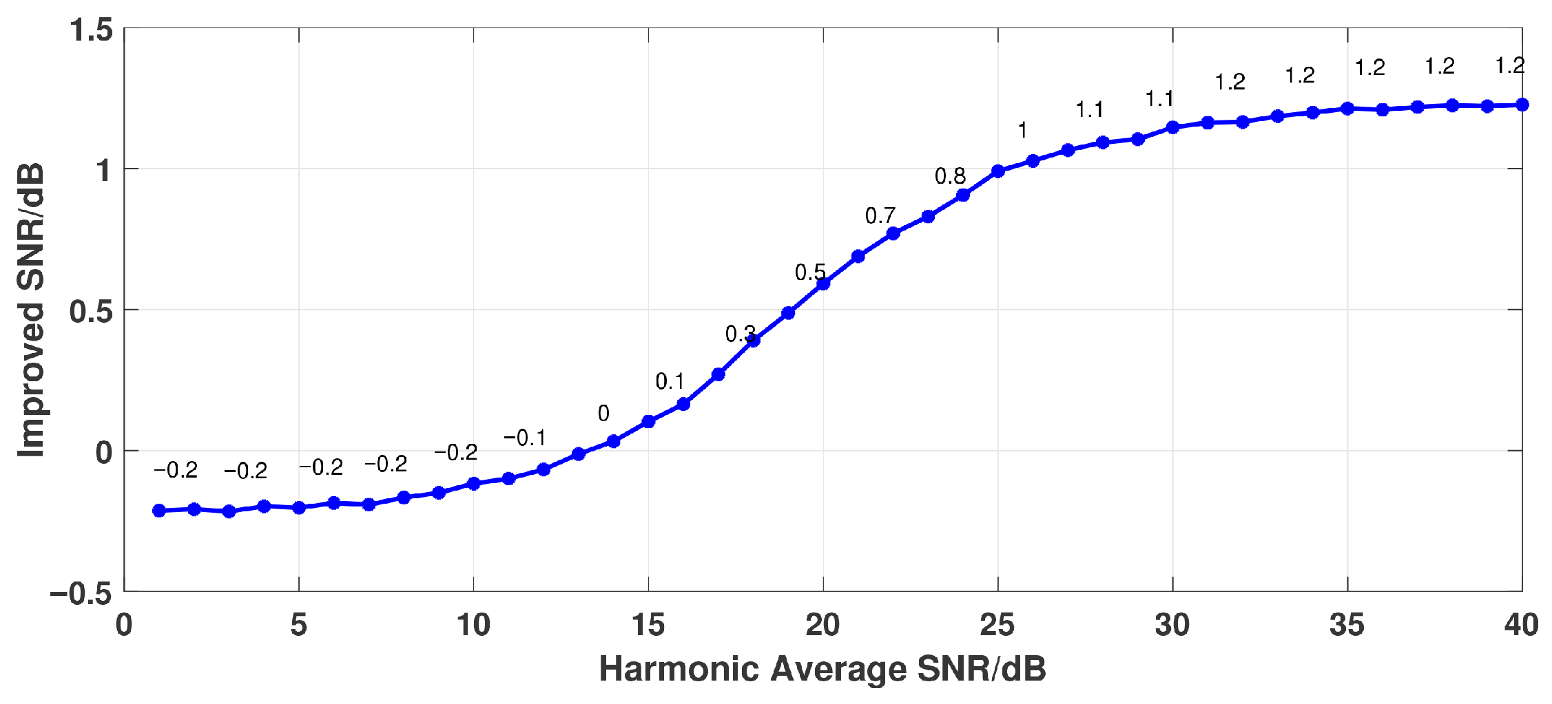
To evaluate the algorithm’s performance under different noise conditions, Monte Carlo simulations were conducted with 1000 iterations per signal-to-noise ratio (SNR) level. As shown in Figure 5, the proposed optimization method demonstrates a clear performance gain when the harmonic SNR exceeds approximately 15 dB. The enhancement becomes more pronounced with increasing SNR, reaching a maximum SNR improvement of 1.2 dB at 40 dB harmonic SNR. These results verify the effectiveness and robustness of the algorithm in improving the visibility of micro-Doppler features.

3.2. Measured Data Acquisition

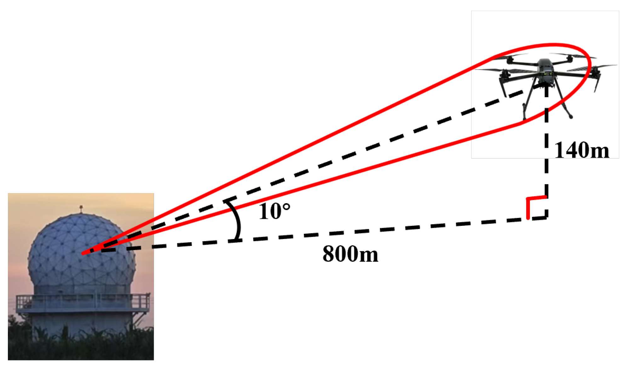
In order to construct a comprehensive radar database covering multiple UAV models and various flight states, a large-scale field experiment was conducted in Dongying, Shandong Province, in February 2023. The objective was to acquire high-resolution, fully-polarimetric, and multi-angle radar echo data to support subsequent research on UAV target recognition techniques. The experiment employed a high-resolution cooperative radar measurement system as the core platform [32], in combination with a high-resolution phased array scanning radar and a high-resolution fully-polarimetric tracking radar. Through cooperative control, these radars jointly accomplished target search, localization, and precise tracking. During the experiment, the phased array radar was primarily responsible for wide-area surveillance. Once a UAV target was detected, its position information was immediately transmitted to the fully-polarimetric radar, which then performed multi-channel tracking and collected high-resolution polarimetric data. The conceptual illustration of the polarimetric data acquisition scenario is shown in Figure 6, where the UAV is located near its initial position after takeoff. To ensure accurate data annotation, an electro-optical video tracking system was also incorporated, enabling synchronized monitoring and video recording of the UAV flight process.The key radar parameters are summarized in Table 2.
This experiment involved eight UAV models, including six quadrotors (DJI-M300, DJI-Air2S, DJI-Phantom 4, DJI-Mini2, DJI-Mavic3, and LYZRC), one hexacopter (DJI-M600), and one ducted quadrotor (DJI-Avata), as illustrated in Figure 7. These UAVs differ significantly in terms of weight, rotor dimensions, aerodynamic structure, and maximum flight speed, thereby representing the diversity of radar scattering characteristics of UAV targets. Figure 8 illustrates the Doppler spectrum distributions of a representative UAV across the four polarization channels (HH, HV, VH, VV). Taking the DJI-M300 as an example, one can clearly observe the presence of the main Doppler peak along with several harmonic components, which correspond to the micro-Doppler effects induced by rotor modulation.
To simulate motion features in complex low-altitude environments, six representative flight modes were designed for each UAV, namely: fixed mode (hovering), multi-azimuth mode, multi-elevation mode, longitudinal mode, tangential mode, and fast maneuvering mode. The corresponding motion parameters and durations are summarized in Table 3. Specifically, the fixed mode was used to acquire steady-state echoes, with hovering lasting approximately one minute. The multi-azimuth mode simulated circular horizontal flights at different angles, performed at 2 m/s for one minute. The multi-elevation mode involved vertical ascent to 500 m followed by descent, with a total duration of about one minute, aiming to analyze the impact of altitude variation on radar echoes. The longitudinal and tangential modes consisted of uniform linear flights along trajectories parallel or perpendicular to the radar beam, each lasting one minute before returning to the starting point. Finally, the fast maneuvering mode simulated dynamic environments through rapid random turns, high-speed approaching, and receding maneuvers, with a duration of approximately one minute. The radar returns were segmented into 512-pulse slices (approximately 0.1 s), yielding over 1600 samples per UAV type.

3.3. Experimental Results and Analysis

In this section, the proposed polarization compensation and feature enhancement framework is comprehensively validated using measured UAV radar data. The analysis begins with an examination of the signal-to-noise ratio (SNR) characteristics of the main and harmonic Doppler components across multiple UAV types, revealing the polarimetric differences between co- and cross-polarized channels. To further assess the robustness of the method under practical low-SNR conditions, controlled complex Gaussian noise is injected into the measured data, and polarization compensation is applied to enhance micro-Doppler continuity. Finally, classification experiments are conducted under different harmonic SNR levels to evaluate recognition performance, thereby demonstrating the effectiveness and generalization capability of the proposed framework in complex noise environments.

3.3.1. Main Doppler SNR Analysis

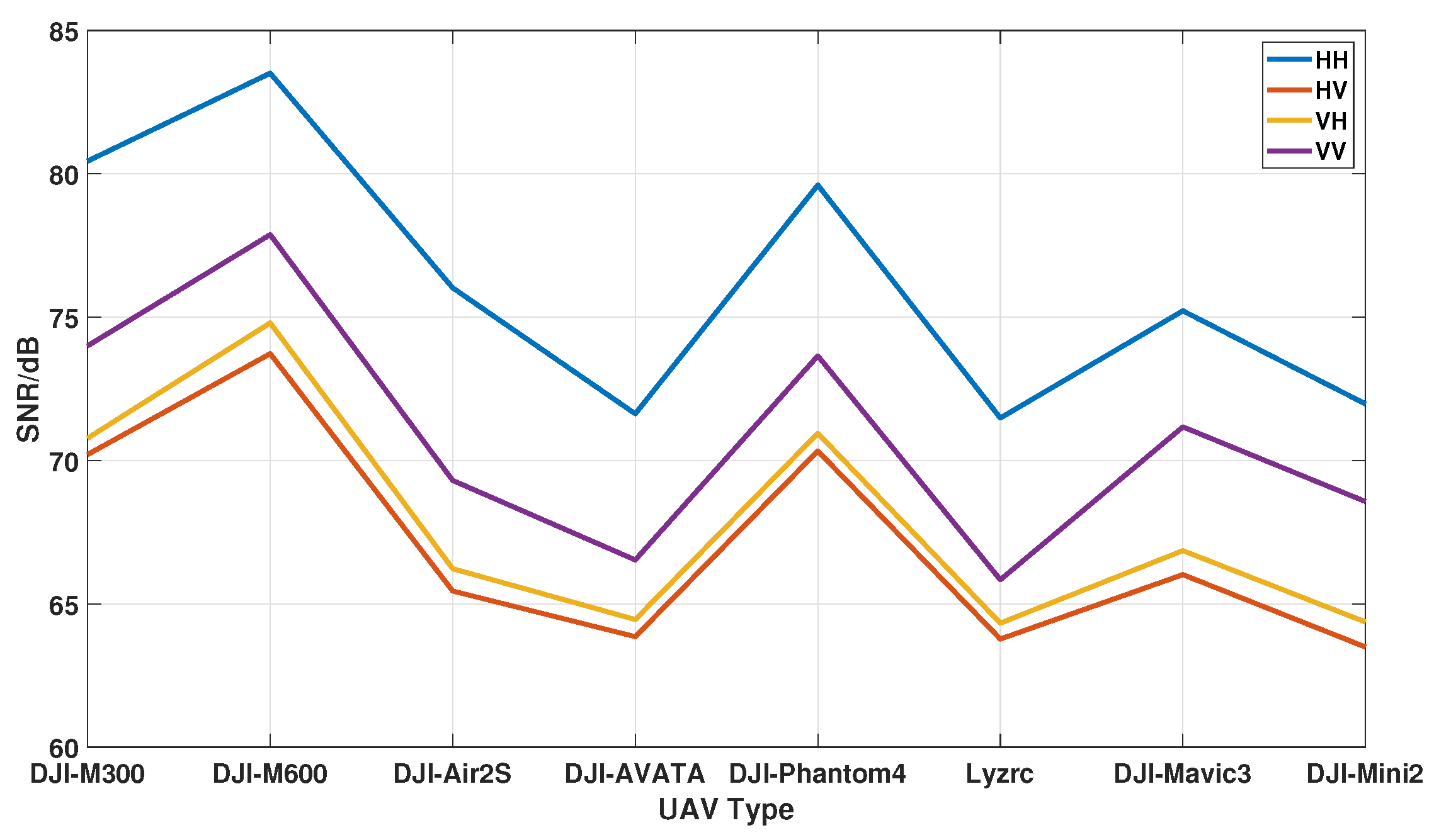
The signal-to-noise ratios (SNRs) of the main Doppler components were first analyzed across eight UAV types. As shown in Table 4 and Figure 9, the main Doppler SNR remains consistently high (63–83 dB). Co-polarized channels (HH, VV) provide the highest SNR values, while cross-polarized channels (HV, VH) are relatively weaker. For example, the DJI-M600 achieves the highest main Doppler SNR of 83.24 dB in the HH channel, which can be attributed to its large rotor size and strong radar cross-section. Overall, these results indicate that co-polarized channels contribute most significantly to UAV detection and tracking.

3.3.2. Harmonic SNR Analysis

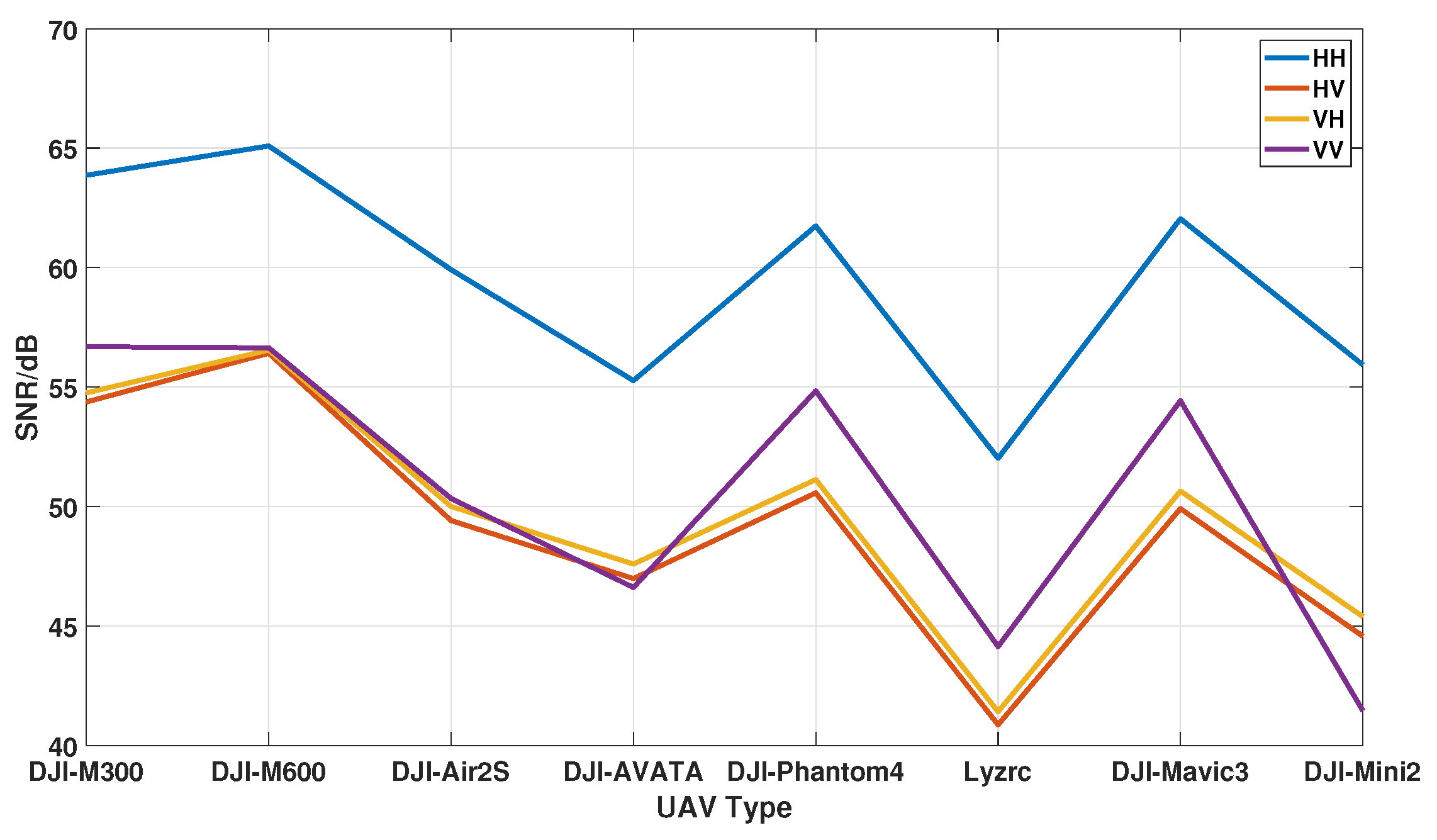
The harmonic SNR reflects the visibility of rotor-modulated micro-Doppler features. Table 5 and Figure 10 show that harmonic SNRs are generally lower than main Doppler SNRs, ranging from 41 to 65 dB. The DJI-M600 again exhibits the strongest harmonic energy (64.92 dB in HH), while smaller UAVs such as the DJI-Avata show much weaker harmonic SNRs, particularly in cross-polarized channels (as low as 40.59 dB for Lyzrc-L100 in HV). These results confirm that co-polarized channels provide clearer and more stable harmonic signatures, while cross-polarized harmonics are more susceptible to noise.

3.3.3. Noise Injection and Compensation Analysis

To simulate low-SNR conditions, complex Gaussian white noise was added to the measured echoes. To ensure fair evaluation across different UAV models within the same range conditions, the statistical characteristics of the DJI-M300 were used as a reference baseline. All UAV datasets were contaminated with noise of the same magnitude as that applied to the M300, which may result in relatively lower SNRs for smaller UAVs but guarantees consistent noise levels for comparison under equivalent distance conditions. The procedure is as follows: (1) estimate the average harmonic SNR of DJI-M300 ( P sig 63 dB, as summarized in Table 5); (2) generate zero-mean, unit-variance complex Gaussian noise; (3) compute the scaling coefficient:
β = P sig P noise · 10 SNR target / 10 ,
  • (4) construct the noisy signal as
    X noisy = X clean + β N κ pol .
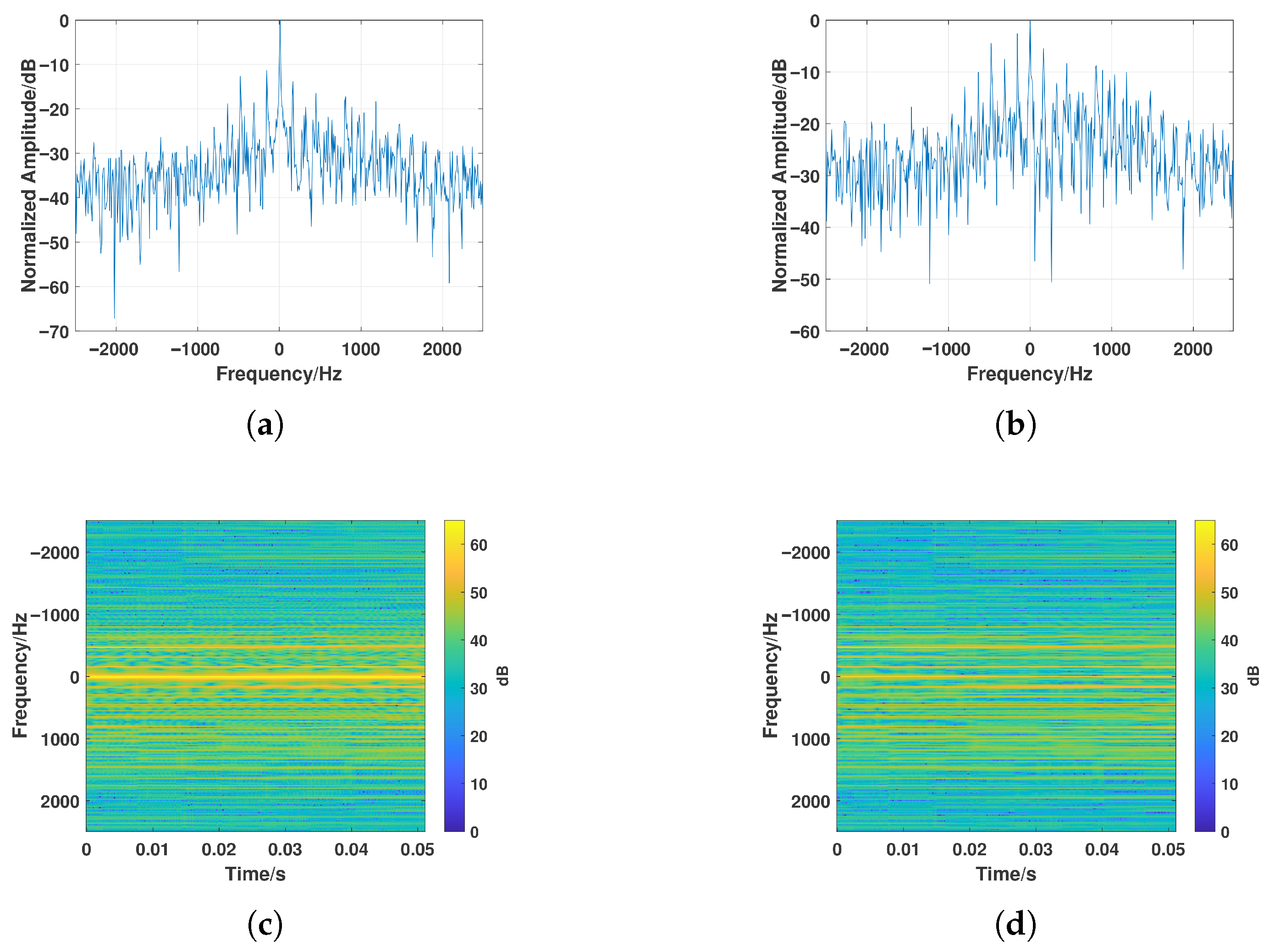
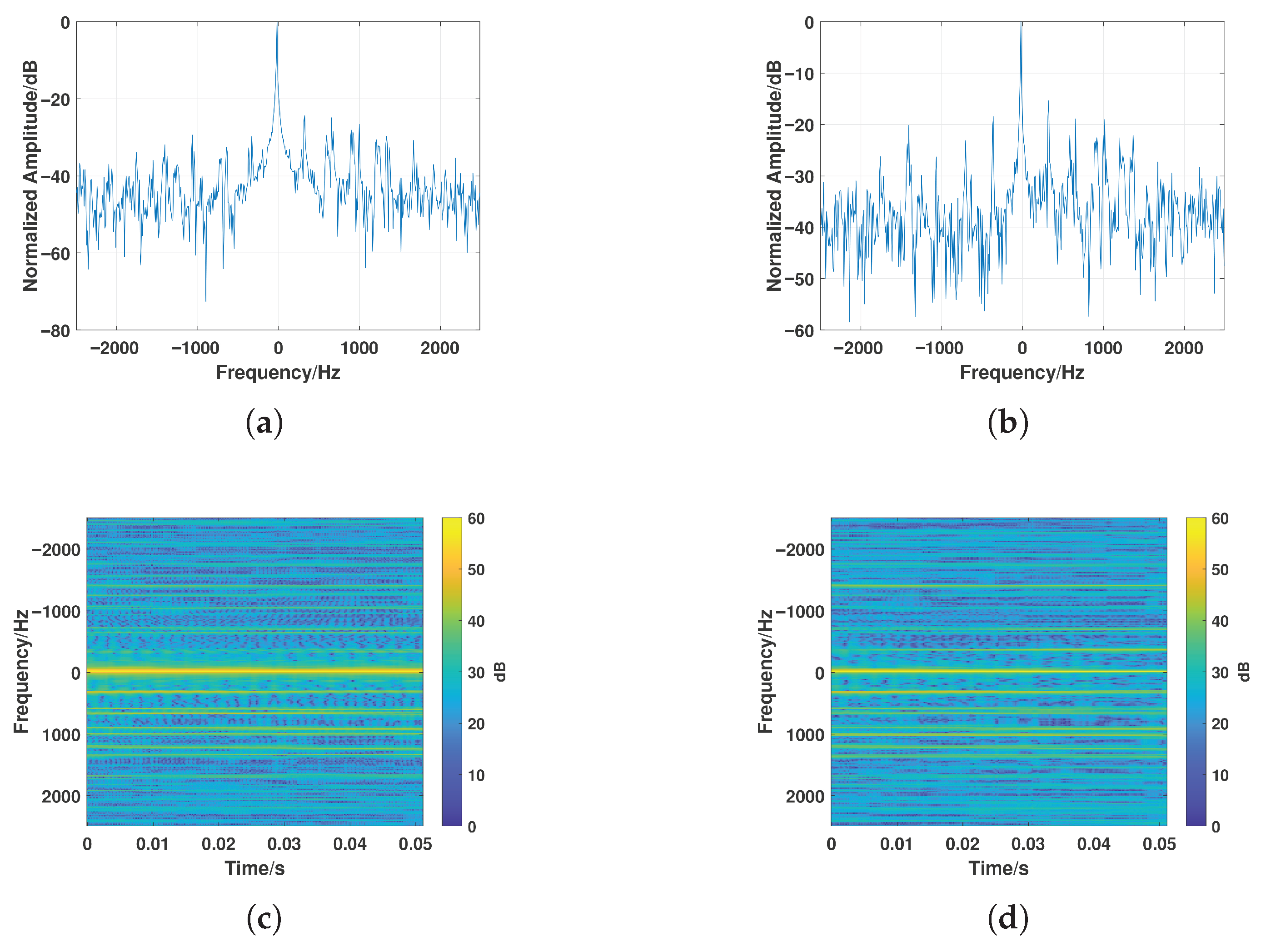
Figure 11, Figure 12 and Figure 13 illustrates the comparison of amplitude spectra and spectrograms before and after polarization compensation. The analysis is conducted on measured UAV data with an average harmonic SNR of approximately 20 dB. We evaluate the compensation performance on UAVs of different sizes, including the DJI-M300, DJI-Mavic3 and DJI-Mini, to verify the generality of the method across varying rotor dimensions and micro-Doppler bandwidths. Across all platforms, the compensated results exhibit an average SNR improvement of about 2 dB, leading to clearer harmonic traces and more continuous periodic micro-Doppler signatures, thereby demonstrating consistent enhancement under diverse UAV configurations.

3.3.4. Classification Performance

To further evaluate recognition performance, the enhanced spectrograms were input to a CNN-based classifier. Following the standard protocol in [22], the radar returns were segmented into 512-pulse slices (approximately 0.1 s). For each UAV type, more than 1600 slices were obtained and randomly divided into training and testing sets at an 8:2 ratio, resulting in 1280 training samples per class. The classifier adopts a ResNet-18 backbone [29], which provides efficient deep feature extraction while maintaining low complexity, making it suitable for radar-based classification tasks.
The network was trained on a NVIDIA RTX A6000 GPU provided by PNY Technologies, based in Parsippany-Troy Hills, New Jersey, USA. The implementation employed PyTorch (version 1.11.0+cu113) in conjunction with the CUDA 12.4 toolkit. Network parameters were optimized using the Adam algorithm, with a momentum factor of 0.9. Training was conducted for 1000 epochs, initially using a learning rate of 0.001, which was reduced by half if the loss did not improve over 10 consecutive epochs. A batch size of 16 was adopted throughout training.
(1) Ablation Study on Fusion Strategies
To justify the design choices of the proposed MPAF-Net, we conducted an ablation study that compares the dual-branch architecture with partial weight sharing and FiLM modulation against several alternative fusion strategies. Specifically, the following variants were evaluated:
  • Single-Branch (SB): A baseline model where the U-Net reconstruction and polarization-compensated feature extraction are merged into a single processing branch without explicit feature interaction.
  • Early Fusion (EF): The three polarimetric spectrograms are concatenated at the input level and fed into a single deep network, corresponding to early fusion of polarization cues.
  • Late Fusion (LF): Independent networks are trained for the U-Net reconstruction and the compensated feature extraction, and their features are fused at the classifier layer.
  • Proposed MPAF-Net: The full framework with dual-branch structure, partial weight sharing, and FiLM modulation.
Table 6 reports the recognition accuracy under different harmonic SNR conditions. The single-branch and early fusion models perform poorly at 0 dB due to insufficient separation of denoising and discriminative feature extraction tasks. Late fusion improves robustness but lacks fine-grained cross-branch alignment. Removing FiLM modulation leads to a 2–4% accuracy drop, confirming its role in adaptively transferring polarization-stable harmonic cues. The full MPAF-Net achieves the best and most stable performance under all SNR conditions.
(2) Comparative Evaluation with Existing Polarimetric Approaches
To comprehensively evaluate the effectiveness of the proposed method, several input configurations and representative baselines from prior studies were compared. Specifically, (1) single-channel spectrograms (HH, HV, VV) were first used as basic references [33]. (2) Conventional polarimetric descriptors (e.g., polarization ratio, co-/cross-polarization contrast, and Cloude–Pottier decomposition parameters) were extracted from the time–frequency domain and fed into a Support Vector Machine (SVM) classifier [21]. This represents the widely used feature-engineering + shallow model paradigm in polarimetric UAV recognition. (3) Conventional polarimetric representations, including Pauli RGB and Sinclair decompositions [34], were implemented following standard linear-channel combination strategies widely adopted in polarimetric micro-Doppler analysis. These approaches reflect commonly used feature enhancement techniques in the literature. (4) The proposed framework, which jointly incorporates rotor-induced polarization compensation and U-Net-based spectrogram reconstruction, was then evaluated under identical conditions.
The classification accuracies obtained under different harmonic SNR levels (0, 10, and 20 dB) are summarized in Table 7. The comparison highlights how the proposed method improves recognition performance particularly in low-SNR environments, where micro-Doppler harmonic visibility is crucial for discrimination.
Several conclusions can be drawn:
  • Single-channel HH and VV inputs achieve over 91% accuracy at 20 dB but drop to about 40% at 0 dB, revealing strong noise sensitivity.
  • Sinclair and Pauli fusions improve over single-channel results, particularly at 0 dB with a gain of about 14%, confirming the complementary nature of multi-polarimetric features.
  • The proposed compensation + U-Net method achieves 66.7% accuracy at 0 dB, about 10% higher than the best baseline. At 10 dB and 20 dB, it further reaches 88.6% and 97.2%, maintaining superior performance across all SNR conditions.
  • Performance-Complexity Trade-off: It is noteworthy that at a high SNR of 20 dB, the performance gain of the proposed method over the "Compensated" baseline is marginal. This indicates that the added computational complexity of the deep network may not be fully justified in high-SNR environments. The primary advantage of the proposed method is its significant performance improvement in low-SNR regimes (e.g., 0–10 dB), which are often more challenging and critical for practical applications. This trade-off should be considered when deploying the method in scenarios with varying noise conditions.
Overall, the proposed framework significantly enhances harmonic visibility and micro-Doppler continuity in low-SNR conditions, enabling deep networks to capture more discriminative features. These results demonstrate the robustness and generalization ability of the method, providing a feasible solution for UAV recognition in complex interference environments.

4. Conclusions

This paper presents a comprehensive framework for UAV recognition that integrates rotor phase compensation, adaptive polarization filtering, and a multi-branch polarization aware fusion network (MPAF-Net). The proposed signal processing scheme enhances harmonic visibility and continuity, while the network architecture fully exploits complementary information across polarimetric channels. Extensive evaluations, including both simulation and real measurement data under varying SNR conditions, demonstrate that the framework achieves an average harmonic SNR gain of about 1.2 dB and delivers consistent improvements in recognition accuracy over conventional methods. These results validate the effectiveness of combining polarization compensation with deep feature fusion, offering a robust solution for UAV type recognition in low-SNR radar environments.

Author Contributions

Conceptualization, L.W. and Z.C.; methodology, L.W., Z.C., T.Y., Y.Y., J.C. and R.W.; investigation, L.W.; resources, R.W., T.Y. and Z.C.; data curation, L.W., Z.C., Y.Y. and J.C.; writing original draft preparation, L.W.; writing review and editing, R.W., T.Y., Z.C., J.C. and Y.Y. All authors have read and agreed to the published version of the manuscript.

Funding

This work was supported in part by the Key R&D Program of Shandong Province, China under Grant 2025CXGC010209 and in part by the National Natural Science Foundation of China under Grant 62201049 and in part by the Shandong Provincial Natural Science Foundation, China (ZR2022QF073).

Data Availability Statement

In this paper, we have established a UAV dataset based on a high-resolution radar system. However, due to the difficulty in data acquisition, we do not plan to make the dataset publicly available at this time.

Acknowledgments

The authors have reviewed and edited the output and take full responsibility for the content of this publication.

Conflicts of Interest

The authors declare no conflicts of interest.

Abbreviations

The following abbreviations are used in this manuscript:
MPAF-NetMulti-branch polarization aware fusion network
UAVunmanned aerial vehicles
SNRsignal-to-noise ratio
CNNconvolutional neural network
SARsynthetic aperture radar
RCSradar cross-section
STFTshort-time Fourier transform
MHAmulti-head attention
GFglass fiber
MLFMMMulti-Level Fast Multipole Method
MOMMethod of Moments
FiLMFeature-wise Linear Modulation

References

  1. Ahmad, B.I.; Rogers, C.; Harman, S.; Dale, H.; Jahangir, M.; Antoniou, M.; Baker, C.; Newman, M.; Fioranelli, F. A Review of Automatic Classification of Drones Using Radar: Key Considerations, Performance Evaluation, and Prospects. IEEE Aerosp. Electron. Syst. Mag. 2024, 39, 18–33. [Google Scholar] [CrossRef]
  2. Rahman, M.H.; Sejan, M.A.S.; Aziz, M.A.; Tabassum, R.; Baik, J.I.; Song, H.K. A Comprehensive Survey of Unmanned Aerial Vehicles Detection and Classification Using Machine Learning Approach: Challenges, Solutions, and Future Directions. Remote Sens. 2024, 16, 879. [Google Scholar] [CrossRef]
  3. Coluccia, A.; Parisi, G.; Fascista, A. Detection and Classification of Multirotor Drones in Radar Sensor Networks: A Review. Sensors 2020, 20, 4172. [Google Scholar] [CrossRef] [PubMed]
  4. Wang, C.; Tian, J.; Cao, J.; Wang, X. Deep Learning-Based UAV Detection in Pulse-Doppler Radar. IEEE Trans. Geosci. Remote Sens. 2022, 60, 1–12. [Google Scholar] [CrossRef]
  5. Yan, J.; Hu, H.; Gong, J.; Kong, D.; Li, D. Exploring Radar Micro-Doppler Signatures for Recognition of Drone Types. Drones 2023, 7, 280. [Google Scholar] [CrossRef]
  6. Björklund, S. Target Detection and Classification of Small Drones by Boosting on Radar Micro-Doppler. In Proceedings of the 2018 15th European Radar Conference (EuRAD), Madrid, Spain, 26–28 September 2018; pp. 182–185. [Google Scholar] [CrossRef]
  7. Kim, B.K.; Kang, H.S.; Park, S.O. Drone Classification Using Convolutional Neural Networks with Merged Doppler Images. IEEE Geosci. Remote Sens. Lett. 2017, 14, 38–42. [Google Scholar] [CrossRef]
  8. Brooks, D.A.; Schwander, O.; Barbaresco, F.; Schneider, J.Y.; Cord, M. Temporal Deep Learning for Drone Micro-Doppler Classification. In Proceedings of the 2018 19th International Radar Symposium (IRS), Bonn, Germany, 20–22 June 2018; pp. 1–10. [Google Scholar] [CrossRef]
  9. Ma, X.; Oh, B.S.; Sun, L.; Toh, K.A.; Lin, Z. EMD-Based Entropy Features for micro-Doppler Mini-UAV Classification. In Proceedings of the 2018 24th International Conference on Pattern Recognition (ICPR), Beijing, China, 20–24 August 2018; pp. 1295–1300. [Google Scholar] [CrossRef]
  10. Li, T.; Wen, B.; Tian, Y.; Li, Z.; Wang, S. Numerical Simulation and Experimental Analysis of Small Drone Rotor Blade Polarimetry Based on RCS and Micro-Doppler Signature. IEEE Antennas Wirel. Propag. Lett. 2019, 18, 187–191. [Google Scholar] [CrossRef]
  11. Herschfelt, A.; Birtcher, C.R.; Gutierrez, R.M.; Rong, Y.; Yu, H.; Balanis, C.A.; Bliss, D.W. Consumer-grade drone radar cross-section and micro-Doppler phenomenology. In Proceedings of the 2017 IEEE Radar Conference (RadarConf), Seattle, WA, USA, 8–12 May 2017; pp. 981–985. [Google Scholar] [CrossRef]
  12. Jatau, P.; Melnikov, V.; Yu, T.Y. A Machine Learning Approach for Classifying Bird and Insect Radar Echoes with S-Band Polarimetric Weather Radar. J. Atmos. Ocean. Technol. 2021, 38, 1797–1812. [Google Scholar] [CrossRef]
  13. Melnikov, V.M.; Lee, R.R.; Langlieb, N.J. Resonance Effects Within S-Band in Echoes From Birds. IEEE Geosci. Remote Sens. Lett. 2012, 9, 413–416. [Google Scholar] [CrossRef]
  14. Gauthreaux, S.; Diehl, R. Discrimination of Biological Scatterers in Polarimetric Weather Radar Data: Opportunities and Challenges. Remote Sens. 2020, 12, 545. [Google Scholar] [CrossRef]
  15. Cloude, S.; Pottier, E. A review of target decomposition theorems in radar polarimetry. IEEE Trans. Geosci. Remote Sens. 1996, 34, 498–518. [Google Scholar] [CrossRef]
  16. Jin, L.; Qi-hua, W.; Xiao-Feng, A.; Shun-Ping, X. Experimental Study on Full-Polarization Micro-Doppler of Space Precession Target in Microwave Anechoic Chamber. In Proceedings of the 2016 Sensor Signal Processing for Defence (SSPD), Edinburgh, UK, 22–23 September 2016; pp. 1–5. [Google Scholar] [CrossRef]
  17. Liu, X.; Jiao, L.; Tang, X.; Sun, Q.; Zhang, D. Polarimetric Convolutional Network for PolSAR Image Classification. IEEE Trans. Geosci. Remote Sens. 2019, 57, 3040–3054. [Google Scholar] [CrossRef]
  18. Guan, T.; Chang, S.; Deng, Y.; Xue, F.; Wang, C.; Jia, X. Oriented SAR Ship Detection Based on Edge Deformable Convolution and Point Set Representation. Remote Sens. 2025, 17, 1612. [Google Scholar] [CrossRef]
  19. Ezuma, M.; Anjinappa, C.K.; Funderburk, M.; Guvenc, I. Radar Cross Section Based Statistical Recognition of UAVs at Microwave Frequencies. IEEE Trans. Aerosp. Electron. Syst. 2022, 58, 27–46. [Google Scholar] [CrossRef]
  20. Kim, S.; Lee, H.; Noh, Y.H.; Yook, J.G. Polarimetric micro-doppler signature measurement of a small drone and its resonance phenomena. J. Electromagn. Waves Appl. 2021, 35, 1493–1510. [Google Scholar] [CrossRef]
  21. Torvik, B.; Olsen, K.E.; Griffiths, H. Classification of Birds and UAVs Based on Radar Polarimetry. IEEE Geosci. Remote Sens. Lett. 2016, 13, 1305–1309. [Google Scholar] [CrossRef]
  22. Kim, B.K.; Kang, H.S.; Lee, S.; Park, S.O. Improved Drone Classification Using Polarimetric Merged-Doppler Images. IEEE Geosci. Remote Sens. Lett. 2021, 18, 1946–1950. [Google Scholar] [CrossRef]
  23. Kang, K.B.; Choi, J.H.; Cho, B.L.; Lee, J.S.; Kim, K.T. Analysis of Micro-Doppler Signatures of Small UAVs Based on Doppler Spectrum. IEEE Trans. Aerosp. Electron. Syst. 2021, 57, 3252–3267. [Google Scholar] [CrossRef]
  24. Wang, R.; Wang, L.; Cai, J.; Yan, Y.; Jiao, L.; Hu, C. Intelligent Recognition of a Low-altitude UAV Based on Micro-Doppler Feature Enhancement. IEEE Trans. Aerosp. Electron. Syst. 2025, 1–16. [Google Scholar] [CrossRef]
  25. Xu, J.; Yu, J.; Peng, Y.N.; Xia, X.G. Radon-Fourier Transform for Radar Target Detection, I: Generalized Doppler Filter Bank. IEEE Trans. Aerosp. Electron. Syst. 2011, 47, 1186–1202. [Google Scholar] [CrossRef]
  26. Xu, J.; Yu, J.; Peng, Y.N. Radon-Fourier Transform for Radar Target Detection (II): Blind Speed Sidelobe Suppression. IEEE Trans. Aerosp. Electron. Syst. 2011, 47, 2473–2489. [Google Scholar] [CrossRef]
  27. Yu, J.; Xu, J.; Peng, Y.N.; Xia, X.G. Radon-Fourier Transform for Radar Target Detection (III): Optimality and Fast Implementations. IEEE Trans. Aerosp. Electron. Syst. 2012, 48, 991–1004. [Google Scholar] [CrossRef]
  28. Ronneberger, O.; Fischer, P.; Brox, T. U-Net: Convolutional Networks for Biomedical Image Segmentation. arXiv 2015, arXiv:1505.04597. [Google Scholar] [CrossRef]
  29. He, K.; Zhang, X.; Ren, S.; Sun, J. Deep Residual Learning for Image Recognition. In Proceedings of the 2016 IEEE Conference on Computer Vision and Pattern Recognition (CVPR), Las Vegas, NV, USA, 27–30 June 2016; pp. 770–778. [Google Scholar] [CrossRef]
  30. Perez, E.; Strub, F.; de Vries, H.; Dumoulin, V.; Courville, A.C. FiLM: Visual Reasoning with a General Conditioning Layer. arXiv 2017, arXiv:1709.07871. [Google Scholar] [CrossRef]
  31. Vaswani, A.; Shazeer, N.; Parmar, N.; Uszkoreit, J.; Jones, L.; Gomez, A.N.; Kaiser, L.; Polosukhin, I. Attention Is All You Need. arXiv 2023, arXiv:1706.03762. [Google Scholar] [CrossRef]
  32. Hu, C.; Yan, Y.; Wang, R.; Jiang, Q.; Cai, J.; Li, W. High-resolution, multi-frequency and full-polarization radar database of small and group targets in clutter environment. Sci. China Inf. Sci. 2023, 66, 227301. [Google Scholar] [CrossRef]
  33. Park, D.; Lee, S.; Park, S.; Kwak, N. Radar-Spectrogram-Based UAV Classification Using Convolutional Neural Networks. Sensors 2021, 21, 210. [Google Scholar] [CrossRef]
  34. Lee, J.S.; Pottier, E. Polarimetric Radar Imaging: From Basics to Applications; CRC Press: Boca Raton, FL, USA, 2009. [Google Scholar] [CrossRef]
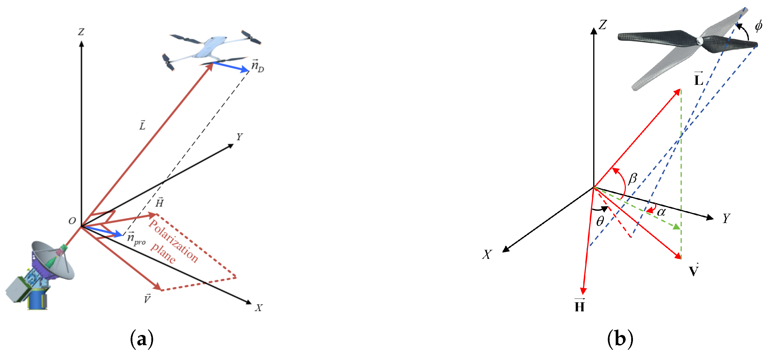
Figure 1. UAV 3D alignment and projection diagram. (a) Vector projection relationships of the UAV body. (b) Geometric relationship between rotor rotation angle and polarization rotation angle.
Remotesensing 17 03693 g001
Figure 2. Schematic of the overall MPAF-Net architecture. The upper branch performs denoising and reconstruction of the tri-polarization time–frequency spectrograms, while the lower branch extracts features from polarization-compensated spectrograms. Mid-level parameter interaction enables collaborative learning, and high-level multi-head attention fuses the representations for final classification.
Remotesensing 17 03693 g002
Figure 3. Electromagnetic simulation model of a typical quadrotor UAV.
Remotesensing 17 03693 g003
Figure 4. Fully polarimetric simulated Doppler spectra of the UAV.
Remotesensing 17 03693 g004
Figure 5. SNR improvement versus average SNR of the first ten harmonic components.
Remotesensing 17 03693 g005
Figure 6. Scenario of UAV Polarimetric Data Acquisition.
Remotesensing 17 03693 g006
Figure 7. Photographs of the UAV models used in the experiment.
Remotesensing 17 03693 g007
Figure 8. Full-polarization Doppler spectra of the DJI-M300 UAV across four polarization channels.
Remotesensing 17 03693 g008
Figure 9. Statistics of main Doppler SNR for different UAVs.
Remotesensing 17 03693 g009
Figure 10. Statistics of harmonic SNR for different UAVs.
Remotesensing 17 03693 g010
Figure 11. Comparison of DJI-M300 amplitude spectra and spectrograms. (a) HH polarization spectrum before compensation. (b) Spectrum after compensation. (c) Time–frequency spectrogram before compensation. (d) Spectrogram after compensation.
Remotesensing 17 03693 g011
Figure 12. Comparison of DJI-Mavic3 amplitude spectra and spectrograms. (a) HH polarization spectrum before compensation. (b) Spectrum after compensation. (c) Time–frequency spectrogram before compensation. (d) Spectrogram after compensation.
Remotesensing 17 03693 g012
Figure 13. Comparison of DJI-Mini amplitude spectra and spectrograms. (a) HH polarization spectrum before compensation. (b) Spectrum after compensation. (c) Time–frequency spectrogram before compensation. (d) Spectrogram after compensation.
Remotesensing 17 03693 g013
Table 1. UAV model geometry and material settings.
ParameterValue
Model origin coordinates[0, 0, 0]
Fuselage dimensions (L × W × H)30 cm × 25 cm × 10 cm
Number of blades2
Fuselage materialPC/ABS (20% ABS)
Rotor materialPA6 + 30%GF
Mesh accuracyCoarse
Table 2. Radar parameters.
ParameterValue
Carrier FrequencyKa-band (34.5∼35.5 GHz)
Bandwidth1 GHz
Detection range300∼1600 m
Pulse Repetition Frequency5000 Hz
Table 3. UAV flight mode configurations.
ModeDescription
Fixed modeUAV hovers at 200 m altitude and 1000 m range, west of the phased array radar.
Multi-azimuth modeUAV performs circular flights at a radius of 50 m, centered at a 1050 m range.
Multi-elevation modeUAV returns to the fixed mode position, then ascends vertically to 500 m before descending.
Longitudinal modeUAV flies uniformly along the radar beam direction, referenced to the polarimetric radar.
Tangential modeUAV flies uniformly along a trajectory perpendicular to the radar beam direction.
Fast maneuvering modeUAV performs random fast turns, rapid approaching, and receding maneuvers.
Note: All flight modes were conducted under clear weather conditions.
Table 4. Main Doppler SNR of UAVs (dB).
ModelHHHVVHVV
M30080.2570.2870.7874.00
M60083.2474.0274.8077.88
Air2s76.6266.0466.2369.30
Avata72.3264.2664.4566.53
Phantom479.7270.4170.9573.65
Lyzrc-L10071.7564.1364.3365.84
Mavic375.6766.3566.8671.17
Mini272.1063.5864.3768.57
Table 5. Harmonic SNR of UAVs (dB).
ModelHHHVVHVV
M30063.2653.8054.2056.26
M60064.9255.3355.4554.91
Air2s59.2049.1749.9249.54
Avata52.0144.6445.3644.80
Phantom461.2750.1150.6954.85
Lyzrc-L10051.8240.5941.1344.27
Mavic361.4049.6850.4554.71
Mini255.7944.3545.1641.12
Table 6. Ablation study of fusion strategies (classification accuracy, %).
SNR (dB)SBEFLFProposed
041.553.756.466.7
1074.380.381.788.6
2091.693.194.097.2
Table 7. Comparison of classification accuracies (%) under different harmonic SNR conditions.
SNR (dB)HH [33]HVVVHand-Crafted
Feature [21]
Sinclair [22]Pauli [22]Proposed
041.525.742.236.256.255.866.7
1074.344.269.641.882.681.988.6
2091.691.892.083.593.693.297.2
Disclaimer/Publisher’s Note: The statements, opinions and data contained in all publications are solely those of the individual author(s) and contributor(s) and not of MDPI and/or the editor(s). MDPI and/or the editor(s) disclaim responsibility for any injury to people or property resulting from any ideas, methods, instructions or products referred to in the content.