Highlights
What are the main findings?
- An image domain subspace-based phase error estimation method based on joint-pixel selection and vector construction is proposed in this paper; this method has higher accuracy when the baseline error exists.
- Two construction methods of joint-pixel data vectors are compared, and a more effi-cient method is selected through performance analysis; this method is suitable for er-ror estimation scenarios.
What is the implication of the main finding?
- The method proposed in this paper is aimed at the background of the decrease in phase error estimation accuracy caused by inaccurate baseline error. By converting multichannel signals into image domain and constructing joint pixels, more robust and more efficient channel error estimation is achieved.
- The proposed method provides an idea of processing in the image subspace for the robustness estimation of other multichannel errors.
Abstract
HRWS (high resolution and wide swath, HRWS) SAR always suffers channel phase error in the multichannel reconstruction stage and results in a lower imaging quality. The image domain error estimation method can achieve superior performance by utilizing the signal-to-noise ratio (SNR) advantage. Nevertheless, in practice, the inevitable baseline error in HRWS SAR will lead to the inability of multichannel images to be registered in azimuth time and reduction of the channel phase error estimation accuracy. Considering that the joint-pixel model can fully contain the coherent information in such a case, a novel multichannel phase error estimation method is proposed. In this paper, by establishing a multichannel signal model in the image domain, an image domain subspace-based phase error estimation method based on joint-pixel selection and vector construction is derived. The proposed method can weaken the influence of subspace estimation inaccuracy caused by the inaccurate azimuth baseline and avoid the large amount of calculation caused by iterative elimination of baseline error and phase error in traditional algorithms, thus further improving computational efficiency. Simulation experiments and real acquired HRWS SAR data processing validate the estimation accuracy of the proposed method.
1. Introduction
Synthetic-aperture radar (SAR) is a high-resolution coherent imaging radar with all-weather and all-day observation capabilities [1,2,3,4]. With the development of SAR technology and its wide application in various fields, high resolution and wide coverage have become an inevitable demand. However, due to the limitation of minimum antenna area, it is difficult for traditional single-channel SAR to achieve HRWS at the same time [5]. In order to solve this contradiction, the azimuth multichannel technology has emerged in response and has received extensive attention from various countries in recent years [6,7,8,9,10,11,12,13].
With the development and maturity of related technologies, a variety of multichannel systems have been developed at home and abroad [14,15,16,17,18]. Multichannel systems receive signals by multiple antennas. Different from the traditional single-channel SAR, this system needs to jointly process the data of each channel, and its key technologies mainly include azimuth signal reconstruction and channel error correction. Typical examples include the GF-3 satellite with dual-channel operation mode and TerraSAR-X developed by Germany, which can achieve wide-format and high-resolution imaging [19,20]. On the one hand, the more mature digital beamforming technology provides the basis for multichannel signal reconstruction [21,22,23,24]. On the other hand, considering that the existence of channel error will lead to the degradation of reconstruction quality, which will affect the suppression of azimuth ambiguity, it is also necessary to estimate and compensate for the inter-channel error [25,26]. In the study of amplitude–phase error and range sampling delay error, a variety of estimation methods have been proposed [27,28]. In fact, in these classical algorithms, the baseline error is usually ignored or equivalent to the phase error [29]. In fact, the baseline refers to the relative position of the antennas of different receiving channels in space, and the baseline error exists due to installation errors, motion disturbances, temperature, and environmental effects. However, the phase corresponding to the channel azimuth baseline error is related to the Doppler frequency, and it can be determined through calculation whether the existence of the baseline error will seriously affect the velocity measurement performance of the moving target; thus, the influence of the baseline error cannot be ignored or equivalent to the phase error. Ma et al. in [30] classified the baseline error into the steering vector error and then estimated it through subspace projection and iteration. However, due to the non-independent synchronization characteristics of the sample and other factors, a sufficiently accurate steering vector estimation cannot be obtained, resulting in a loss of SNR. Consequently, it is also necessary to use subspace projection technology in this method to make the projected steering vector as accurate as possible, which makes this method lack robustness.
Aiming at the problem that the existence of baseline error leads to the inability of multichannel images to be registered in azimuth time and reduces the accuracy of phase error estimation [31], we propose a novel method to estimate the channel error based on the joint pixel, which can fully contain the coherent information of the pixels to be detected and obtain robust error estimation performance. As a common concept, joint pixel is widely used in moving target detection and clutter suppression under inaccurate image registration [32,33]. Li applied this idea to ground moving target indication (GMTI) [34] and proposed a method which is robust in terms of image registration error to solve the influence of baseline decoherence on clutter suppression. In reference [35], Li et al. achieved precise co-registration of all SAR images implicitly by extracting the correlation information in the neighboring pixel sets and optimally estimated the unwrapped interferometric phases by combining the pixel coherence and the baseline diversity of a multi-baseline InSAR system. A new SAR-GMTI method is proposed by Suo [36], which is robust to SAR image registration error. The clutter and noise vector matrices are constructed by using adjacent pixels, and the matrix eigenvalue decomposition and projection operations are performed to suppress clutter under the condition of large registration error. Aiming at the problem of high false alarm and channel error sensitivity of traditional algorithms in GMTI, Liu proposed a novel method to complete the accurate reconstruction of inter-channel data through sample selection and the joint-pixel method [37] and then established a new optimization model based on velocity synthetic-aperture radar (VSAR) indication mode, which achieved strong clutter residual elimination and moving target detection.
The advantages of joint pixels that can make full use of the coherent information between adjacent pixels and the verification of its effectiveness in the above research provide a basis for the application of the joint pixel in the estimation of phase error.
Due to the existence of baseline error, the mismatch of multichannel images is caused, which affects the estimation of noise subspace, resulting in inaccurate phase error estimation and affecting imaging accuracy. In view of the fact that the joint-pixel model can fully contain the coherent information of the lost non-registered part, has been widely used in moving target indication, and has been verified to have good performance, this paper proposes an image-domain subspace channel phase error estimation method based on joint pixels. The method improves the estimation accuracy of the phase error between multiple channels when the baseline error exists and avoids the large amount of calculation caused by multiple iterations of the baseline error and phase error in the traditional method [31]. In this paper, the working principle and basic flow of the method are introduced. After that, the phase error estimation accuracy under different joint-pixel selection and construction methods is studied. Finally, simulation experiments and airborne multichannel SAR data processing verify the effectiveness of the proposed method.
This paper is organized as follows. In Section 2, the multichannel signal model with baseline errors is discussed. In Section 3, the inter-channel phase error estimation method for an image domain based on a single pixel is briefly introduced, and the method based on joint pixels is implemented. Then, in Section 4, the computational complexity of the algorithm is analyzed, and the effectiveness of the proposed algorithm is further verified by processing the simulation experimental data and airborne multichannel SAR data. Finally, Section 5 concludes the paper.
2. Multichannel Signal Model in Image Domain
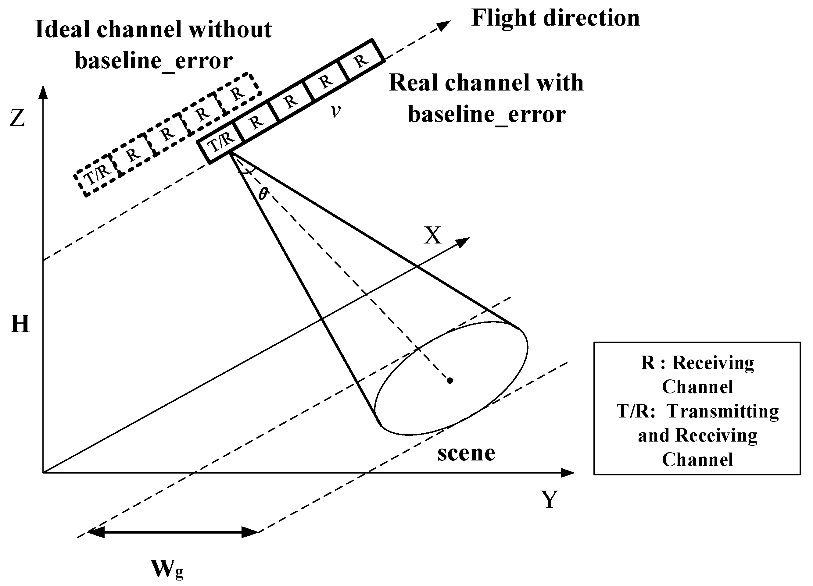
As shown in Figure 1, the azimuth multichannel SAR moves along the X-axis at the velocity , and each channel is distributed along the azimuth direction ( in Figure 1). The channel located at the center of the antenna transmits LFM signal, and all channels can receive radar echo. denotes the shortest slant range from the radar trajectory to the scene, denotes the initial position of the radar on the X axis, represents the azimuth slow time, and represents the range fast time.
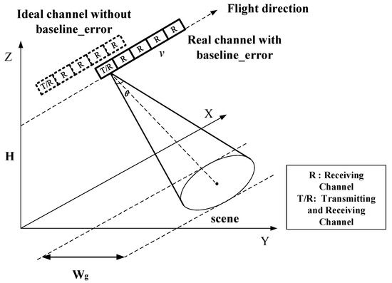
Figure 1.
Azimuth multichannel SAR imaging geometry.
Then, the slant range history expression of the m-th channel () in the radar antenna is as follows:
where is the real baseline position of the m-th channel. is the ideal baseline position of the m-th channel. denotes the baseline error of the m-th channel. Then, the two-dimensional time-domain signal expression of the m-th channel signal can be expressed as:
where x denotes the coordinates of the x-axis when the platform is moving, (m = 1,2…M) is the phase error of the m-th channel relative to the reference one, and are the window functions of the range time domain signal and azimuth time do-main signal, respectively ( and are the frequency domain expressions of the corresponding window functions, respectively). After range pulse compression processing, the signal expression of the two-dimensional frequency domain without azimuth ambiguity is:
where indicates the carrier frequency.
In order to achieve high azimuth resolution and a wide-range observation band, the signal of each channel is under-sampled in azimuth. In the case of azimuth ambiguity, assuming that the azimuth ambiguity number is (where is a non-zero natural number), the expression of the two-dimensional frequency domain of the signal in the m-th channel is:
where represents the ambiguous azimuth spectrum, and its expression is as follows:
When the baseline of the antenna channel is inaccurate, is the true baseline of the m-th channel; thus, when the traditional preprocessing operation is performed to align the multichannel SAR data, the preprocessing function can only be constructed by using the known ideal baseline, which is as follows:
Then, the result of preprocessing with the ideal baseline is the following expression:
In the above formula, the second exponential term represents the preprocessed constant steering vector term, and it is related to the real channel baseline that is unknown. This problem will be analyzed at the end of this section. The third exponential term is the linear phase varying with Doppler frequency due to the antenna baseline error, which makes the multichannel image set unable to be accurately aligned in azimuth time.
After imaging processing of each channel data, the image domain expression is as follows:
where the imaging result of the ambiguity component of the i-th azimuth spectrum in the two-dimensional time domain can be expressed by two-dimensional inverse Fourier transform of , which is the signal in the azimuth frequency domain. is expressed as the following expression:
where:
It can be seen from the expression of the multichannel in the image domain that due to the existence of the antenna baseline error along the azimuth direction, the steering vector of the image domain becomes two parts compared with the constant without-baseline error: one is , which is the constant steering vector related to the real antenna baseline with error, and the other is , the azimuth frequency linear phase related to the antenna baseline error. When the azimuth inter-channel error exists, although the real antenna baseline cannot be obtained before processing, the constant phase term caused by the antenna baseline error does not affect the phase error estimation using the image joint-pixel method.
After preprocessing, the multichannel data has also been coarsely calibrated in the azimuth time domain, and there is only a small time shift caused by the antenna baseline error in the azimuth direction. Fortunately, this time shift is smaller than that caused by different channel receiving positions, and the effect of this small time shift is often less than one pixel. In order to eliminate the influence of the registration error (small time shift) caused by the remaining small linear phase in the frequency domain, the joint-pixel method is used to construct the data vector for spatial estimation in the next section.
To facilitate the subsequent formula derivation and representation, all M channel images can be written in the following vectors:
3. Proposed Method
3.1. Image-Domain Channel Phase Error Estimation Method Based on Single Pixel
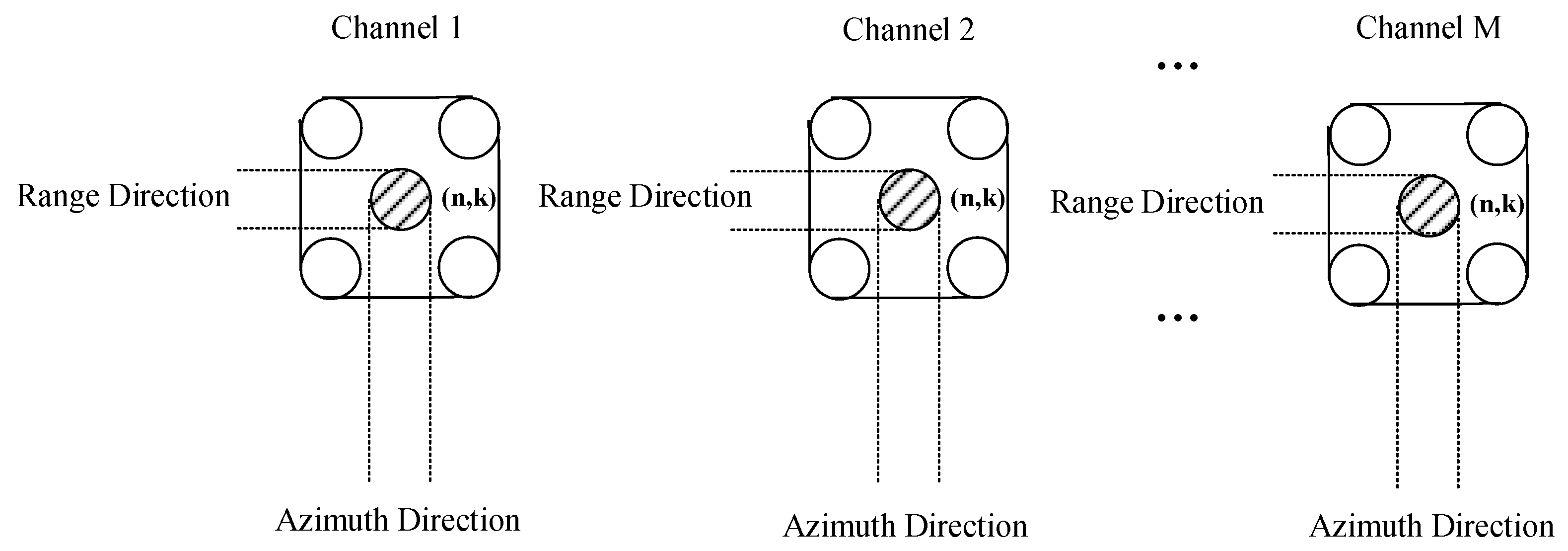
Figure 2 is a schematic diagram of a single-pixel data vector. The multichannel signal in the image domain can be written as the following matrix form:
where:
where denotes the diagonal matrix composed of multichannel phase error terms. is the phase error of the m-th channel relative to the reference channel (where the reference channel is the first one). represents the imaging result, and is the image domain steering vector matrix.
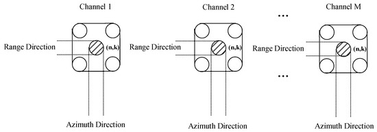
Figure 2.
Schematic diagram of single pixel data vector.
Where and the following equation is satisfied:
according to the principle of statistical expectation, the covariance matrix is calculated by:
Considering the linear independence of the steering vector corresponding to each ambiguity number, the rank of the covariance matrix can be obtained by combining the above formula.
Further, the noise subspace of the image can be obtained by feature decomposition, and the following equation is derived by the orthogonality between the steering vector of the signal and the noise subspace of the image:
where denotes the modulo operator, and is column i of the steering vector matrix , representing the steering vector of the i-th ambiguity component. When the channel error estimation is accurate, based on the orthogonal characteristics of the signal subspace and the noise subspace, will be equal to zero. Therefore, the research on the channel error problem can be transformed into the following expression:
where and is the column vector operator composed of diagonal vectors of the matrix. . Then, the above equation can be solved under the condition of linear constraint (where ), and the optimal solution is:
where:
Therefore, the channel error can be obtained by calculating .
In summary, in the method using a single pixel, the baseline error makes it difficult to accurately register the pixels. In fact, in this case, the method of iteratively estimating the baseline error and phase error is usually used, which increases the amount of calculation. Based on the above analysis, the use of joint pixels can recover the coherent information lost during non-registration, avoid iterations in the algorithm, and improve computational efficiency.
3.2. Image-Domain Channel Phase Error Estimation Method Based on Joint Pixel
According to the derivation in Section 2, the imaging results are obtained. Based on this, the characteristics of the image can be analyzed, and the two-dimensional signal can be expressed as pixels in the distance and azimuth direction. Let and be the discrete sampling point (or pixel) position of range time and azimuth time , respectively. Then, the discrete expression of image of the m-th channel is expressed as .
The basic principle of the joint-pixel method is to select a specific point and several points around it in the image as the data vector that constitutes the joint pixel. When constructing the joint-pixel data vector, the selection of joint pixels and the construction of data vectors in the image is involved. For joint-pixel selection, one should include the method in reference [26] and a single pixel for the reference channel, which is widely used for clutter suppression under the condition that the SAR image or InSAR image is not accurately registered or in the accuracy estimation of the moving target motion parameters in the existing reference [25]. Compared with the traditional method, the particularity of our method is reflected in the selection and construction method of joint pixels. In order to achieve better error estimation performance, it is necessary to fully extract the information of each channel. Therefore, this paper focuses on the method of using the joint pixel for the reference channel.
For the data vector construction method, this paper proposes a method of directly accumulating the joint pixels of each channel to make the data vector dimension consistent with the number of channels and a method of forming the data vector by the joint pixels to make the data vector dimension greater than the number of channels. Based on this, this paper evaluates the channel error estimation performance of the two construction methods in simulation experiments.
As shown in Figure 3, using the pixel at the position of the multichannel SAR image as an example, all channels select a total of pixels in the rectangular area around the pixel (where and are natural numbers and not 0 at the same time).

Figure 3.
Schematic diagram of joint-pixel data.
When the selected pixels are directly used to form a joint-pixel data vector, the data vector expression is as follows:
where:
When the joint pixels of all channels are accumulated in complex form to obtain a pixel value instead of directly forming a data vector, each pixel value retains the information of all pixels’ amplitude and phase superposition. This accumulation method is used due to the fact that when the baseline error exists, the same scattering point is misplaced in the pixel positions of different channels, and the accumulation of joint pixels is essentially a local average, similar to a spatial domain low-pass filter. Since the phase error caused by misalignment is non-correlated between adjacent pixels, the random phase perturbation will be suppressed by offsetting via accumulating the complex pixels in the J × J neighborhood.
At this time, the joint-pixel vector is defined as the following expression:
where:
In the previous section, two definitions of joint-pixel data vectors are compared. Among them, for the case of pixel addition, since the size of the data vector after addition of the joint pixels of each channel is consistent with that when a single pixel performs channel error estimation, the estimation function can be derived by referring to the method of using a single pixel to achieve error estimation. Therefore, this section only derives the image subspace formula of the joint-pixel method for the case of directly constructing vectors with pixels. In the derivation in this section, without loss of generality, channel 1 is used as the reference channel.
The image matrix expression based on the joint pixel can be defined as:
where consists of elements. The multichannel phase error matrix and the steering vector matrix are expressed as:
Similarly, the covariance matrix of the joint-pixel method is expressed as:
By eigenvalue decomposition of the joint-pixel covariance matrix , the estimated image noise subspace can be obtained. According to the orthogonality of the signal and noise subspaces, the following equality can be obtained:
Furthermore, the image subspace channel error estimation based on the joint-pixel method can be equivalent to solving the following problems:
where . . Under the linear constraint condition (, where in the traditional joint-pixel construction method), the above formula can obtain the optimal solution as follows:
where:
Therefore, the estimation value of the channel error can be obtained by . Finally, the estimated channel phase error can be compensated for by the multichannel SAR images to obtain a well-calibrated, ambiguity-free HRWS SAR image after post-imaging reconstruction [26,27,28,29]. Compared with compensating channel phase errors for the raw multichannel SAR data, this operation avoids a redundant SAR imaging processing leading to a calculation amount deduction.
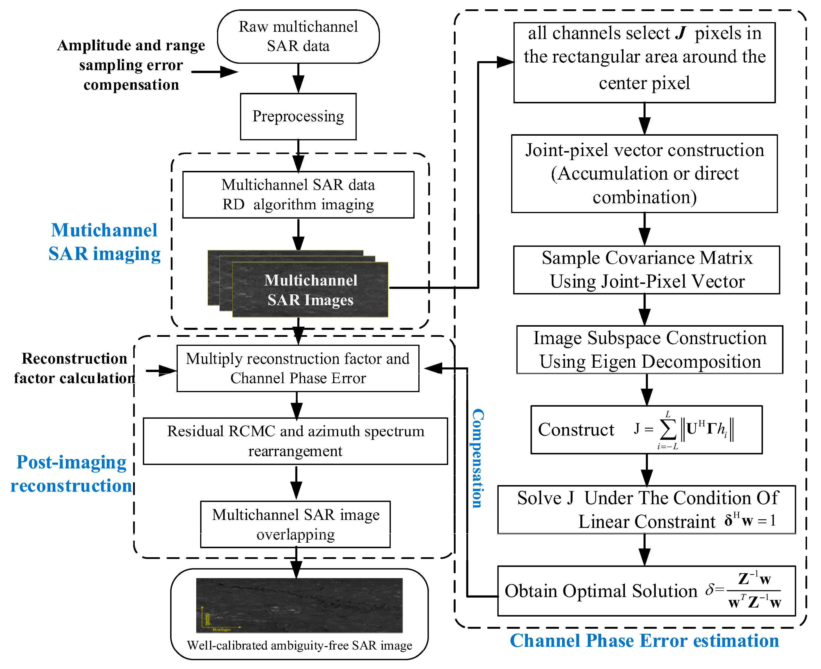
The processing flow of the method is shown in Figure 4, including imaging and joint-pixel selection for each channel, eigenvalue decomposition of the joint-pixel covariance matrix, solution of the optimization equation, and channel error estimation.
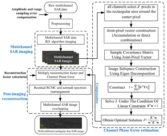
Figure 4.
Processing flows of image-subspace phase error estimation method based on joint pixel.
4. Results
4.1. Simulated Data Experiment
In order to solve the problem that the estimation accuracy of the subspace-based phase error estimation method decreases when the antenna azimuth baseline error exists, an image subspace method based on joint pixels is proposed to improve the channel phase error estimation accuracy in this case. In Section 4, two joint-pixel data vector construction methods are compared, and the estimation performance of them will be analyzed experimentally.
According to the discussion in Section 2, due to the existence of baseline error, the correlation between the signal components corresponding to the ambiguity number is destroyed, and the spatial dimension of the covariance matrix is increased; that is, the rank of the covariance matrix is increased, and the subspace is expanded. Therefore, the noise subspace of the image obtained by feature decomposition is inaccurate, which leads to the loss of error estimation accuracy. In order to compensate for the coherent information of the non-registered part lost in this case, the surrounding pixels are jointly processed to recover the coherent information of the elements as much as possible.
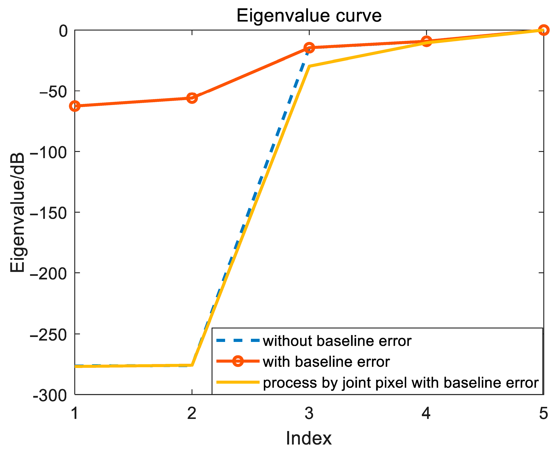
Figure 5 shows the change in the normalized characteristic spectrum of the covariance matrix R calculated by the simulation data (channel number is 5, ambiguity number is 3). When there is no baseline error, three large eigenvalues can be obtained. When the baseline error exists, the rank of the covariance matrix increases, and the eigenvalue structure changes. By selecting and constructing the joint-pixel vector, the eigenvalue structure is corrected, which weakens the influence of image mismatch caused by baseline error.
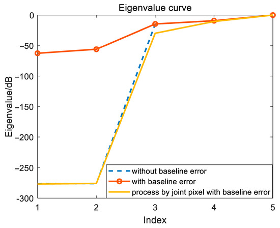
Figure 5.
Normalized characteristic spectrum of the covariance matrix R.
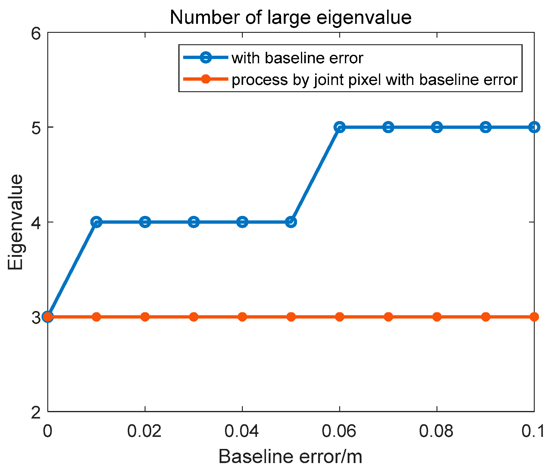
Further quantitative analysis of the influence of baseline error on the change trend of the number of large eigenvalues is shown in Figure 6. As the baseline error gradually increases to 0.1 m, the number of large eigenvalues in the covariance matrix obtained by joint-pixel estimation is basically stable, while the number of large eigenvalues gradually increases to 5 when the single-pixel method is used.
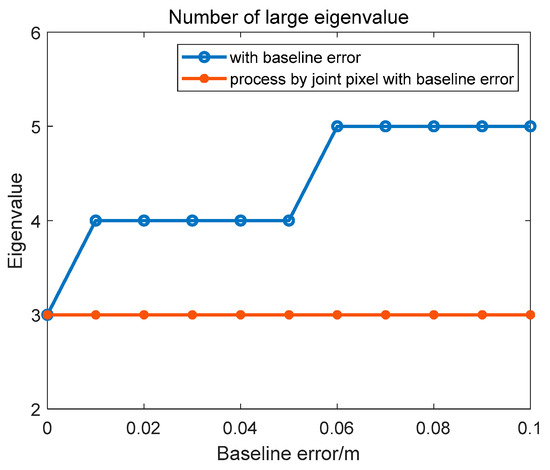
Figure 6.
Large eigenvalue of the covariance matrix change curve.
In this section, the echo data is the simulated five-channel with three-azimuth ambiguity spaceborne SAR data obtained by extracting the three high-resolution single-channel strip data. The system parameters of the simulation experiment are shown in Table 1, where the transmitted signal is in the C-band. The five antenna channels are distributed along the direction of radar motion, in which the channel at the center position transmits LFM signal, and all channels are used as receiving channels. The Doppler bandwidth of the echo calculated according to the size of the transmitting antenna is approximately 2580 Hz; according to the PRF of 860 Hz, the ambiguity number can be approximately 3.

Table 1.
Simulation system parameters.
In this simulation experiment, the original phase error of the channel and the antenna azimuth baseline error are set to be constant errors, as shown in Table 2. In the experiment, the channel phase error and the antenna azimuth baseline error shown in Table 2 are used for simulation.

Table 2.
Phase and baseline error in multichannel SAR data generated by simulation experiments.
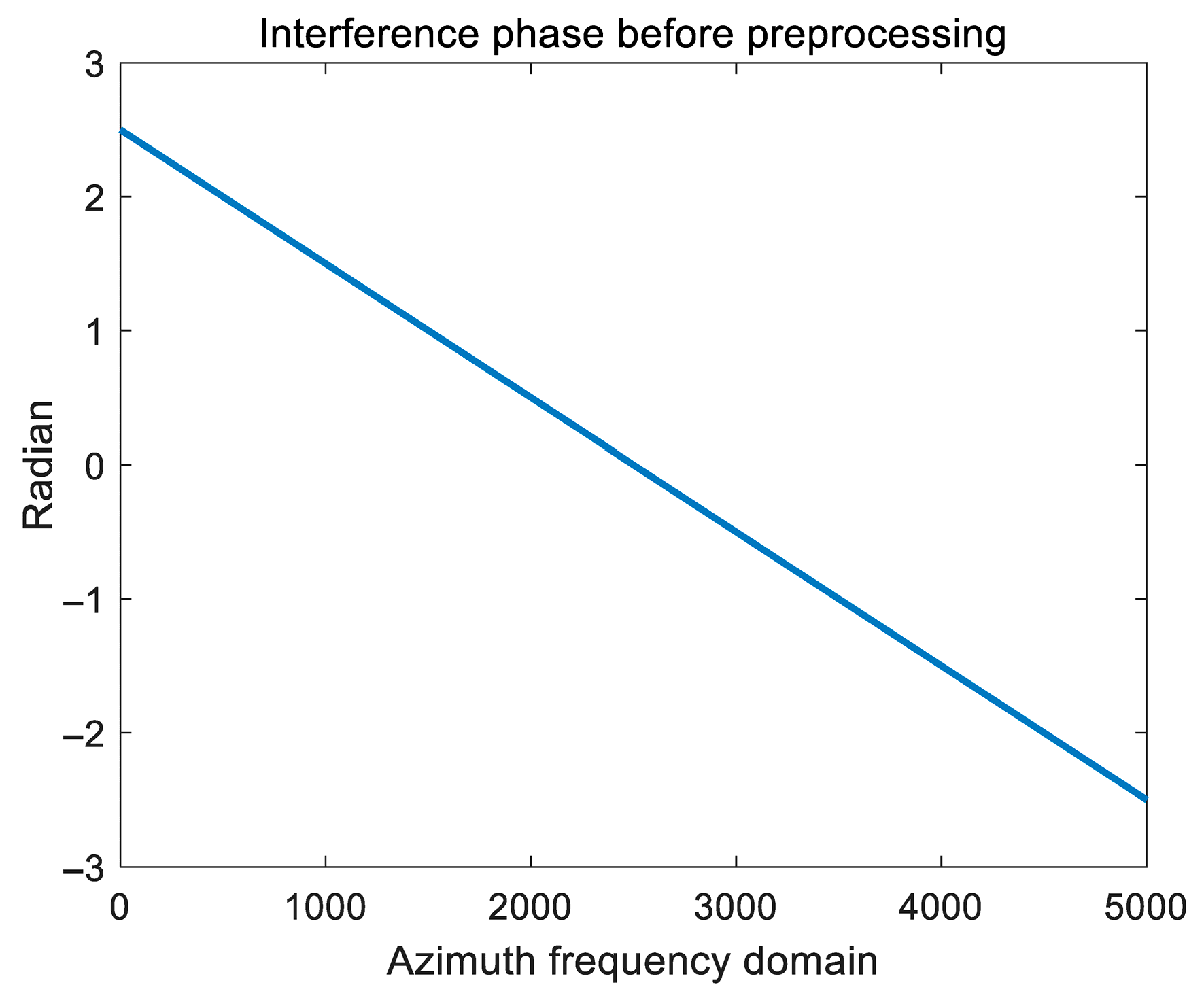
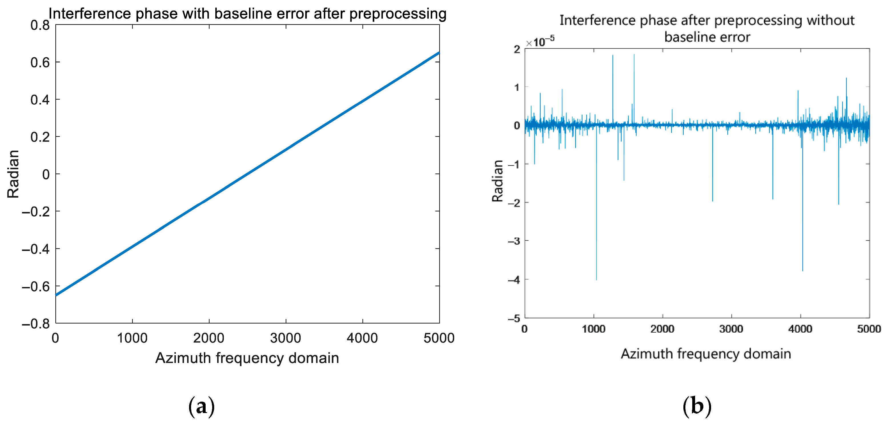
Figure 7 shows the interference phase in the azimuth frequency domain before the preprocessing operation. The phase caused by the antenna azimuth baseline is linear in the azimuth frequency domain. Figure 8a shows the channel interference phase after preprocessing with azimuth baseline error. Figure 8b shows the channel interference phase after preprocessing when there is no azimuth baseline error (the processing result fluctuates around 0, indicating that the linear phase brought upon by the antenna azimuth baseline is accurately calibrated), indicating that there is a calibration error after image preprocessing when there is azimuth baseline error.
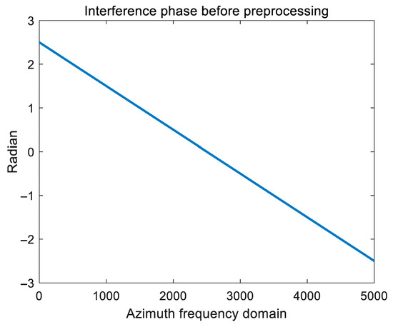
Figure 7.
Interference phase before preprocessing.
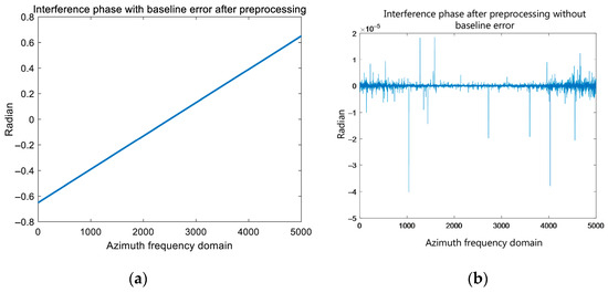
Figure 8.
Phase diagram after preprocessing. (a) With baseline error. (b) Without baseline error.
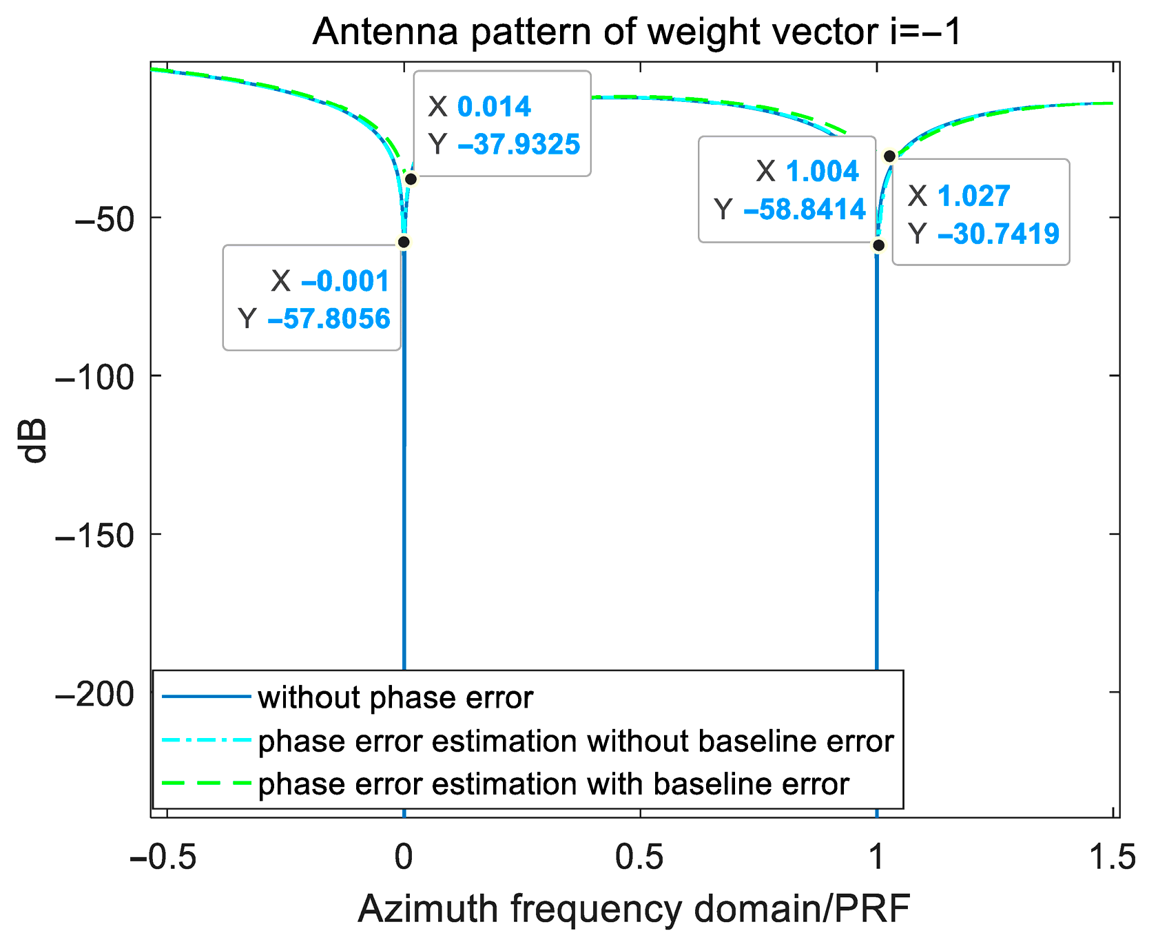
Figure 9 shows the antenna pattern of different ambiguity components obtained by estimating and compensating the phase error with or without baseline error and compares them with the case without phase error, using the extraction of ambiguity component −1 as an example. It can be seen intuitively from the figure that when there is a baseline error, the accuracy of phase error estimation will be affected.
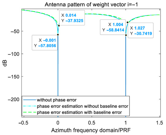
Figure 9.
Antenna pattern of different ambiguity components.
The variation in the channel phase error estimation accuracy of the two joint-pixel data vector construction methods introduced in the previous section with the SNR is simulated and analyzed. Among them, the channel phase error estimation accuracy is evaluated as the root mean square error (RMSE) of the error estimate and the true value. The root mean square error is defined as follows:
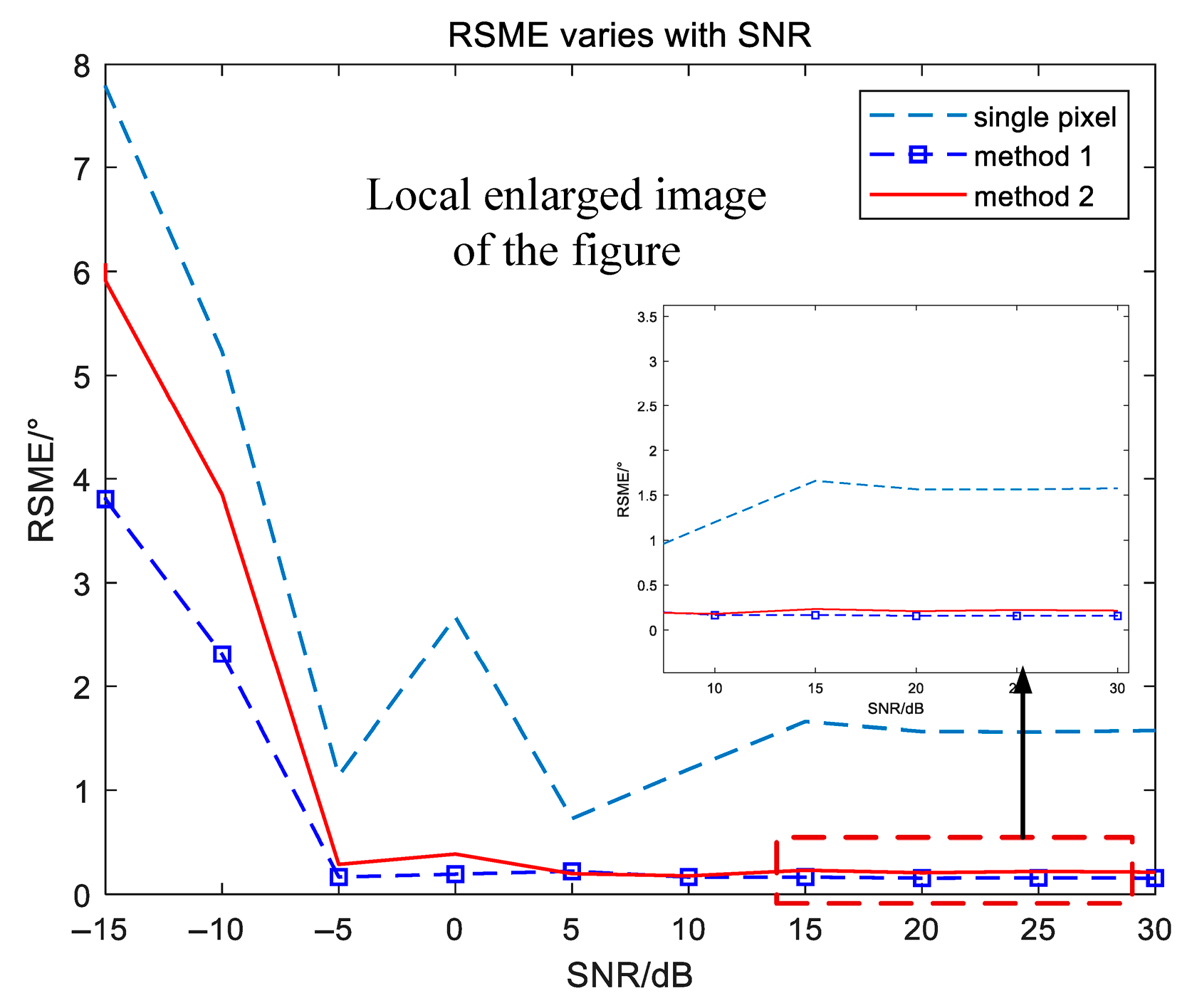
In the simulation analysis, when the baseline error of the azimuth antenna exists, the inter-channel noise is assumed to be Gaussian white noise. In the experiment, a noise signal with SNR of −10 dB to 30 dB is added to the echo data, and the area selected by the joint pixel is set to a square area with a side length of 3 pixels. Figure 10 shows the RSME of the channel phase error estimation results corresponding to two proposed joint-pixel data vector construction methods and the traditional single-pixel image subspace method [29], which is used to analyze the influence of the above methods on the phase error estimation accuracy under different SNRs. The sub-window is the local enlarged image of Figure 10.
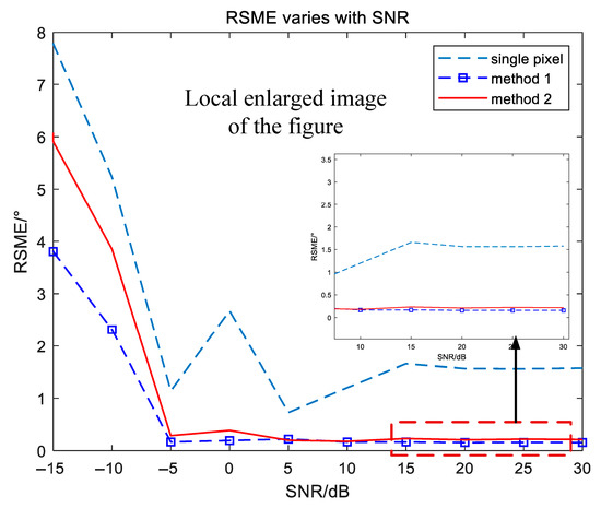
Figure 10.
Channel error estimation accuracy and its local magnification.
It can be seen from Figure 10 that the two proposed methods are superior to the single-pixel method. After the image SNR reaches 5 dB, the RSMEs of the two joint-pixel construction methods gradually stabilize and remain near 0.15 dB and 0.22 dB, respectively. When the SNR is greater than 15 dB, the single-pixel method gradually stabilizes at 1.45 dB as the SNR increases. Therefore, when there is an error in the antenna azimuth baseline, the two joint-pixel vector construction methods can greatly improve the accuracy of channel error estimation, and when the number of selected joint pixels is small, the accuracy difference between the two is not significant.
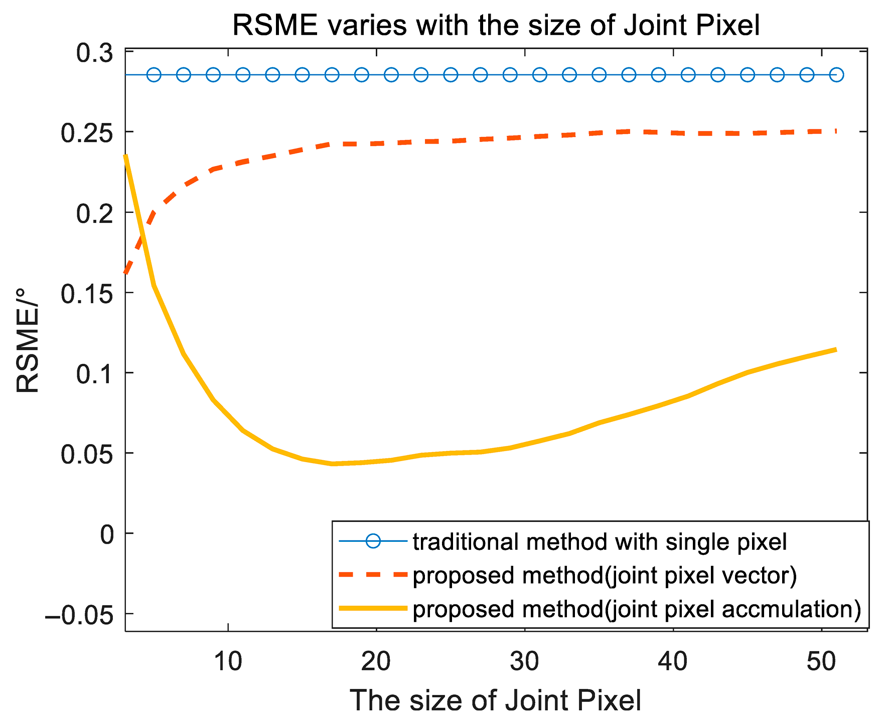
In addition, it is also necessary to evaluate the influence of the number of pixels on the RSME of the error estimation in the two joint-pixel data vector construction methods. Under the condition that SNR is set to 15 dB, the curve of RSME with the number of joint-pixel vectors is shown in Figure 11, where the size of the joint-pixel vector in the abscissa refers to the size of the square side length pixel in the joint-pixel selection area. It can be seen from Figure 11 that with the increase in the number of joint pixels, the performance of the two methods with joint pixel shows different changes. Among them, the joint-pixel vector method does not change significantly with the increase in the number of joint pixels, and its RSME remains near 0.25 degrees. The improvement of the accumulating method is obvious with the increase in the number of joint pixels. When the side length of the joint-pixel region is greater than 5 pixels, the channel error estimation accuracy of joint-pixel accumulation method is better than that of constructing a joint-pixel vector.
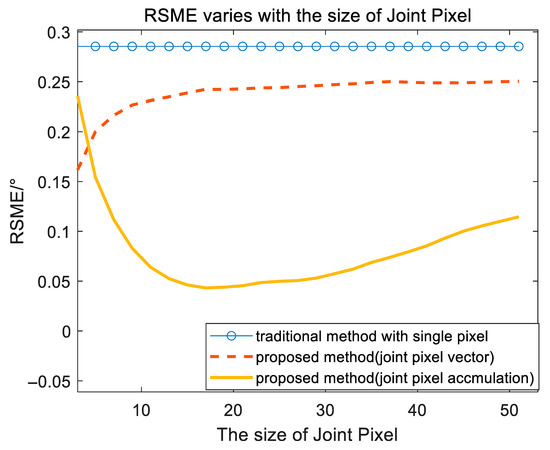
Figure 11.
The RSME of phase error estimation of different construction methods varies with the joint-pixel size.
After further simulation verification, the RSME of the proposed method by joint-pixel accumulation can reach 0.11 degrees when the side length of the joint pixel is 9 pixels; Table 3 shows the error estimation results and running time when the side length of the joint pixel is 9 pixels.

Table 3.
Channel phase error estimation results of different joint-pixel data vector construction methods.
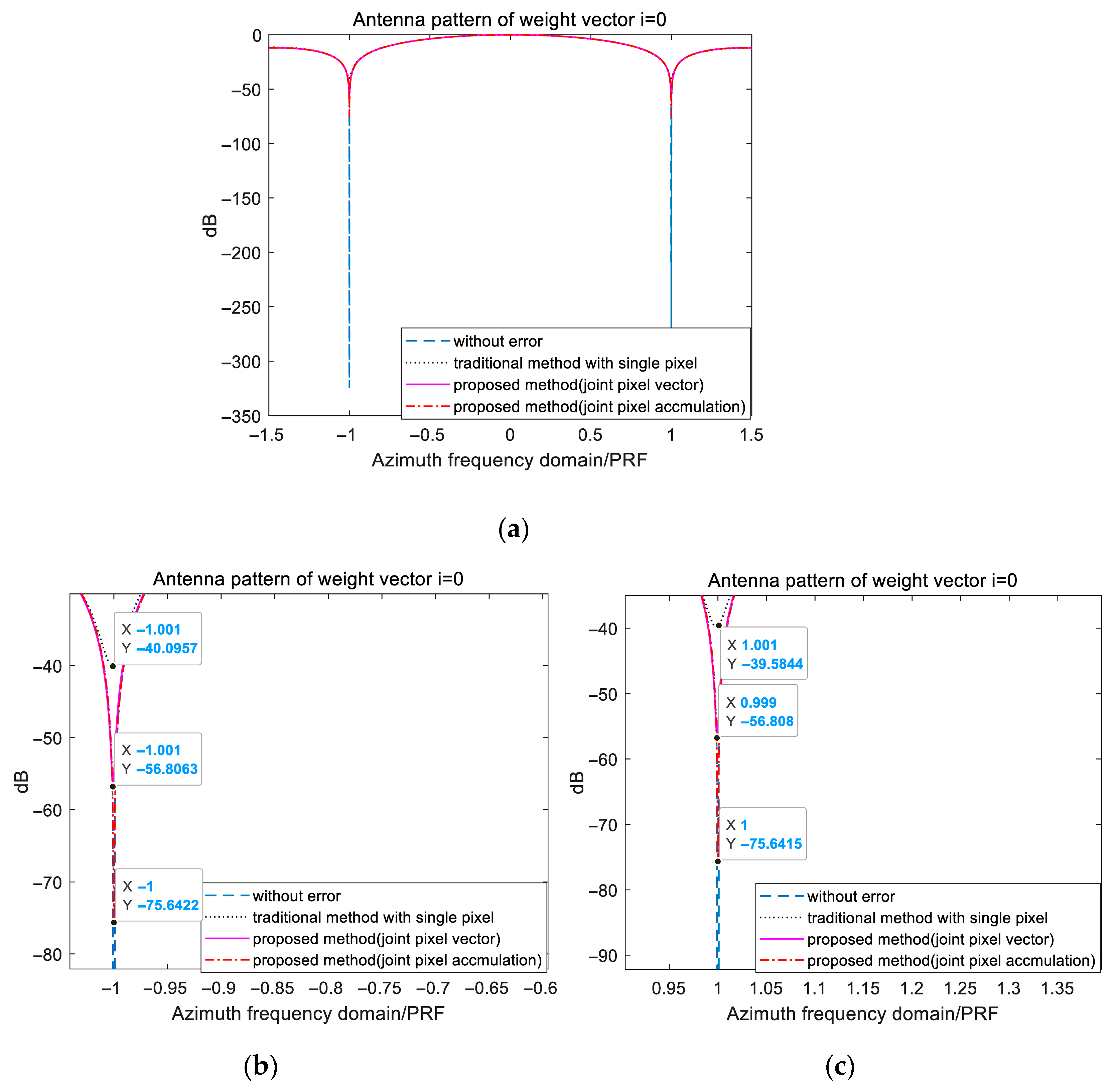
In order to further compare the influence of phase estimation accuracy on multichannel signal reconstruction, using the extraction of ambiguity component 0 as an example, Figure 12 shows the influence of phase error compensation by different joint-pixel construction methods on the antenna pattern (zero Doppler bin) of different ambiguity components. Between the traditional method and proposed method, the groove formed by joint-pixel accumulation at the position of the ambiguity component is the deepest, and the depth is about −10 dB deeper than that of constructing a joint-pixel vector. In some SAR images with high SNR or sea scenes, the estimation accuracy of joint-pixel accumulation will produce a better suppression effect on ambiguity.
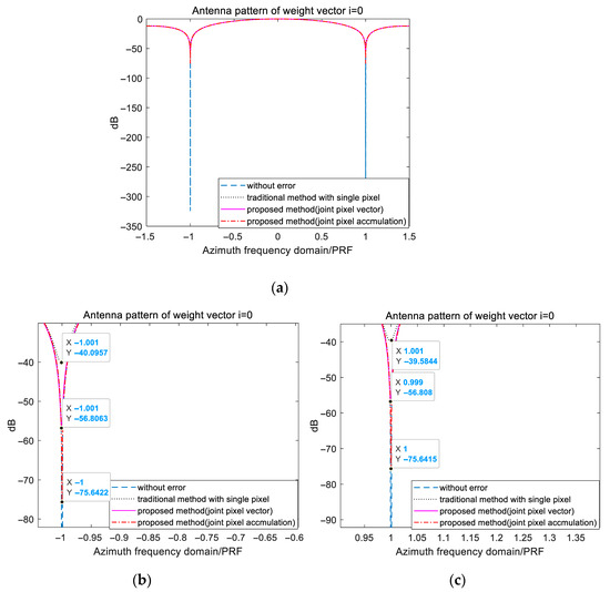
Figure 12.
Zero Doppler position to extract the pattern of baseband ambiguity component (weight vector i = 0). The original diagram (a) and local enlarged diagram (b,c).
The estimation results of the proposed method based on joint-pixel accumulation in the case of a joint-pixel area side length of 51 pixels are used to compensate and reconstruct the multichannel data to obtain the final unambiguous SAR image. The following are some imaging results:
Figure 13a,b shows the reconstructed SAR images before and after the channel phase error compensation estimated by the proposed method. It can be seen from the figure that the azimuth ambiguity is effectively suppressed, which verifies the effectiveness of the proposed method.

Figure 13.
Simulation imaging results. Multichannel reconstructed SAR image with uncompensated channel error (a) and multichannel reconstructed SAR image after channel phase error compensation (b).
4.2. Analysis of the Computational Complexity
On the basis of verifying the performance of the proposed method, one can analyze the computational complexity of the traditional method and the proposed one for error estimation based on joint pixels. In the process of constructing joint pixels and estimating phase errors, the calculation amount is mainly concentrated on covariance estimation, eigenvalue decomposition, and optimal weight calculation. Therefore, in this paper, the calculation amount of the two methods in these three steps is mainly counted, and the results are shown in Table 4.

Table 4.
The main time consumption of the two methods.
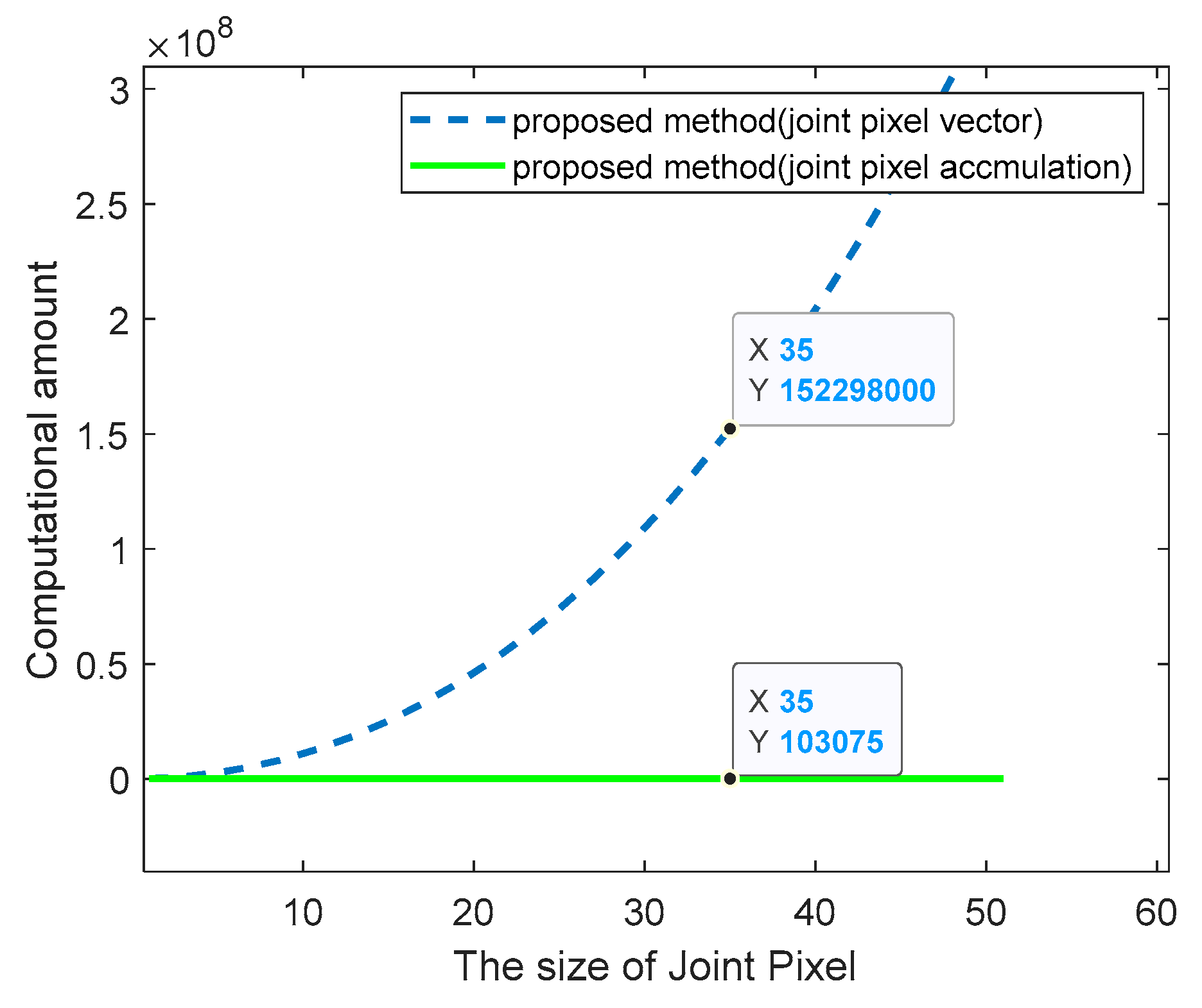
From Table 4, it can be concluded that the main computational complexity of the joint-pixel vector constructing method is related to the product of the number of channels and the number of selected joint pixels, while the main computational amount of the proposed method based on joint-pixel accumulation is only related to the number of channels. According to the theoretical values of the calculation amount of the two methods, the computational amount curve with the change in the number of joint pixels is as follows in Figure 14.
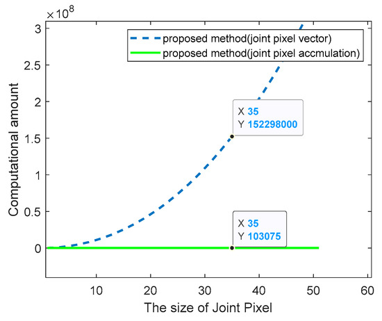
Figure 14.
The computational complexity varies with the size of joint pixel.
4.3. Acquired SAR Data Processing
The previous simulation experiments have proved the effectiveness of the proposed method. The following tests the effect of the method based on joint-pixel accumulation in processing the airborne multichannel SAR data, which is collected by an azimuth seven-channel SAR system. The system parameters in this mode are shown in Table 5: the platform speed is 110 m/s, PRF = 200 Hz, the transmitted signal is C-band. One channel transmits a chirp signal, and the seven channels are all receiving channels to receive echoes. The ambiguity number of the azimuth Doppler bandwidth calculated according to the size of the transmitting antenna is approximately 5.

Table 5.
The parameters of airborne 7-channel SAR.
In fact, the phase error for the real data is a random value caused by the channel and the environment. In the actual measurement, the true value of the phase error cannot be directly obtained. In the experiment, we use the proposed method to estimate the error and then evaluate the clarity of the image. Compared with the traditional method and the results before error correction, the evaluation results of the proposed method are obtained.
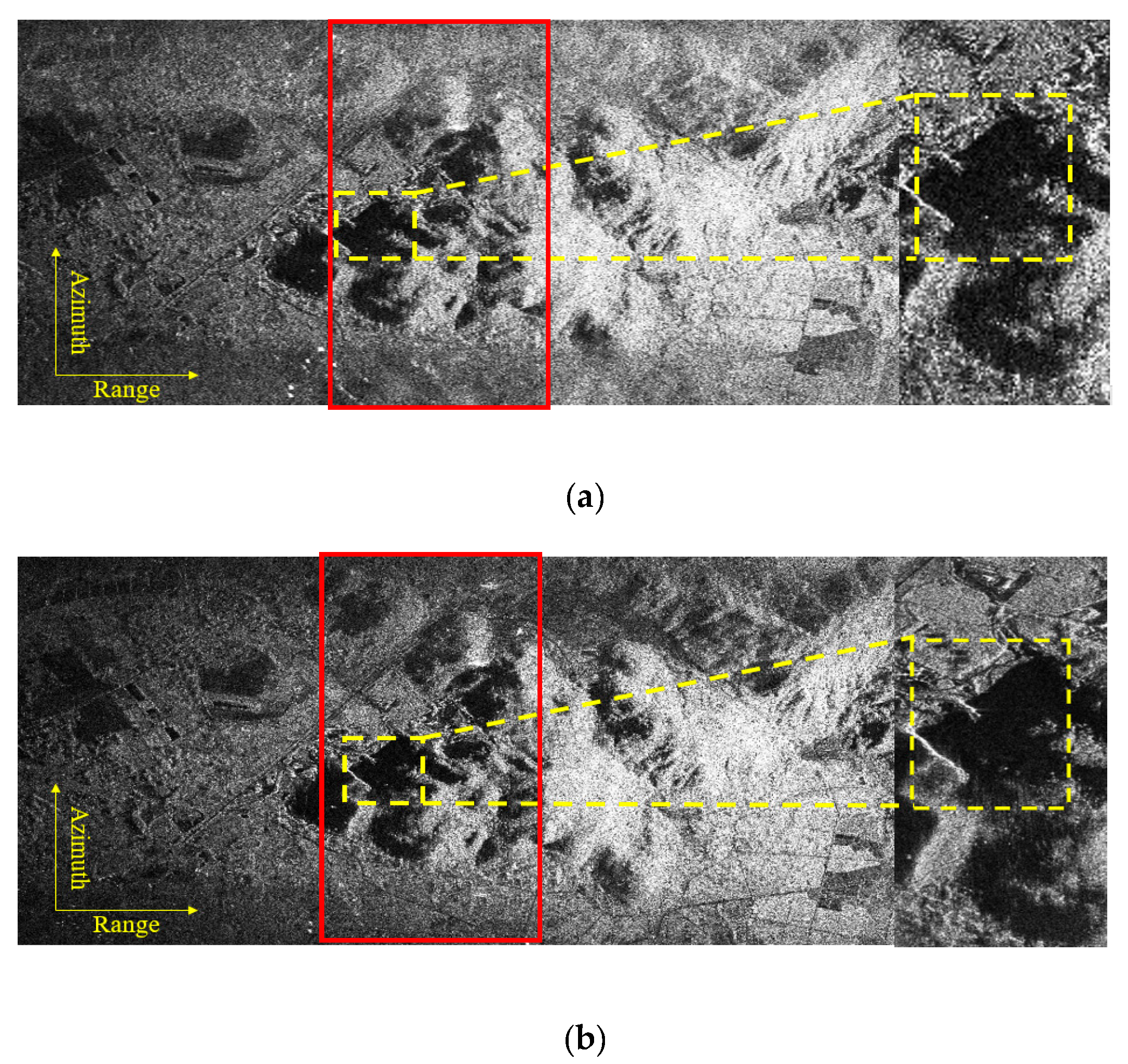
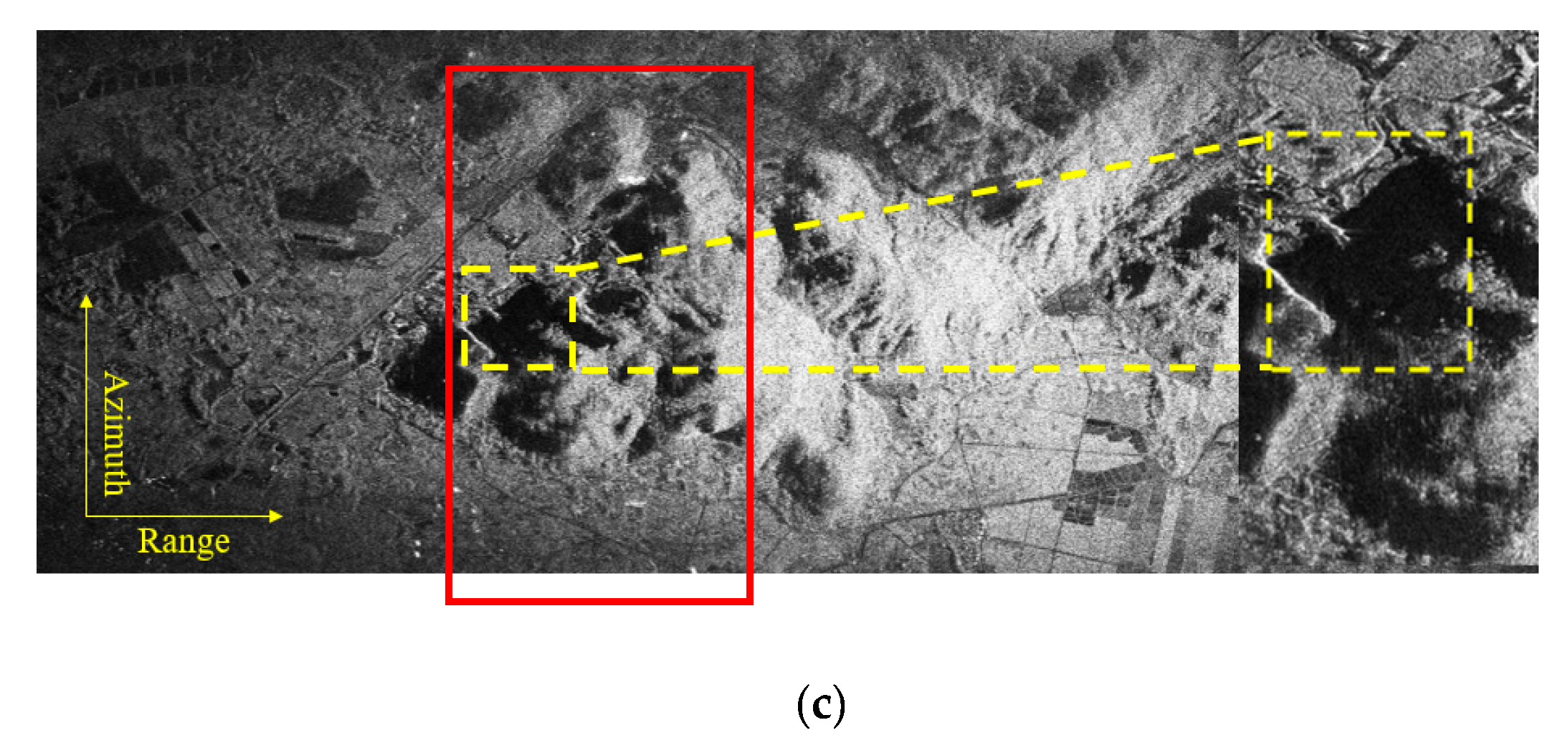
The following diagrams shows the results without the error compensation (shown in Figure 15a), after error compensation using the traditional single-pixel method (shown in Figure 15b), and using the proposed method (in Figure 15c). Among them, the compared single-pixel method also transforms the signal into the image domain and then estimates the covariance matrix and performs eigenvalue decomposition. Then, the orthogonal relationship between the two subspaces of image domain signal and noise is used to solve the optimization problem and estimate the channel error.
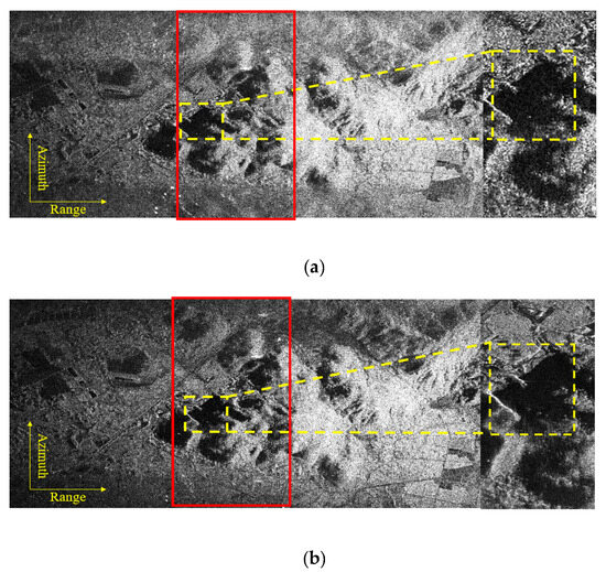
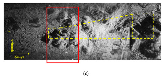
Figure 15.
Imaging results of airborne acquired SAR data. Imaging results without error compensation (a), after error compensation by traditional method with single pixel (b), and after error compensation with joint pixel (c). (The selected part of the red box is enlarged, and the shadow part is in the yellow box).
It can be seen from Figure 15 that the proposed method can effectively suppress ambiguity and reduce ghosting compared with the case without error correction, and a well-focused image with clearer details is obtained.
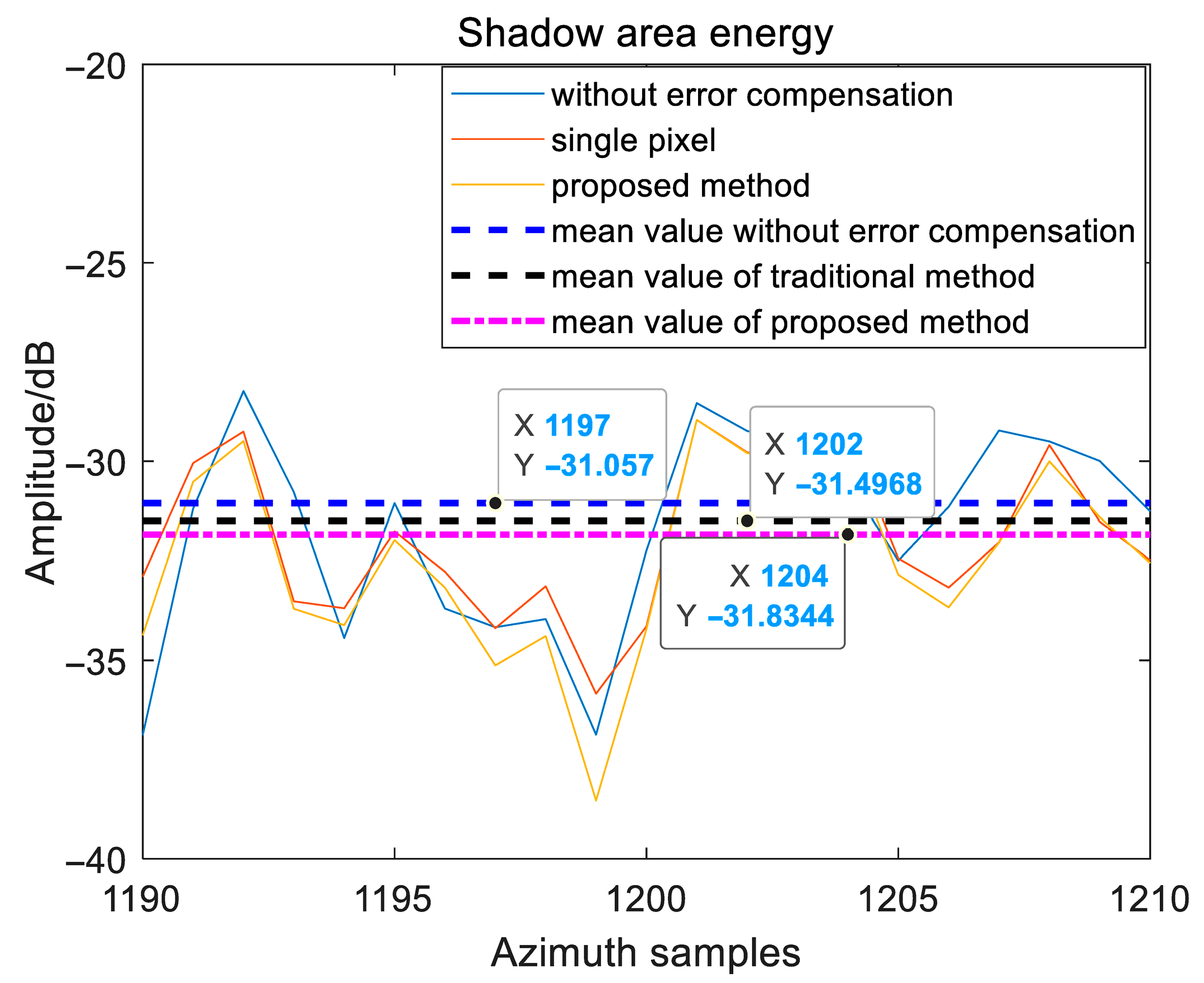
In order to further compare the performance difference between the proposed method and the single-pixel method, the shadow area energy comparison of the resulting images processed by the two methods is provided as a way to quantify the effect of our method. The shadow area is extracted as shown in Figure 15. The energy of the shadow area after the phase error is processed by the traditional method, and the proposed method is calculated; the results are 603.62 and 569.58, respectively. In addition, the part of the shadow area processed by the above two methods is used to count the energy in the azimuth direction, and the result is shown in Figure 16. It can be seen from the figure that the energy of the shadow area is lower than that of the traditional method after using the proposed method to estimate and compensate for the phase error. That is, after the proposed method is processed, the ability to suppress the ambiguity energy is enhanced, which verifies the effectiveness of the proposed method.
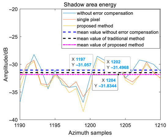
Figure 16.
Azimuth energy analysis of the shadow area.
5. Discussion
This paper proposes a method for estimating the phase error between multichannels in the image domain based on joint pixel. This method can achieve high precision and efficiency imaging under the presence of baseline errors. Combined with simulation experiments, the number of selected pixels and the impact of constructing data vectors on computational efficiency is considered.
For high-precision imaging, the impact of baseline errors cannot be ignored. The existence of baseline error will lead to the mismatch of multichannel images, which is reflected in the increase in the rank of the covariance matrix and the change in the eigenvalue structure. For the simulation data (channel number is 5, ambiguity number is 3) in this paper, in the ideal state, the number of large eigenvalues should be 3, but from Figure 5 and Figure 6, it can be observed that the number of large eigenvalues will increase with an increase in baseline error, which will affect the optimization problem in error estimation. However, after the processing of the joint-pixel method proposed in this paper, the number of eigenvalues can be maintained at 3, which is consistent with the ideal state.
When using the joint-pixel method proposed in this paper for error estimation, the number of joint pixels selected needs to be considered. It can be seen from Figure 11 that with an increase in the number of pixels, the proposed method using joint-pixel accumulation can achieve higher phase error estimation accuracy with less time consumed than another joint-pixel construction method. When the side length is greater than 20 pixels, the accuracy of the proposed method by joint-pixel accumulation will decrease. This is because the required coherent information will not spread to a larger range. When the selected joint pixel exceeds a certain threshold, additional redundant information will be introduced, and accuracy will be lost. Therefore, during application, the number of joint pixels should be selected according to the actual situation (e.g., considering the SNR and other parameters), and the number of joint pixels should not be too large, which will lead to a decrease in operation efficiency and the interference of fuzzy signals.
In addition, the specific operational efficiency comparison also needs to be considered. For the two joint-pixel data construction methods proposed in this paper, it can be seen from Figure 14 that as the number of joint pixels increases, the computational complexity of the method that constructs a joint-pixel vector increases rapidly (up to thousands of times more than that of the joint-pixel accumulation), which verifies the theoretical time consumption of the two methods obtained by statistics in Table 4.
In practical applications, distance sampling delay error and orbit error can be equivalent to channel phase error. In this case, the method proposed in this paper has application value, as it effectively corrects the error, meets the needs of multichannel SAR high-precision imaging, and suppresses the misjudgment caused by baseline deviation in the detection scene.
6. Conclusions
In order to solve the problem that the accuracy of channel phase error estimation decreases when the antenna azimuth baseline is inaccurate in a multichannel SAR system, a high-precision phase error estimation method based on image-domain joint-pixel accumulation is proposed. Firstly, the working principle and signal model of multichannel SAR are introduced. Then, the proposed joint-pixel data vector construction methods for channel phase error estimation are analyzed. At the end of this paper, the influence of two methods on the accuracy of channel phase error estimation is evaluated by simulation experiments, and the effectiveness of the proposed method based on joint-pixel accumulation is verified by the acquired data. It is determined that the proposed method can achieve superior performance under the condition of joint pixels.
Author Contributions
Conceptualization, J.F., J.X. and G.S.; methodology, X.D.; software, J.X. and X.D.; validation, Q.C., X.D. and W.Z.; formal analysis, J.F.; writing—original draft preparation, X.D. and W.Z.; writing—review and editing, J.X. and W.Z.; supervision, J.F. and G.S.; funding acquisition, J.X. and G.S. All authors have read and agreed to the published version of the manuscript.
Funding
This work was supported by the National Natural Science Foundation of China under Grant 62401442 and 62222113.
Data Availability Statement
The data that support the findings of this study are available from the corresponding author upon reasonable request.
Acknowledgments
We are very grateful to all reviewers, institutions, and studies for their help and advice on our work.
Conflicts of Interest
The authors declare no conflicts of interest.
References
- Sun, G.-C.; Liu, Y.; Xiang, J.; Liu, W.; Xing, M.; Chen, J. Spaceborne Synthetic Aperture Radar Imaging Algorithms: An overview. IEEE Geosci. Remote Sens. Mag. 2022, 10, 161–184. [Google Scholar] [CrossRef]
- Wang, Y.; Sun, G.-C.; Xiang, J.; Xing, M.; Guo, L.; Yang, J. A Imaging Passive Localization Method for Wideband Signal Based on SAR. In Proceedings of the 2019 6th Asia-Pacific Conference on Synthetic Aperture Radar (APSAR), Xiamen, China, 26–29 November 2019. [Google Scholar]
- Ji, Y.; Dong, Z.; Zhang, Y.; Wang, C.; Hu, C.; Xu, Z. Trans-ionospheric Synthetic Aperture Radar Observation: A Comprehensive Review. IEEE Geosci. Remote Sens. Mag. 2025, 13, 273–313. [Google Scholar] [CrossRef]
- Ji, Y.; Dong, Z.; Zhang, Y.; Tang, F.; Mao, W.; Zhao, H.; Xu, Z.; Zhang, Q.; Zhao, B.; Gao, H. Equatorial Ionospheric Scintillation Measurement in Advanced Land Observing Satellite (ALOS) Phased Array-Type L-Band Synthetic Aperture Radar (PALSAR) Observations. Engineering 2025, 47, 70–85. [Google Scholar] [CrossRef]
- Curlander, J.; Mcdonough, R. Synthetic Aperature Radar: Systems and Signal Processing; Wiley: New York, NY, USA, 1991; pp. 205–215. [Google Scholar]
- Yang, W.; Li, C.; Chen, J.; Wang, P.B. Effects of time synchronization on image quality of spaceborne multi-channels SAR. Chin. J. Radio Sci. 2011, 26, 636–640. [Google Scholar]
- Xu, W.; Huang, P.; Wang, R.; Deng, Y. Processing of Multichannel Sliding Spotlight and TOPS Synthetic Aperture Radar Data. IEEE Trans. Geosci. Remote Sens. 2013, 51, 4417–4429. [Google Scholar] [CrossRef]
- Chen, Q.; Deng, Y.; Wang, R.; Liu, Y. Investigation of Multichannel Sliding Spotlight SAR for Ultrahigh-Resolution and Wide-Swath Imaging. IEEE Geosci. Remote Sens. Lett. 2013, 10, 1339–1343. [Google Scholar] [CrossRef]
- Qian, J.; Sun, G.-C.; Li, L.; Xing, M. Multichannel SAR high speed target indication with improved detection probability. Chin. J. Radio Sci. 2011, 26, 354–361. [Google Scholar]
- Liu, Y.; Wang, H.; Liao, G. Calibration and remedy for multichannel imaging satellites. Chin. J. Radio Sci. 2005, 20, 614–618. [Google Scholar]
- Li, X.; Xing, M.; Xia, X.-G.; Sun, G.-C.; Liang, Y.; Bao, Z. Deramp Space–Time Adaptive Processing for Multichannel SAR Systems. IEEE Geosci. Remote Sens. Lett. 2014, 11, 1448–1452. [Google Scholar]
- Zhou, Y.; Wang, W.; Chen, Z.; Zhao, Q.; Zhang, H.; Deng, Y.; Wang, R. High-Resolution and Wide-Swath SAR Imaging Mode Using Frequency Diverse Planar Array. IEEE Geosci. Remote Sens. Lett. 2021, 18, 321–325. [Google Scholar] [CrossRef]
- Zhou, Y.; Wang, W.; Chen, Z.; Wang, P.; Zhang, H.; Qiu, J. Digital Beamforming Synthetic Aperture Radar (DBSAR): Experiments and Performance Analysis in Support of 16-Channel Airborne X-Band SAR Data. IEEE Trans. Geosci. Remote Sens. 2021, 59, 6784–6798. [Google Scholar] [CrossRef]
- Ender, J.; Berens, P.; Brenner, A.R.; Rossing, L.; Skupin, U. Multichannel SAR/MTI system development at FGAN: From AER to PAMIR. In Proceedings of the IEEE International Geoscience and Remote Sensing Symposium, Toronto, ON, Canada, 24–28 June 2002; Volume 3, pp. 1697–1701. [Google Scholar]
- Baumgartner, S.; Gabele, M.; Gebert, N.; Scheiber, R.; Krieger, G.; Bethke, K.-H.; Moreira, A. Digital beamforming and traffic monitoring using the new FSAR system of DLR. In Proceedings of the International Radar Symposium (IRS), Cologne, Germany, 5–7 September 2007. [Google Scholar]
- Liu, A.; Wang, F.; Xu, H. Nriet-SAR: A new Multichannel Multi-Mode Polarimetric Airborne SAR. IEEE J. Sel. Top. Appl. Earth Obs. Remote Sens. 2017, 8, 3155–3166. [Google Scholar]
- Morena, L.; James, K.; Beck, J. An introduction to the RADARSAT-2 mission. Can. J. Remote Sens. 2004, 30, 221–234. [Google Scholar] [CrossRef]
- Kankaku, Y.; Suzuki, S.; Osawa, Y. ALOS-2 mission and development status. In Proceedings of the 2013 IEEE International Geoscience and Remote Sensing Symposium—IGARSS, Melbourne, VIC, Australia, 21–26 July 2013; pp. 2396–2399. [Google Scholar]
- Lehner, S.; Schulz-Stellenfleth, J.; Brusch, S.; Li, X.M. Use of TerraSAR-X data for oceanography. In Proceedings of the 7th European Conference on Synthetic Aperture Radar, Friedrichshafen, Germany, 2–5 June 2008. [Google Scholar]
- Zhang, Q. System Design and Key Technologies of the GF-3 Satellite. Acta Geod. Cartogr. Sin. 2017, 46, 269–277. [Google Scholar]
- Zhang, S.-X.; Li, S.; Liu, Y.; Xing, M.-D.; Chen, J. A Novel Azimuth Doppler Signal Reconstruction Approach for the GEO-LEO Bi-Static Multichannel HRWS SAR System. IEEE Access 2019, 7, 39539–39546. [Google Scholar] [CrossRef]
- Mapelli, D.; Guccione, P.; Giudici, D.; Stasi, M.; Imbembo, E. Generalization of the Synthetic Aperture Radar Azimuth Multi-Aperture Processing Scheme—MAPS. Remote Sens. 2024, 16, 3170. [Google Scholar] [CrossRef]
- Kim, J.-H.; Younis, M.; Prats-Iraola, P.; Gabele, M.; Krieger, G. First spaceborne demonstration of digital beamforming for azimuth ambiguity suppression. IEEE Trans. Geosci. Remote Sens. 2013, 51, 579–590. [Google Scholar] [CrossRef]
- Younis, M.; Fischer, C.; Wiesbeck, W. Digital beamforming in SAR systems. Remote Sens. 2003, 41, 1735–1739. [Google Scholar] [CrossRef]
- Sun, G.-C.; Xiang, J.; Wang, Y.; Zhang, Z.; Yang, J.; Xing, M. A Postmatched-Filtering Image-Domain Subspace Method for Channel Mismatch Estimation of Multiple Azimuth Channels SAR. IEEE Trans. Geosci. Remote Sens. 2022, 60, 5100614. [Google Scholar] [CrossRef]
- Xu, Y.; Zhang, F.; Chen, L.; Wan, Y.; Jiang, T. A Novel Error Correction Method for Airborne HRWS SAR Based on Azimuth-Variant Attitude and Range-Variant Doppler Domain Pattern. Remote Sens. 2025, 17, 2831. [Google Scholar] [CrossRef]
- Xiang, J.; Ding, X.; Sun, G.-C.; Zhang, Z.; Xing, M.; Liu, W. An Efficient Multichannel SAR Channel Phase Error Calibration Method Based on Fine-Focused HRWS SAR Image Entropy. IEEE J. Sel. Top. Appl. Earth Obs. Remote Sens. 2022, 15, 7873–7885. [Google Scholar] [CrossRef]
- Hu, J.; Wang, Y.; Xie, J.; Fang, G.; Chen, H.; Shen, Y.; Yang, Z.; Zhang, X. Channel Amplitude and Phase Error Estimation of Fully Polarimetric Airborne SAR with 0.1 m Resolution. Remote Sens. 2025, 17, 2699. [Google Scholar] [CrossRef]
- Li, Z.; Bao, Z.; Wang, H.; Liao, G. Performance improvement for constellation SAR using signal processing techniques. IEEE Trans. Aerosp. Electron. Syst. 2006, 42, 436–452. [Google Scholar] [CrossRef]
- Ma, L.; Liao, G.; Li, Z. An Approach for Multichannel SAR Array Error Compensation and Its Verification by Measured Data. J. Electron. Inf. Technol. 2009, 31, 1305–1309. [Google Scholar]
- Xiang, J.; Sun, G.-C.; Zhang, Z.; Zhang, Y.; Ding, X.; Xing, M. A Robust Image-Domain Subspace-Based Channel Error Calibration and Post imaging Reconstruction Algorithm for Multiple Azimuth Channels SAR. IEEE Trans. Geosci. Remote Sens. 2022, 60, 5215818. [Google Scholar] [CrossRef]
- Li, X.; Xing, M.; Xia, X.-G.; Sun, G.-C.; Liang, Y.; Bao, Z. Simultaneous Stationary Scene Imaging and Ground Moving Target Indication for High-Resolution Wide-Swath SAR System. IEEE Trans. Geosci. Remote Sens. 2016, 54, 4224–4239. [Google Scholar] [CrossRef]
- Wang, Z.; Wang, Y.; Xing, M.; Sun, G.-C.; Zhang, S.; Xiang, J. A Novel Two-Step Scheme Based on Joint GO-DPCA and Local STAP in Image Domain for Multichannel SAR-GMTI. IEEE J. Sel. Top. Appl. Earth Obs. Remote Sens. 2021, 14, 8259–8272. [Google Scholar] [CrossRef]
- Li, Z.; Bao, Z.; Wang, T. Ground Moving Target Indication for Distributed Small Satellite SAR Systems. Acta Electron. Sin. 2005, 33, 1664–1666. [Google Scholar]
- Li, Z.; Bao, Z.; Suo, Z. A Joint Image Coregistration, Phase Noise Suppression, and Phase Unwrapping Method Based on Subspace Projection for Multibaseline InSAR Systems. IEEE Trans. Geosci. Remote Sens. 2007, 45, 584–591. [Google Scholar] [CrossRef]
- Suo, Z.; Li, Z.; Bao, Z. Multichannel SAR-GMTI Method Robust to Coregistration Error of SAR Images. IEEE Trans. Aerosp. Electron. Syst. 2010, 46, 2035–2043. [Google Scholar] [CrossRef]
- Liu, K.; He, X.; Liao, G.; Yu, Y.; Wang, Q. A Robust Multichannel Moving Target Detection Algorithm for Complex Scenes. J. Electron. Inf. Technol. 2024, 46, 2018–2027. [Google Scholar]
Disclaimer/Publisher’s Note: The statements, opinions and data contained in all publications are solely those of the individual author(s) and contributor(s) and not of MDPI and/or the editor(s). MDPI and/or the editor(s) disclaim responsibility for any injury to people or property resulting from any ideas, methods, instructions or products referred to in the content. |
© 2025 by the authors. Licensee MDPI, Basel, Switzerland. This article is an open access article distributed under the terms and conditions of the Creative Commons Attribution (CC BY) license (https://creativecommons.org/licenses/by/4.0/).

