Abstract
Bistatic active sonar enables robust and precise target position and tracking, making it a key technology for autonomous underwater vehicles (AUVs) in underwater surveillance. This paper proposes a multi-information-assisted target tracking algorithm for bistatic active sonar, leveraging spatial and temporal echo signal structures to address the challenges of AUVs in shallow water. First, broadened cluster formations in sonar echoes are analyzed, leading to the integration of a spatial clustering-based data association. This paper departs from conventional methods by fusing target position, echo amplitude, and Doppler information during the movement of AUVs, which can improve the efficiency of association probability computation. The re-derived multi-information-assisted association probability calculation method and algorithmic workflow are explicitly designed for real-time implementation in AUV systems. Simulation experiments verify the feasibility of integrating Doppler and amplitude information. The sea trial data from simulated AUV-deployed bistatic sonar contained only amplitude information due to experimental limitations. By utilizing this amplitude information, the algorithm proposed in this paper demonstrates a 23.95% performance improvement over the traditional probabilistic data association algorithm. The proposed algorithm provides AUVs with enhanced tracking autonomy, significantly advancing their capability in ocean engineering applications.
1. Introduction
Compared to monostatic active sonar, bistatic active sonar with separate transmission and reception equipment positioned at different locations offers higher survivability and detection capabilities [1,2], particularly when deployed on coordinated autonomous underwater vehicles (AUVs) for distributed surveillance [3,4]. This architecture attracts wide attention due to its potential in AUV-enabled persistent target tracking, especially in anti-submarine warfare and marine monitoring [5,6]. By leveraging AUVs as mobile bistatic nodes, the spatially separated transmitter and receiver can dynamically cover expansive areas through path planning, overcoming the spatial constraints of static sonar arrays in complex environments [7]. AUVs can actively adjust transmitter–receiver geometries to evade counter-detection. These advantages make bistatic active sonar in AUVs highly valuable in marine monitoring applications.
To obtain target tracking states, traditional bistatic sonars employ a one-way information transmission framework of detection followed by tracking [8,9,10]. However, due to the complex time-varying and spatially varying nature of the underwater acoustic channel, the results of active sonar target detection are influenced by noise, multipath, Doppler frequency, and reverberation, which are prone to errors, false alarms, and errors [11,12,13]. In addition, active sonar operates at low frequencies with limited bandwidth and small array apertures, leading to significant measurement errors. Moreover, the relatively slow speed of sound in water results in long detection times to cover a certain area, leading to low data rates [14]. Consequently, active sonar target tracking faces challenges such as low detection probability, high clutter rates, low data rates, and large measurement errors. During the target tracking process, sonars can obtain various target feature information such as amplitude, echo width, and Doppler [15,16]. If these pieces of information can be fed back and used properly, the detection and tracking performance of targets is expected to be improved.
When a target is identified on the bearing–time figure during active detection, many measurements can be obtained. Traditional active sonar target tracking algorithms typically use the point with the highest amplitude from the acquired measurements for state filtering, without utilizing the remaining measurements. These measurements are generated due to various factors, such as sidelobes of echoes and multipath arrivals, reflecting spatial and temporal broadening [17]. Thus, we can obtain spatial clustering results of echo signals. Scholars have proposed data association techniques to handle many measurements, aiming to establish the association between each measurement and the true target, which is helpful for using the acquired measurements [18,19]. Building upon this, many scholars have conducted extensive research on utilizing target feature information for tracking and have proposed improvement algorithms for data association algorithms. Although target feature information cannot be used directly to update tracks, it can effectively reduce the uncertainty in track association and play a significant role in association probability calculations. Furthermore, combining the auxiliary target information can expand the dimension of the measurement information and help identify and remove clutter [20].
Some scholars have proposed methods based on sound speed profile models to compensate for tracking errors caused by the bending of acoustic propagation paths. However, these approaches require substantial computational resources and prior knowledge [21]. In active sonar, amplitude and Doppler are two important signal parameters that play a key role in target detection. When a sonar emits sound waves and receives the echoes reflected by the target, if the target is moving relative to the sonar, the frequency of the echo will shift due to the Doppler effect. Amplitude information refers to the amplitude of echo signals after matched filtering in active sonar, typically reflecting the amount of energy in the reflected echo of the target. Using this commonly used information, we can obtain better results. Compared to random finite set (RFS) methods, data association algorithms hold greater advantages in active sonar target tracking due to their refined clutter suppression capabilities and engineering interpretability. In contrast, RFS methods are more suitable for passive sonar scenarios involving dense target environments or highly dynamic target populations [22,23]. Therefore, this paper will utilize the amplitude and Doppler information integrated with data association algorithms for investigation.
The amplitude information was first pointed out in the tracking by the scholar Bar-Shalom Y in 1990 [24]. Then, scholars combined the amplitude information with single-target probabilistic data association (PDA) algorithms and applied them in interactive multiple model (IMM) algorithms, demonstrating the effectiveness of this algorithm [25]. Researchers typically use amplitude information to determine the presence of valid measurements, which is particularly useful in uncertain measurement sources. The amplitude information is independent of position information and can distinguish between measurements originating from target echoes and false alarms. Based on this, it can be used as a weight coefficient for the spatial clustering results of the echo signals from active detection. Introducing amplitude information into the association probability favors measurements with higher amplitudes, thereby influencing the mutual probability. The higher the amplitude of the measurements within the tracking gate, the higher the probability of correctness they are considered to have.
In 2009, the Doppler component was first incorporated into the data association process by Wang X and Musicki D, and its excellent association performance was evaluated. Subsequently, they utilized Doppler information to enhance target state estimation performance and proved the reliability of tracking trajectories under severe clutter interference. Finally, combining these two aspects aimed to improve association efficiency and improve estimation accuracy [26,27]. Different moving targets possess varying Doppler information, enabling multi-target tracking based on Doppler information [28]. In the spatial clustering results of active detection echo signals, Doppler information can be regarded as quantities with minimal variation. Measurements with small Doppler changes in adjacent snapshots are closer to the true target position. Some scholars have modeled the position measurement, radial velocity measurement, and amplitude measurement of active sonar echo signals, calculating the generalized likelihood of measurements and achieving multi-dimensional information fusion. Through Kullback–Leibler divergence, they evaluated the contribution of information fusion, concluding that position, radial velocity, and amplitude information can enhance target tracking [29].
Building upon the aforementioned research, this paper extends the target measurement state by introducing amplitude and Doppler information into the active sonar tracking process without altering the motion equation of the target. Instead of using a single position information measurement likelihood function, this paper proposes a multi-information-assisted PDA tracking algorithm using a joint measurement likelihood function of amplitude, Doppler, and position information. The algorithm first computes the probability weighting coefficient for each valid observation point within the gating region. Then, it associates the amplitude and Doppler information of each echo measurement using an assisted algorithm for data association, thus calculating the weighted sum of all valid observations as the estimated value of true observations. Considering the maneuverability of the targets and AUVs during tracking, the algorithm is combined with an IMM algorithm, introducing a data association algorithm based on multiple models. During the tracking process, the filter system determines the appropriateness of the current model based on the specific probability of each model. Finally, a simulated AUV-deployed bistatic active sonar experiment was conducted in the South China Sea, and the results showed that the proposed algorithm can improve tracking accuracy.
The remainder of this paper is organized as follows: Section 2 details the problems encountered in the positioning and tracking of bistatic active detection. In Section 3, the algorithm proposed in this paper is introduced. Section 4 compares and analyzes the improved algorithm with other algorithms through simulation experiments, validating the effectiveness of the proposed algorithm. The performance of the proposed algorithm is demonstrated using sea trial data. The discussions are shown in Section 5, and the conclusions are provided in Section 6.
2. Related Work
This section introduces the basic principles of bistatic active detection in AUVs, including echo detection algorithms and target location procedures. Subsequently, using an echo data sample from an experiment, the spatial and temporal structure of active detection echoes is presented, which forms the basis for the processing algorithms discussed in this paper.
2.1. Bistatic Active Sonar Detection, Positioning, and Tracking
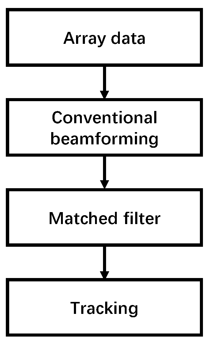
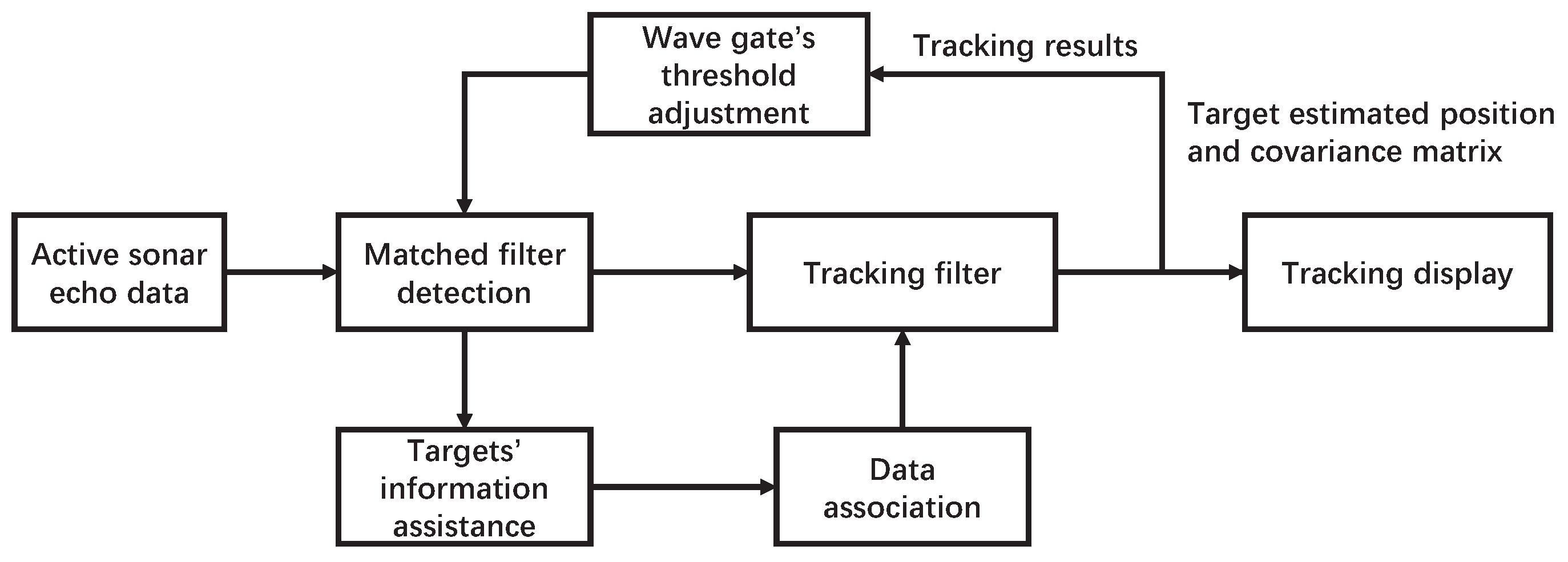
Figure 1 depicts the flow chart of the active sonar signal processing chain, and the bearing–time figure of the conventional beamforming and matched filter is shown in Figure 2. In the active detection system, the source transmits sonar pulses with a given pulse repetition interval. For each ping, the hydrophones of the receiving array collect the acoustic signals in various directions and form beams to obtain the bearing–time figure of the surveillance area. The wider bandwidth of transmitted signals corresponds to higher distance resolution, and more classification features are contained in the signal.

Figure 1.
Active sonar detection and tracking flowchart.
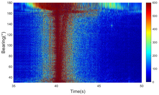
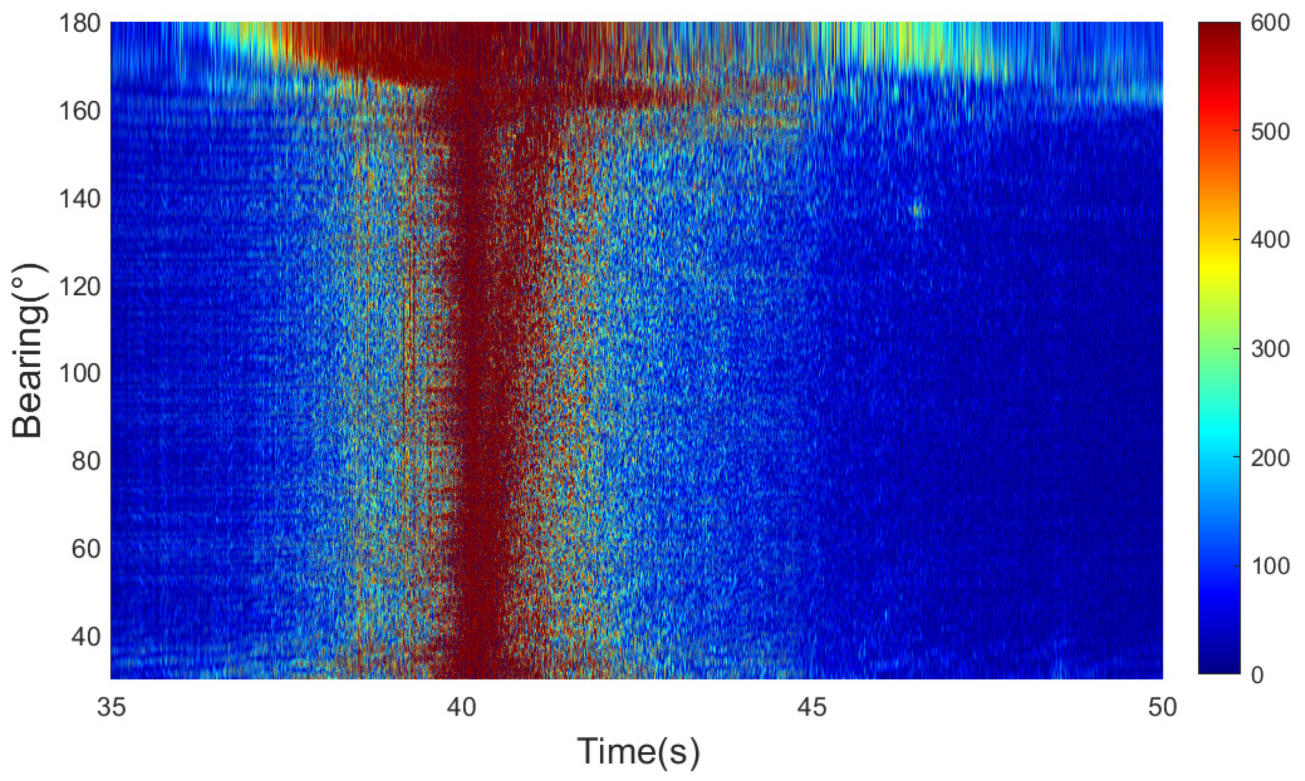
Figure 2.
Active sonar detection result.
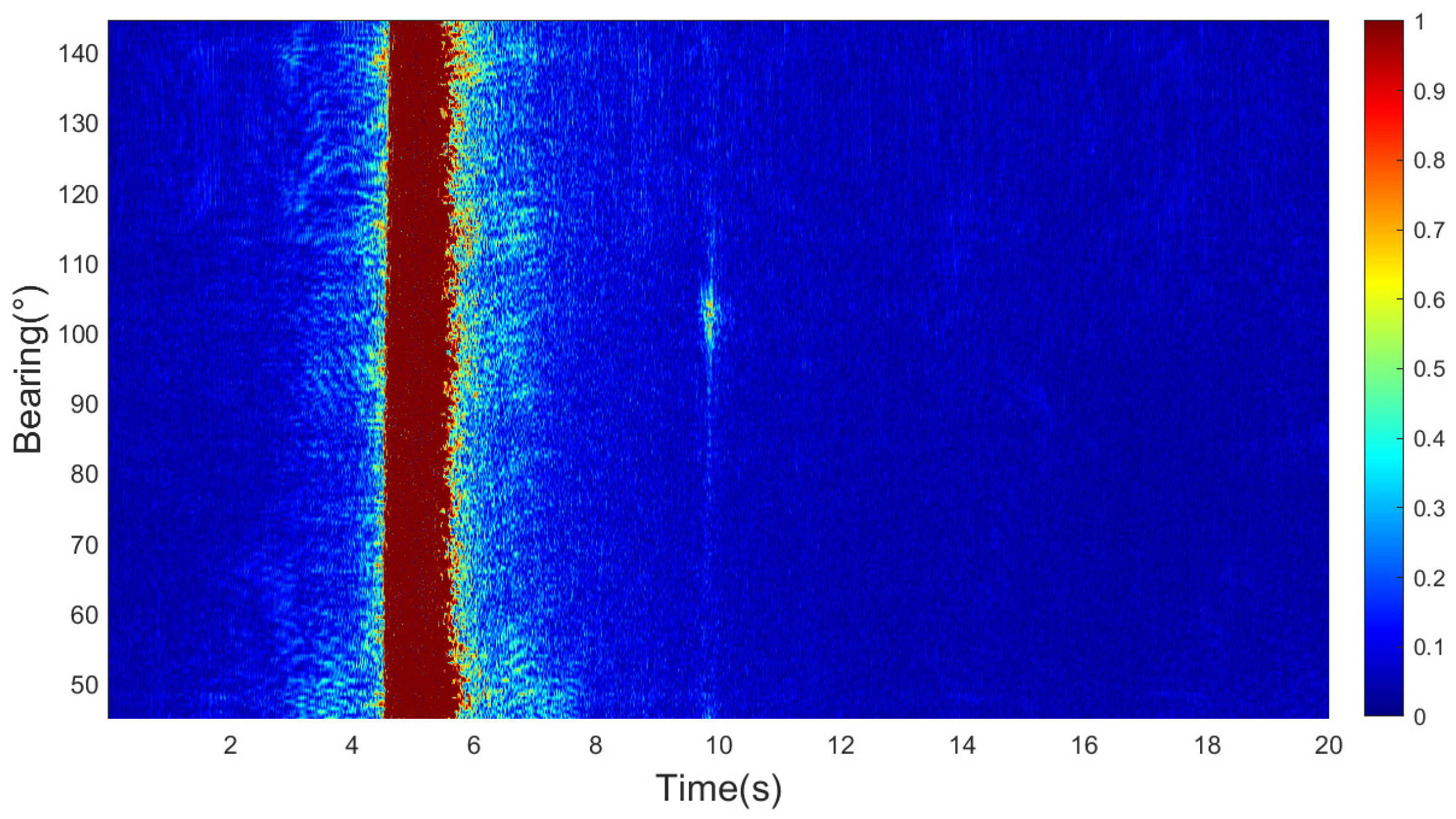
From Figure 2, it can be clearly seen that the first signal that appears is the direct wave with a very high intensity, caused by the high-intensity signal from the sound source reaching the receiver directly. During the beamforming process, the intensity of the direct wave from directions other than the source has been suppressed effectively, allowing the target signal to become more distinct. Further analysis of Figure 2 allows for the determination of the specific bearing and arrival time of the target, which are 136° and 46.37 s. These results serve as input for the subsequent processing in the active sonar, which is the tracking algorithm proposed in this paper.
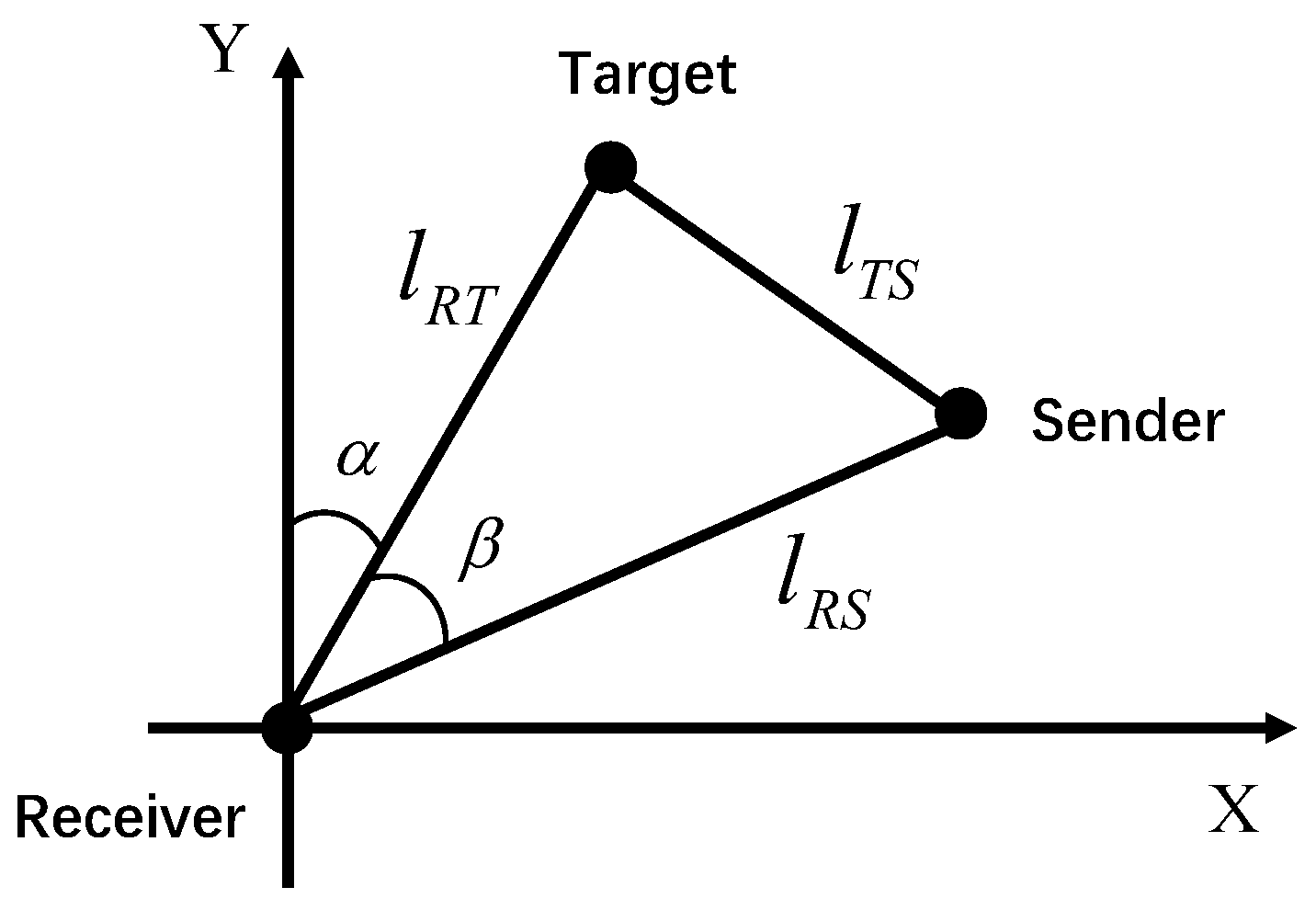
The characteristics of bistatic sonar arise from the separation of transmitter and receiver equipment in different locations; we usually consider the bistatic sonar and the targets in the same plane. Bistatic active sonar is composed of spatially separated sources and receiving arrays, and requires determining target localization based on the geometric relationship among them. Figure 3 illustrates the geometric relationship of the bistatic active detection system, with the receiving array as the origin. represents the distance from the sender to the target, represents the distance from the target to the receiver, represents the distance from the sender to the receiver, denotes the bearing of the target echo, and is the angle between the target–receiver–source. In fact, we can obtain the arrival times of the direct wave and the echo. By calculating the time between these two times and the positions of the transmitter and receiver, we can estimate the position of the target. The specific implementation method is as follows, the time between the direct wave and the echo, named is:
where represents the time from the sender to the target and then to the receiver, and represents the time from the sender to the receiver. Then, we can get:
where c is the sound speed. According to the cosine theorem:

Figure 3.
Positions of the target, sender, and receiver in a bistatic active sonar system.
Substituting Equations (1) and (2) into Equation (3), we can obtain the following:
where the angle is obtained through the bearing of the echo and the bearing of the sound source. The coordinates of the target position are:
where and represents the coordinates of the receiver. The absolute error of the target localization is defined as:
where and are the true coordinates of the target, which can be obtained through satellite positioning. In active sonar, observation measurements will lead to errors, which can cause significant errors in target localization. The main factors contributing to these errors are bearing error, sound speed error, and time error. Sound speed error is primarily caused by the discrepancy between the group velocity of the compressed pulse peak and the reference sound speed [30]. In deep-sea environments, the group velocity distribution varies significantly due to factors such as ocean depth and temperature distribution. Time measurement errors are mainly caused by the precision of pulse signal delay measurement, system delays, and timing synchronization errors of the detection platform. The precision of bearing measurement is primarily determined by the aperture of the array, the correlation radius of the sound field, and the reference phase velocity, which can maintain directional error within 1∼3°.
2.2. Spatial and Temporal Expansion Characteristics of Active Sonar Echoes
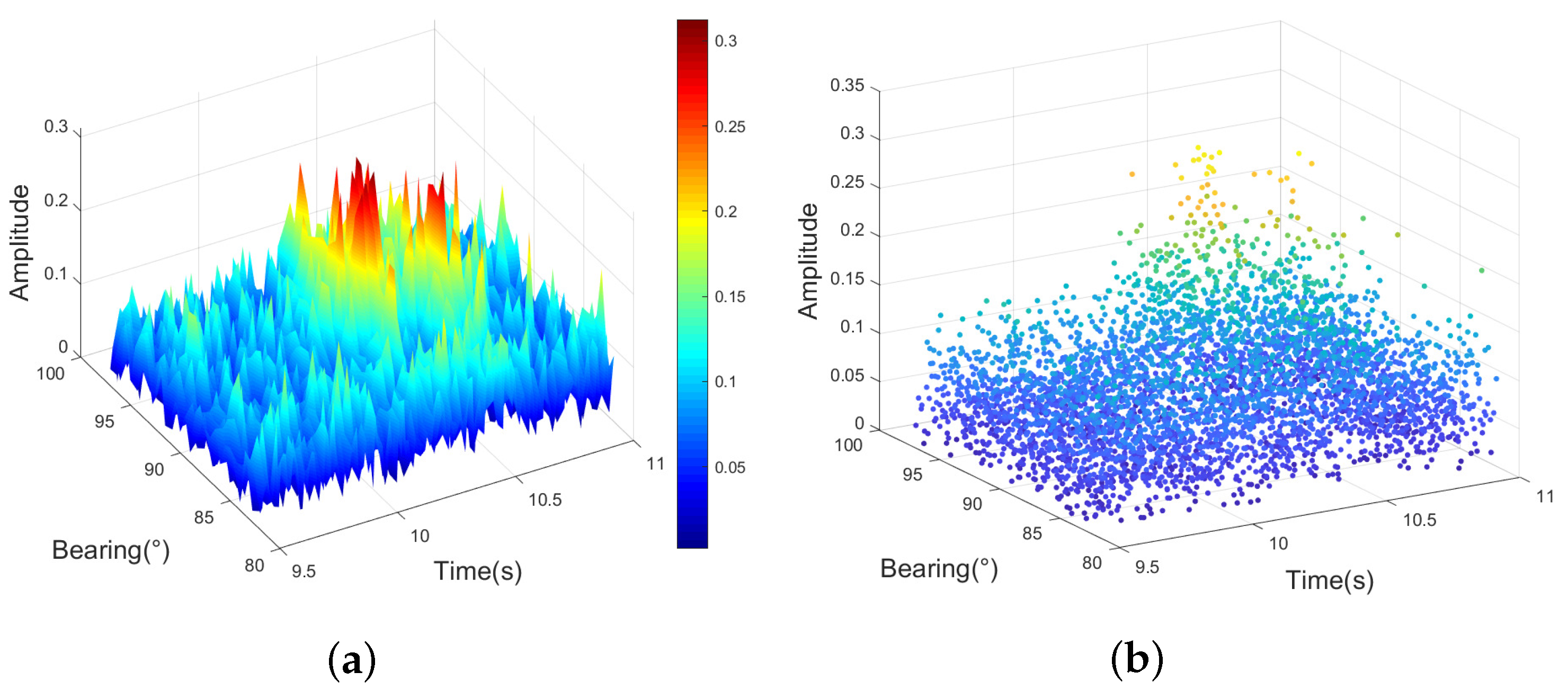
From Figure 4, it can be observed that multiple measurement information is generated when observing a target, including information related to the target to be tracked as well as false alarms. The reasons for generating multiple measurement information are as follows:
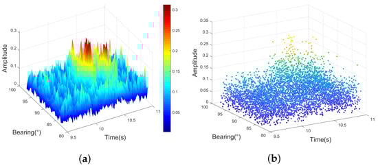
Figure 4.
Active sonar echo: (a) bearing–time–amplitude result; (b) different amplitude measurements.
(1) The main lobe width formed by the beamforming algorithm.
(2) Existence of multipath phenomena in time.
(3) Reverberation and interference of ocean noise in shallow water.
Traditional localization and tracking algorithms typically use the highest amplitude point as the target position. A three-dimensional scatter plot of detection results is shown in Figure 4, where it can be seen that there are many points with high amplitude, and only using the point with the highest amplitude can lead to significant errors. As shown in Figure 5, the true position is at the bearing of 91° with the relative time of 10.0600 s, while the highest amplitude position is at the bearing of 89.5° with the relative time of 10.3040 s. There is a deviation of 1.5° in bearing and 0.2440 s in relative time between the true position and the highest amplitude position, which translates into a distance deviation of 373.32 m. It can be seen that the deviation error is quite large, which will affect the tracking severely.
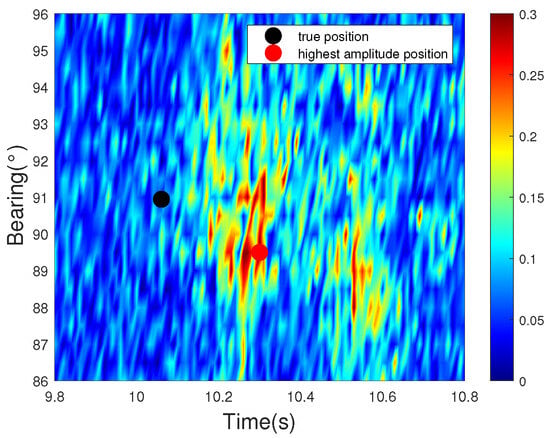
Figure 5.
Comparison between the position with the highest amplitude and the true position.
This paper utilizes the spatial clustering results obtained to track the target. Treating the spatial clustering results as multiple measurement points generated by surface reflections of the same target, the multiple measurements originating from the target provide more target information. Including the motion information and physical characteristics of the target, such as amplitude and Doppler information. The amplitude information is the result of the matched filter. When using Doppler-sensitive signals, as shown in Figure 6, the target Doppler information can be obtained through signal replication [31]. Specifically, Doppler-sensitive signals and different matched filters are first used to estimate the Doppler shift. Subsequently, a two-dimensional interpolation is applied to interpolate and compensate for the received signals. Thereby, the Doppler information of the target is acquired. During the interval between adjacent data snapshots, the Doppler frequency of the target does not change a lot, which represents a relatively stable characteristic. Additionally, different targets possess distinct Doppler frequencies, which are different from those of other targets and clutters.
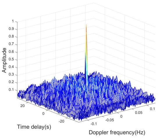
Figure 6.
Ambiguity function of a Doppler-sensitive signal.
3. Methods
This section first introduces the traditional PDA algorithm and analyzes the various parameters within the PDA algorithm. Based on this, a multi-information-assisted PDA algorithm for bistatic active sonar target tracking is proposed. First, we explore the feasibility of using amplitude and Doppler information from active sonar echo signals in the tracking process. Then, this paper presents the calculation algorithm for the association probability of the multi-information-assisted PDA algorithm and provides a complete algorithm framework.
3.1. Probabilistic Data Association
The traditional nearest-neighbor association algorithm follows the principle that the target should consider only one measurement point within the gating region of the target to be generated by the target. However, the PDA algorithm holds that all measurement points within the gating region cannot be ruled out as potentially generated by the target, although the probability originating from the target varies. Therefore, this algorithm comprehensively considers all measurement points within the gating region, calculates the association probability between each measurement point and the target, and then obtains the weighted sum of the measurements to update the position of the target at the current time.
There are amounts of measurements at time k that fall within the correlation gate of the target. The association probability is the ith measurement that falls within the correlation gate of the target. The association probability generated by the true measurement of the target is as follows:
where is the complete set of measurements at time k, indicates the event that the measurement points were generated by the target. The sequence of measurement sets accumulated up to time is described as . also satisfy the following conditions:
In active sonar tracking, the following assumptions are made for the PDA algorithm:
(1) The detection probability of the target is , where represents the probability of detecting at least one measurement originating from the target;
(2) Multiple measurements are generated within the target range in each scan cycle;
(3) A measurement may originate from the target or noise;
(4) Measurements are uniformly distributed within the detection range.
Therefore, the motion state of the target can be obtained using the following equation:
where represents the predicted motion state of the target at time k based on the motion state of the target at time , which is the target motion state update value corresponding to event . Additionally, is the kalman gain, represents the innovation associated with the ith measurement track, and represents the combined innovation. Therefore, the core of the PDA algorithm lies in calculating the combined innovation to estimate the motion state.
According to the Bayes theorem, Equation (7) can be transformed into:
where represents the likelihood function of event , and represents the conditional probability of event . Let be the ith measurement point trace of . According to the assumption (3), the probability density function of the measurement traces associated with the target can be derived as shown:
where denotes the probability that the real measurement point trace generated by the target to be tracked falls into the relevant wavegate of the target at the current moment, which is generally taken as 1. denotes the new interest covariance matrix. Additionally, is the assumption that the positions of the measurement follow a normal distribution.
According to the assumption (4), the probability density function of all false point traces can be obtained. Finally, the expression in Equation (11) is derived using Equation (13) and the probability density function of false point traces.
where denotes the number of false measurement traces appearing in the unit area, indicates the associated gate, and denotes the number of false measurement traces appearing in the relevant wavegate. When the false measurement points follow a Poisson distribution, the conditional probability of event is:
The association probability with a Poisson distribution is given by:
A further expansion of Equation (15) yields the following:
The probability that there are no measurement tracks generated by the target at time k is:
The PDA algorithm calculates the combined innovation using all measurements that fall within the correlation gate and the probability that each measurement is generated by the target. The formula for calculating the combined innovation is the following:
Kalman filter (KF) is an optimal estimation algorithm widely used for state estimation in dynamic systems, and it estimates the system state in a recursive manner with incomplete and noisy data. The main steps of KF include prediction and update. According to the calculation process of the KF, we need to compute the combined innovation and update the motion state of the target. The covariance matrix of the motion state error of the target is:
where and are:
3.2. Multi-Information-Assisted Probabilistic Data Association
The traditional PDA algorithm only uses the position information of the measurement points to calculate the association probability between each measurement point and the target. To comprehensively consider the association probability under AUV-deployed bistatic sonar constraints, this paper proposes incorporating features such as the target echo amplitude and Doppler frequency measured during the tracking process into the calculation of the association probability. The specific process is shown in Figure 7. When tracking multiple targets in complex environments, if the tracking gates of multiple targets do not intersect, or if there are no measurements in the overlapping region of the tracking gates, we can consider multi-target data association as single-target data association to solve the issue. This simplification aligns with the computational limitations of embedded AUV processors. However, if measurements fall into the overlapping region of target tracking gates, the PDA algorithm has limitations.
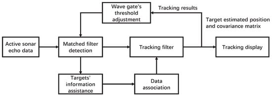
Figure 7.
Main framework of the proposed tracking algorithm.
Traditional association gates only use target position information to predict the range of possible observations, leading to computational complexity and potential false tracks, especially in low-amplitude situations or densely cluttered regions. In addition, when the trajectories of multiple targets are close or intersect, the association gates of adjacent targets may overlap. If measurement points enter the overlapping area, track merging or tracking errors may occur. This paper incorporates target position, echo amplitude, and Doppler frequency into the observation vector of target, constructing a multi-information-assisted algorithm. Using multiple information can filter measurement points in overlapping regions effectively. As shown in Figure 8, the target position and echo amplitude information are used to estimate the target position, while the Doppler information constrains valid measurements. With the assistance of multi-information, measurement points that were originally in overlapping regions of two association gates can be associated correctly.
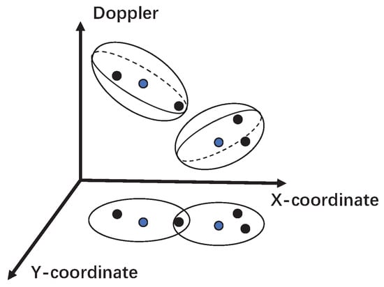
Figure 8.
Data association under different Doppler frequencies. The blue points in the figure represent the predicted observation values of the target, and the black points represent other measurement points.
From Equation (10), we can obtain the probability that the th measurement track that falls within the correlation gate is generated by the true measurement track of the target, which is mainly composed of two parameters: (1) the likelihood function of event ; (2) the conditional probability of event Among them, only the likelihood function is related to the association probability between the measurement track and the target to be tracked. Therefore, the likelihood function of event is:
In Equation (22), reflects the assumption that the positions of the measurement tracks follow a normal distribution, which can assume that the conditions for the PDA algorithm hold true. However, this likelihood function only utilizes position information from the measurement tracks. As is a constant, only influences the final value of . Therefore, the value of can be understood as the correlation coefficient between the nth measurement track and the target being tracked. Then, we can denote this value as :
Based on the previous derivation, we know that the parameters and are determined solely by position. To simultaneously utilize position and feature information to correct the correlation coefficient between the ith measurement track and the target being tracked, it is necessary to compute the correlation coefficient between the amplitude and Doppler frequency contained in the ith measurement track and the expected amplitude and Doppler frequency of the target at time k. Then, we can calculate the corrected correlation coefficient between the ith measurement track and the target being tracked by integrating all the information.
The PDA algorithm assumes that the correctly measured tracks follow a normal distribution in the position space. From experimental observations and theoretical analysis, the expected values and of the amplitude and Doppler frequency estimated for the target at time k are obtained. A Gaussian probability density function is established to obtain the correlation coefficient between the Doppler frequency and the amplitude for the ith measurement track. So we can obtain the correlation coefficient of the amplitude and the Doppler frequency for the ith measurement track:
where and represent the standard deviations of a and f. Suitable values for and are set based on the weights of the amplitude and Doppler frequency in the process of calculating the relative combined correlation coefficient between the measurement track and the target to obtain more accurate results. By adjusting the variance and mean, we can obtain three correlation coefficients with different parameters. Since tracking is required in multi-target scenarios, the Doppler-related frequency will have a larger weight, while amplitude and position information will have smaller weights. After calculating the correlation coefficients of the amplitude and Doppler frequency for the nth measurement track, the relative combined correlation coefficient between the nth measurement track and the target can be obtained using:
From Equation (26), we can conclude that in general, when the Doppler frequency cannot be obtained, the filter degenerates into an amplitude information-assisted PDA filter, where ; when both fail, it degenerates into a PDA filter, where .
From Equation (22), it is evident that the relative probability of the target not generated by the measurement tracks at time k is obtained solely based on position information. Therefore, when calculating the relative probabilities that each measurement track is associated with the target at time k, it is necessary to adjust the magnitude of . Let the adjusted relative combined correlation coefficient be . Then, needs to satisfy that the relative magnitudes among all remain unchanged and also satisfy:
Therefore, we need to correct :
By replacing with , we obtain the new . Then, we determine the association probability that the ith measurement track at time k is generated by the target being tracked, integrating both positional and feature information:
Similarly, after integrating positional and feature information, change to:
Using the newly obtained association probabilities, we calculate a new combined innovation, which is then used to update the improved state estimate and state the covariance matrix of the target. This process incorporates the latest association information at each step, making the state estimation more accurate. Additionally, as the association probabilities are updated, the system becomes better equipped to handle uncertainties in dynamic environments and reduce estimation errors. This multi-information state update method enhances the robustness of the algorithm, addressing complex motion patterns, and ensuring tracking stability and accuracy in practical applications.
4. Experiments
This section validates the performance of the algorithm through simulation experiments. First, the performance of the algorithm is verified under different measurement densities. Additionally, experiments are conducted in two scenarios with multiple targets to verify the effectiveness of the algorithm. The first is that the three targets have straight paths and intersect, and the second is that the three targets converge from the far end and then separate. These two scenarios are the most common scenarios when AUVs track targets. Finally, the effectiveness of the algorithm is verified in sea trial data.
4.1. Simulation Results Under Different Measurement Densities
We assume that a series of target measurements have been acquired through the bistatic active sonar system in AUV, including positional coordinates (bearing, range), echo amplitude, and Doppler shift. This system enables efficient data collection in shallow water, providing multidimensional inputs for subsequent multi-information-assisted tracking algorithms.
Firstly, the performance of the multi-information-assisted PDA algorithm in tracking was simulated under different measurement densities. The measurement densities were , , and . In addition, the target detection probability is 1, and the gate probability is 0.99. Considering the uniform linear motion of the target in the plane, the motion equation can be expressed as:
where represents the target state vector at time k, is the state transition matrix, and represents the process noise. The performance metric used for comparison is the root mean square error (RMSE).
where N is the number of Monte Carlo (MC) simulations.
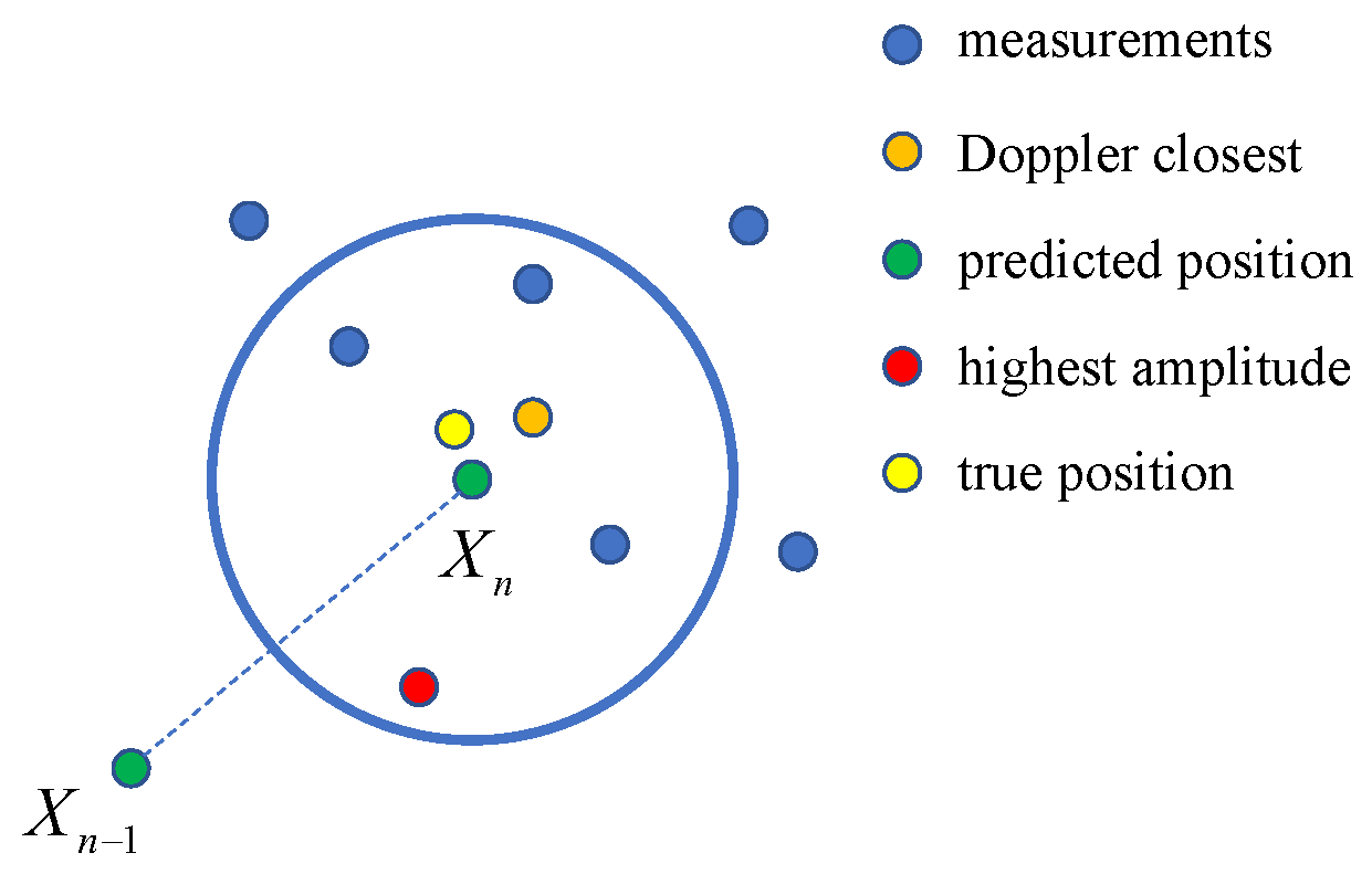
The data modeling is depicted in Figure 9, where the measurement positions of the target follow a uniform distribution. The amplitude and Doppler observations of different measurements follow Gaussian distributions. The orange points represent the estimated Doppler frequency closest to the true Doppler frequency, indicating proximity to the true value (the yellow points). The red points represent the highest amplitude points, set at distances far from the true position. The blue points represent the remaining measurement points. Finally, the green points represent the predicted results within this ping.
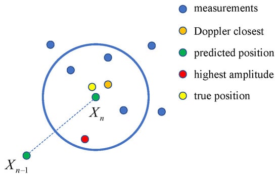
Figure 9.
The spatial position of measurements.
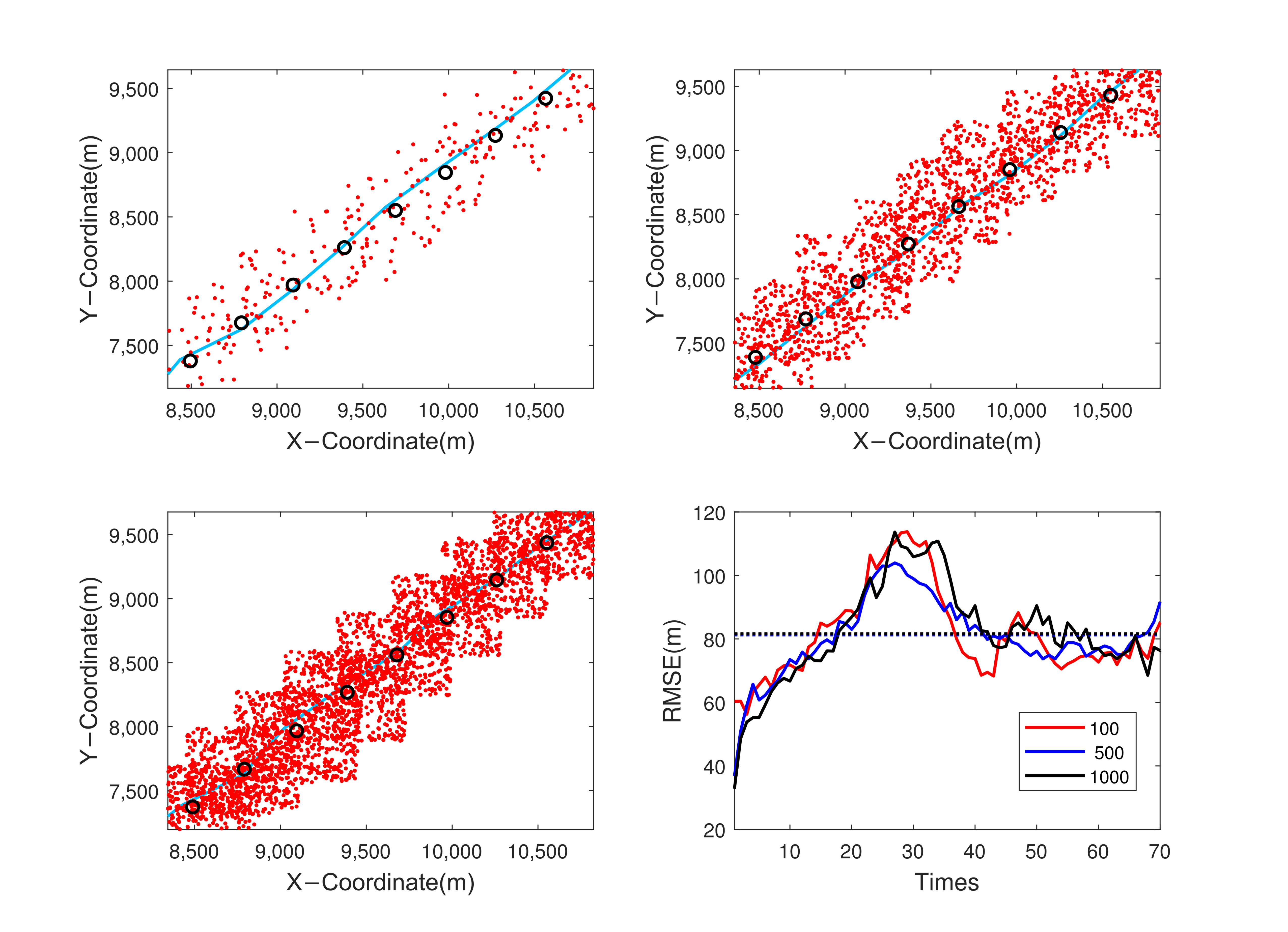
The tracking results and the RMSE are shown in Figure 10. It shows that the position errors of the algorithm reach a stable state shortly after the start of tracking. The RMSE generated by the multi-information-assisted PDA algorithm converges to a smaller stable value. With an increase in measurement density, the change trend of RMSE produced by the multi-information-assisted PDA algorithm with the increase in tracking steps does not show significant changes, eventually converging to a smaller value. Moreover, the multi-information-assisted PDA algorithm continues to exhibit good tracking performance, even in environments with higher measurement density.
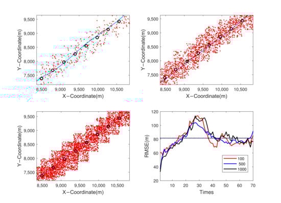
Figure 10.
Results of different measurement densities. Red points are measurements, the line is the true trajectory of target, and the black circles are the estimated positions of the algorithm. Besides, the dotted line in the RMSE results represents the average RMSE of these algorithms.
4.2. Multi-Target Simulation Scenario 1
IMM is a filtering algorithm based on multiple models, used to track the state of the target under different motion modes. It combines various motion models (such as constant velocity (CV), coordinated turn (CT), etc.) and fuses the outputs of different models through interactive weights to improve tracking accuracy. However, its computational complexity is relatively high, as parallel computation of multiple models increases the burden.
During multi-target tracking, it is easy to encounter association biases at trajectory intersections, resulting in the misassociation of measurements from target A to target B (or vice versa), causing the RMSE to fail to converge. Taking three uniformly moving targets with intersecting trajectories in a two-dimensional scenario as tracking objects, the following algorithms are compared in terms of performance: KF, conventional target tracking (only using the highest amplitude point for tracking), PDA algorithm (utilizing only positional information for data association in the PDA algorithm), AI-PDA algorithm (assisted data association using amplitude information), and MI-PDA algorithm (assisted data association using both amplitude and Doppler information). Since the target positions obtained from active sonar have been converted into X and Y coordinates, these coordinates are used as observations and translated into a linear problem. Therefore, CV-KF is employed for filtering in all four algorithms.
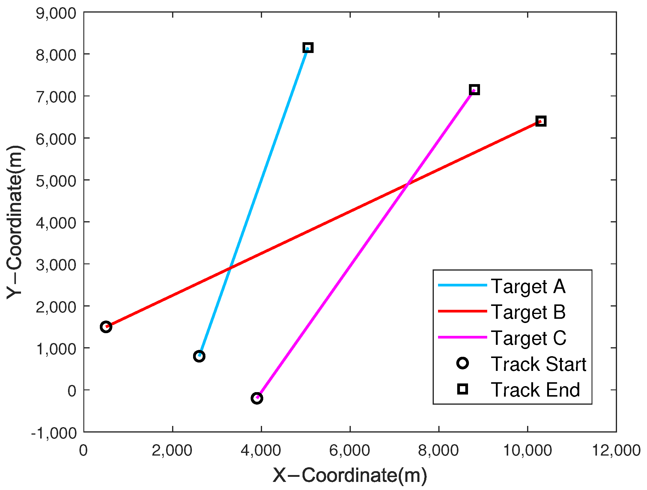
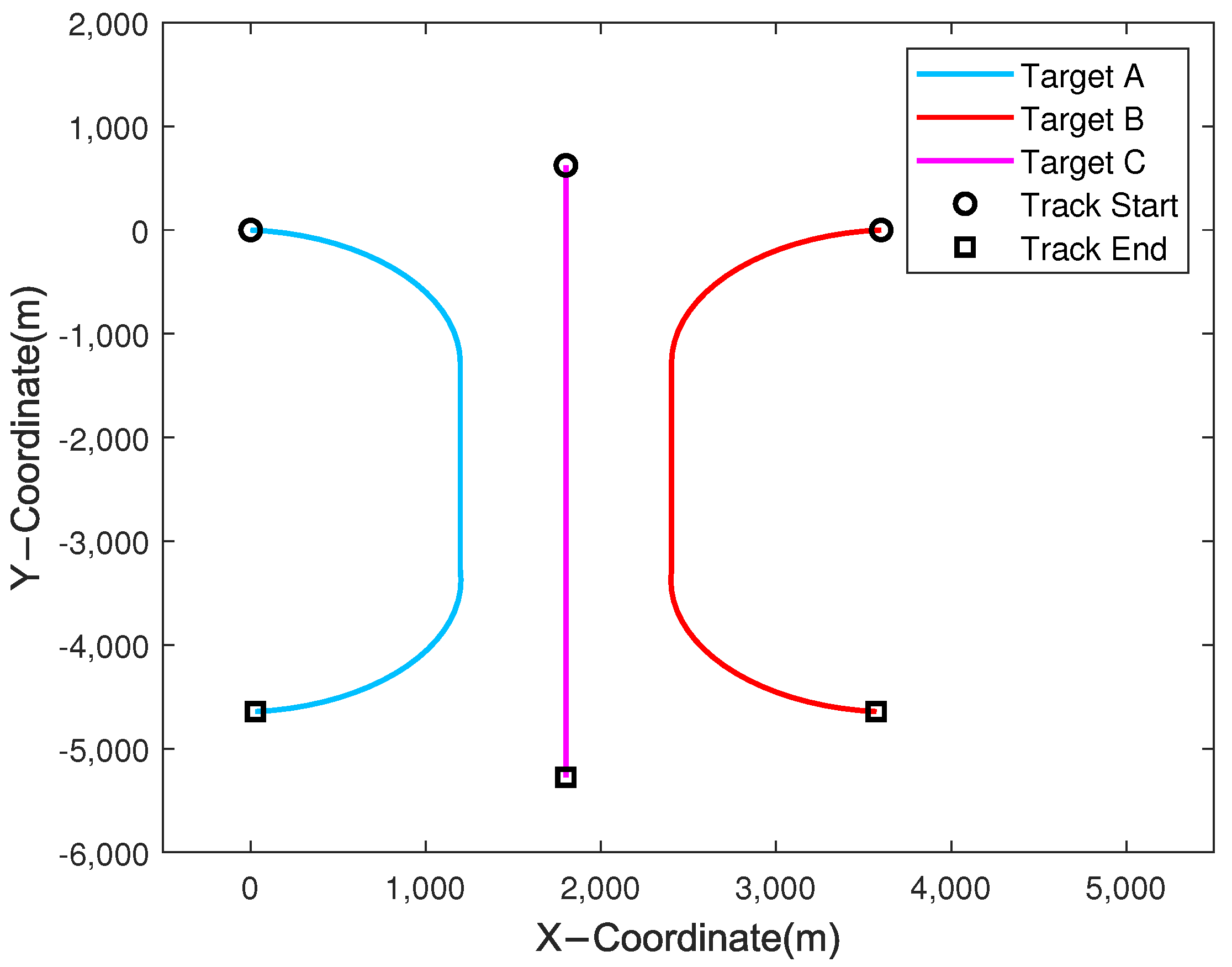
The experimental ground truth for tracking three intersecting targets is illustrated in Figure 11. Three targets experience trajectory intersections at different times. Then, targets A and B coincide in the 15th ping of data, while targets B and C coincide in the 35th ping of data. The targets move at constant velocity, and the measured positions of the targets follow a uniform distribution. We assume that we can harvest the amplitude and Doppler information for each measurement point. Based on the experience of previous sea trials, this paper selected the measurement density to be , and the amplitude and Doppler observations of different measurements follow Gaussian distributions. Additionally, different targets have different expected values of amplitude and Doppler information.
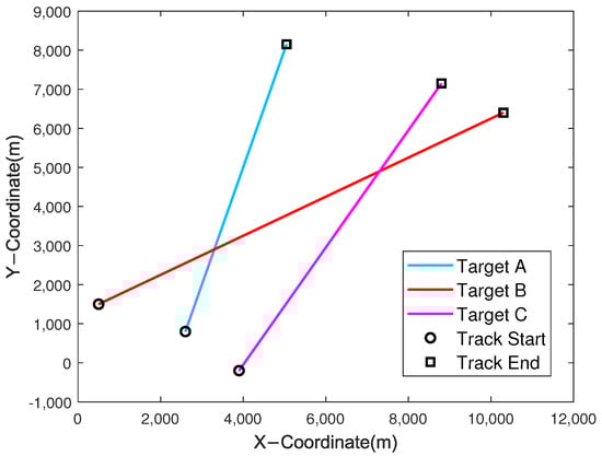
Figure 11.
True target trajectories of scenario 1.
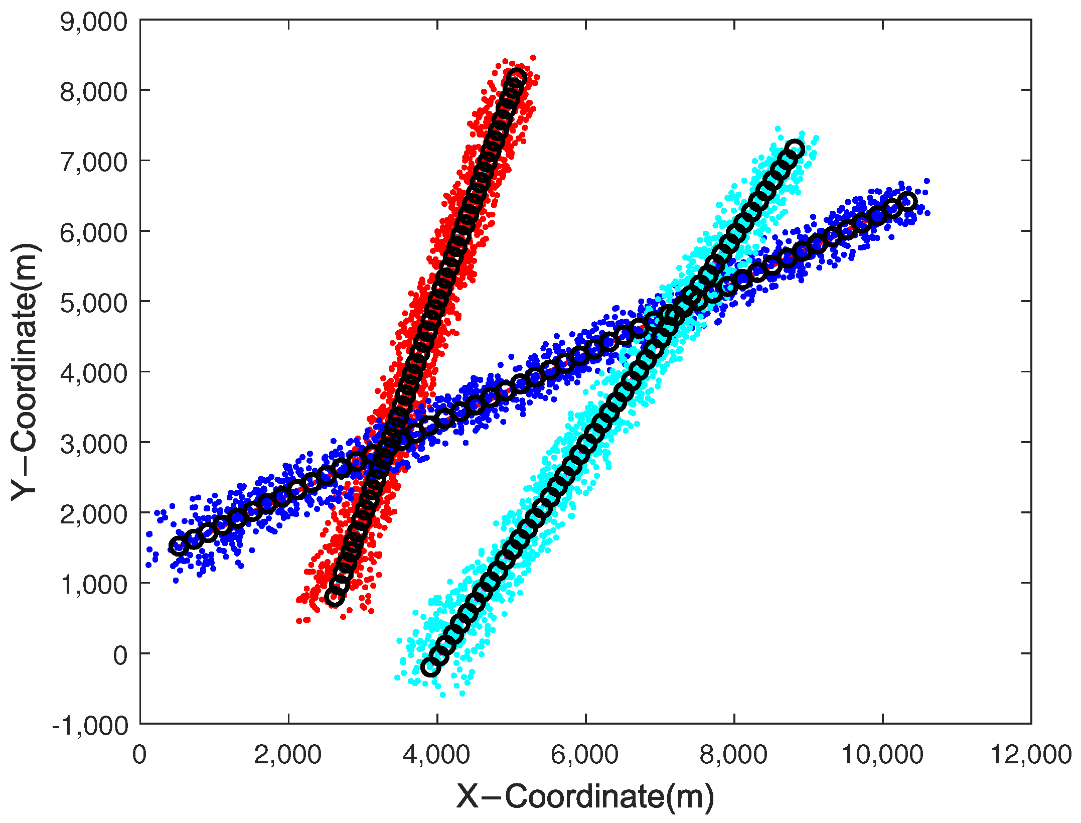
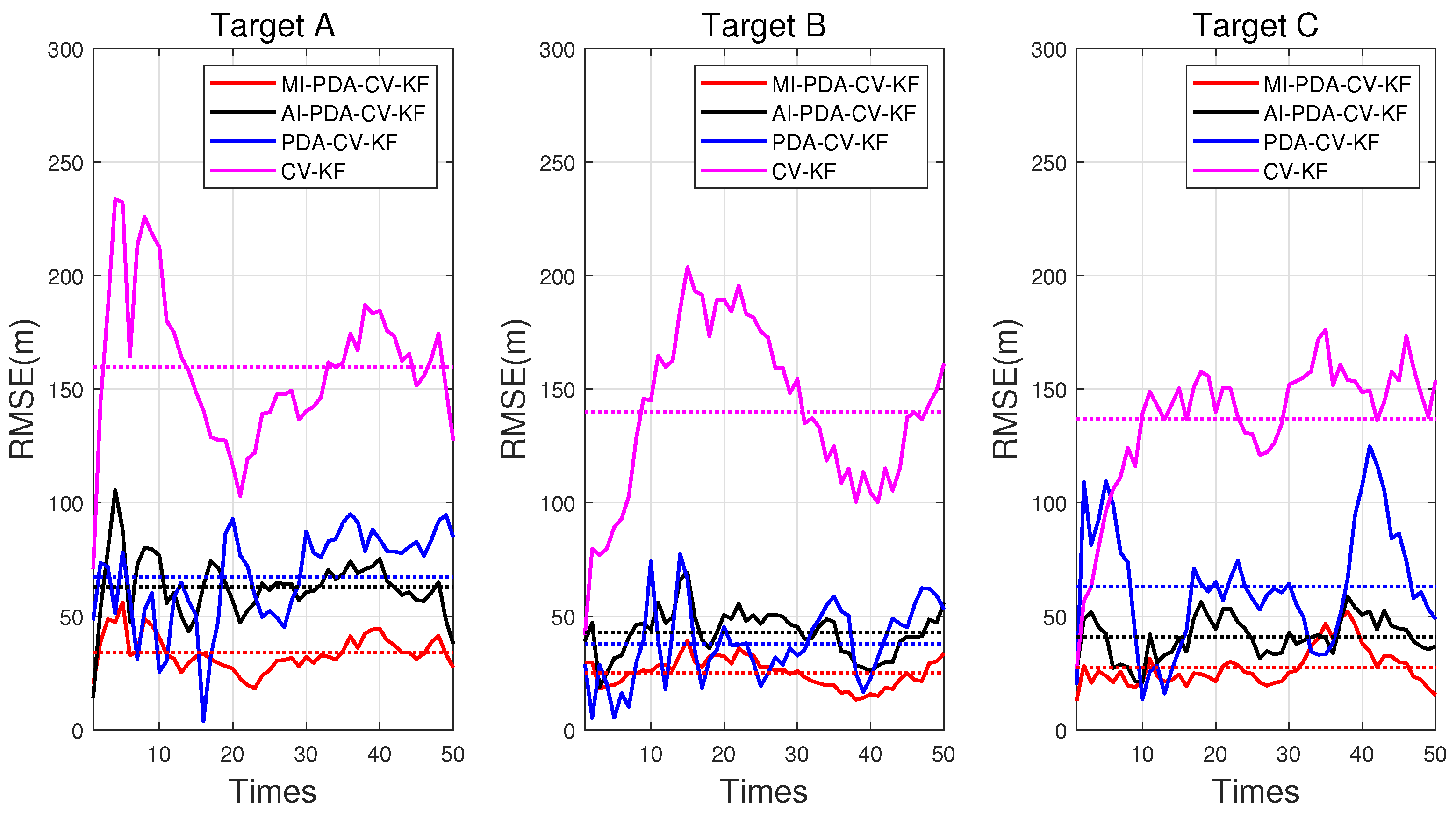
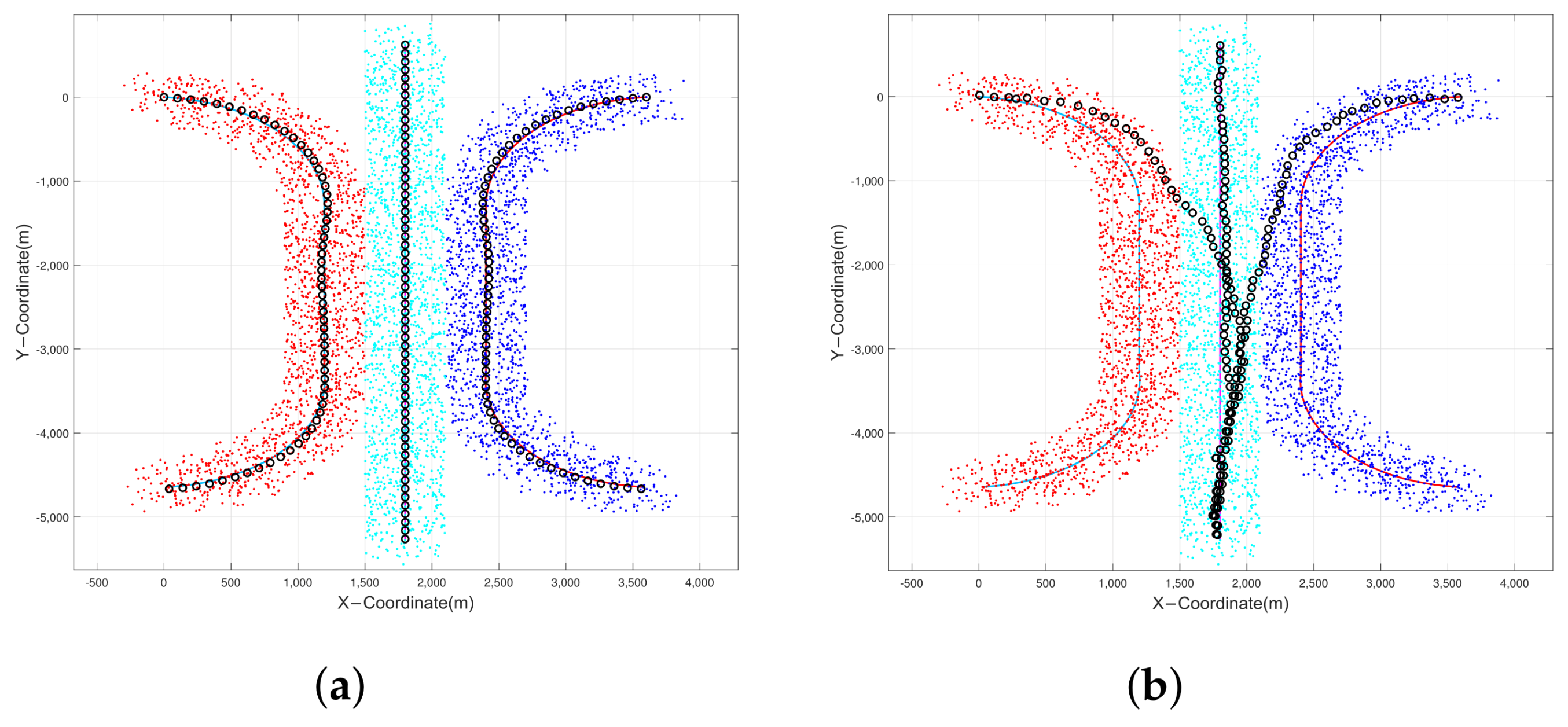
As shown in Figure 12, the filtering results of the multi-information-assisted PDA algorithm are very smooth, and no association errors occurred. With the assistance of Doppler, the multi-information-assisted PDA algorithm performs better in multi-target tracking tasks in complex clutter scenarios. Figure 13 analyzes the RMSE of the tracking results for three targets. The performances are obtained from 200 MC trials. To make the comparisons more meaningful for all algorithms, the same random measurement streams are used in each MC trial. It can be seen that compared with the traditional PDA algorithm, the multi-information-assisted PDA algorithm shows significant performance improvement. Specifically, the RMSE of the CV-KF, PDA-CV-KF, AI-PDA-CV-KF, and MI-PDA-CV-KF algorithms are 145.4413 m, 56.0817 m, 48.8768 m, and 28.8060 m. Additionally, significant improvements are observed even with single-amplitude assistance, and further enhancements are achieved with the addition of Doppler information. This indicates that additional information constraints can reduce the bias caused by considering only position information, demonstrating the effectiveness of the improvements to the PDA algorithm.

Figure 12.
Estimated target trajectories (MI-PDA-CV-KF) of scenario 1. Different color points are measurements of different targets, the lines are the true trajectories of targets, and the black circles are the estimated positions.

Figure 13.
The RMSE results of the tracking algorithms. Besides, the dotted line in the RMSE results represents the average RMSE of these algorithms.
4.3. Multi-Target Simulation Scenario 2
Then, we simulate the scenario in which multiple target trajectories converge. Figure 14 shows the trajectories of targets in scenario 2, three targets experience an ambiguous mixture simultaneously. The measured positions of the targets follow a uniform distribution, with a measurement density of . The amplitude and Doppler observations of different measurements follow Gaussian distributions. In this scenario, the three targets move along determined trajectories. Initially, the targets approach each other, then they move parallel at close range, and finally, they move away from each other. Additionally, the main parameters used in scenario 2 are the same as in scenario 1. There are 200 MC trials in the simulation. The three motion models are used in this section: Model 1 is the CV model, and Model 2 and Model 3 are the CT models. The corresponding state transition matrices are as follows:
where the angular frequency of turning is , and T is the sampling interval. Initial transfer probability . The Markov transition matrices between the models are as follows:
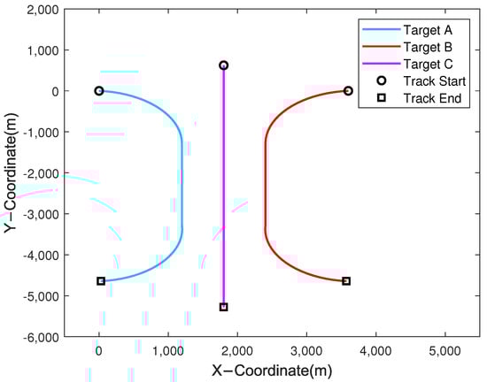
Figure 14.
True target trajectories of scenario 2.
The RMSE of position tracking for targets A, B, and C was compared between traditional algorithms and the algorithm proposed in this paper during the track maintenance phase. The target position estimates from one MC run of the MI-PDA-IMM-KF algorithm and the PDA-IMM-KF algorithm are shown in Figure 15. It can be observed that the target position estimates from MI-PDA-IMM-KF are consistently close to the true values. However, because of track merging, the performance of PDA-IMM-KF is not ideal. The uncertainty association of track measurement occurs when the targets are close in distance, leading to the track coalescence problem in PDA-IMM-KF. Moreover, it is difficult for the filter to track the targets even when they are away from each other.
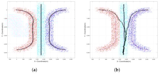
Figure 15.
Estimated target trajectories of scenario 2: (a) MI-PDA-IMM-KF; (b) PDA-IMM-KF. Different color points are measurements of different targets, the lines are the true trajectories of targets, and the black circles are the estimated positions.
Figure 16 shows the RMSE for the four algorithms. During the parallel moving stage, due to the influence of each other, the position error of the PDA-IMM-KF algorithm becomes higher. At the same time, the IMM-KF and AI-PDA-IMM-KF algorithms have a smaller error in position estimation, but the MI-PDA-IMM-KF algorithm is lower. The reason for this is that the amplitude and Doppler information play a role, and different Doppler frequencies of different targets have enhanced the tracking accuracy. Thus, once no tracking loss occurs, it has better performance in position estimates. The PDA-IMM-KF algorithm has failed to track and filter, and the RMSE of the IMM-KF, AI-PDA-IMM-KF, and MI-PDA-IMM-KF algorithms are 149.0429 m, 68.0819 m, and 43.8129 m. It can be seen that the proposed algorithm is more efficient than others.
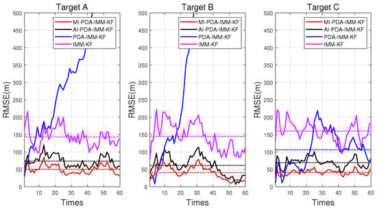
Figure 16.
The RMSE results of the tracking algorithms. Besides, the dotted line in the RMSE results represents the average RMSE of these algorithms.
4.4. Sea Trial Results
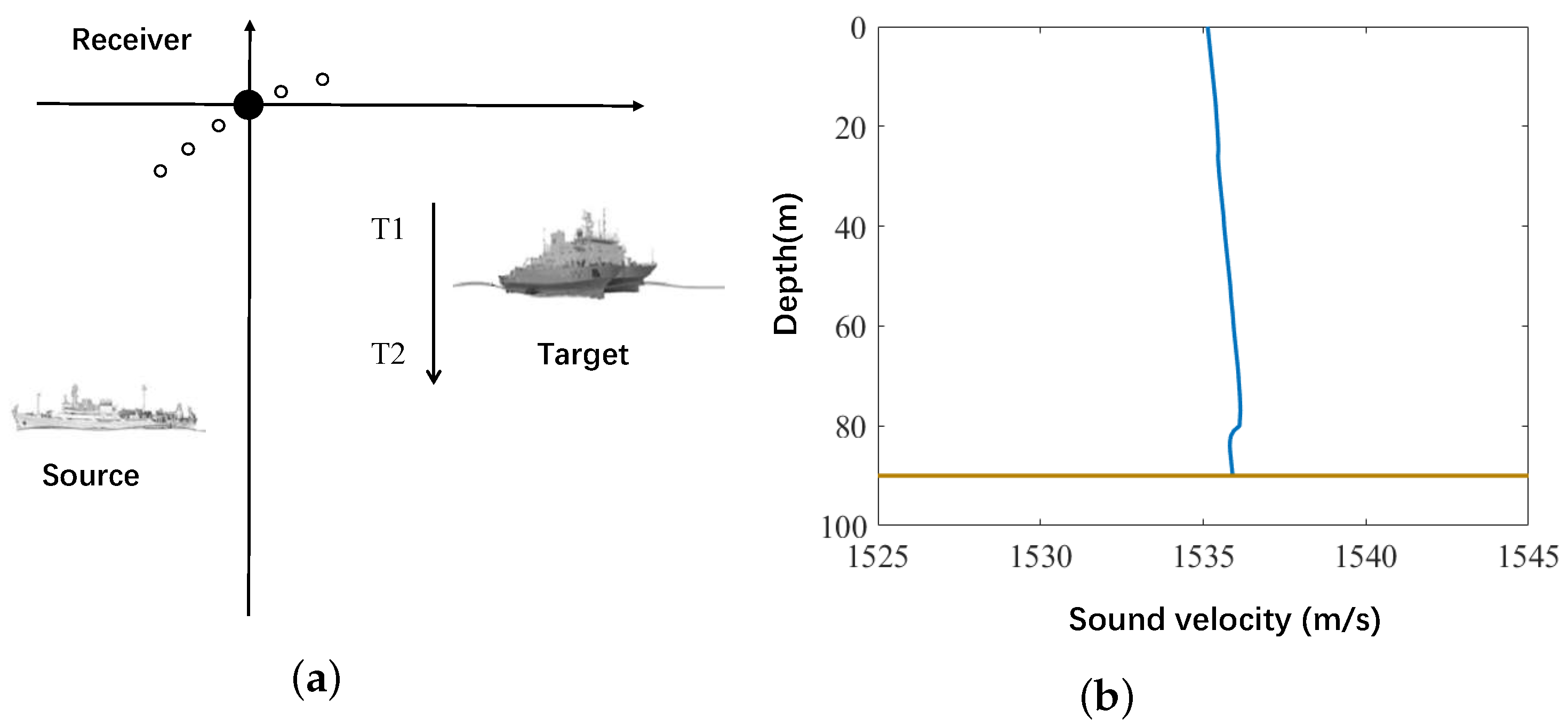
In October 2022, a bistatic active sonar experiment was conducted in the South China Sea. The experimental setup and sound velocity profile are shown in the following Figure 17. The experimental environment of this paper is shallow water with a water depth of 90 m. In the experiment, a large research vessel served as the target, while another vessel used a towed acoustic source to transmit signals. The towed acoustic source was deployed at a depth of 50 m and emulated an AUV that transmitted signals in shallow water during the experiments. The receiver, a horizontal array fixed on the seabed, was configured to simulate the towed array of an AUV operating in shallow water. In addition, the two-way propagation distance between the transmitter, target, and receiver ranged from 15 km to 18 km. The transmitted signal was a linear frequency modulation (LFM) signal with a bandwidth of 100 Hz. Additionally, the duration of the transmitted signal was 20 s and was transmitted every 2 min. During the experiment, the target moved in a straight line, but due to factors such as waves, there were errors in the heading, and the movement was not entirely linear. The bearing–time result of one echo is shown in Figure 18. The results obtained from the figure are consistent with the description in Section 2.2, the main lobe formed by the beamforming algorithm, and the multipath can be observed.
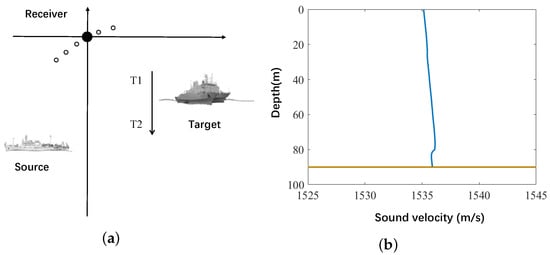
Figure 17.
Bistatic active sonar experiment in October 2022: (a) experiment positions; (b) sound speed profile.

Figure 18.
Bistatic active sonar detection result.
The shallow water environment leads to a significant spatial spread of target echoes and increased noise interference in bearing–time figures. The LFM signals are insensitive to Doppler shifts, which means that Doppler information cannot be utilized in the sea trial data. The long return interval introduces uncertainties in the motion of the target and challenges in data update. The medium to long ranges amplify the effects of propagation loss, reverberation, and the geometric dilution of precision in bistatic localization, further increasing the difficulty of tracking. These factors highlight the necessity of integrating the multi-information algorithm to better accommodate the practical scenarios of AUVs.
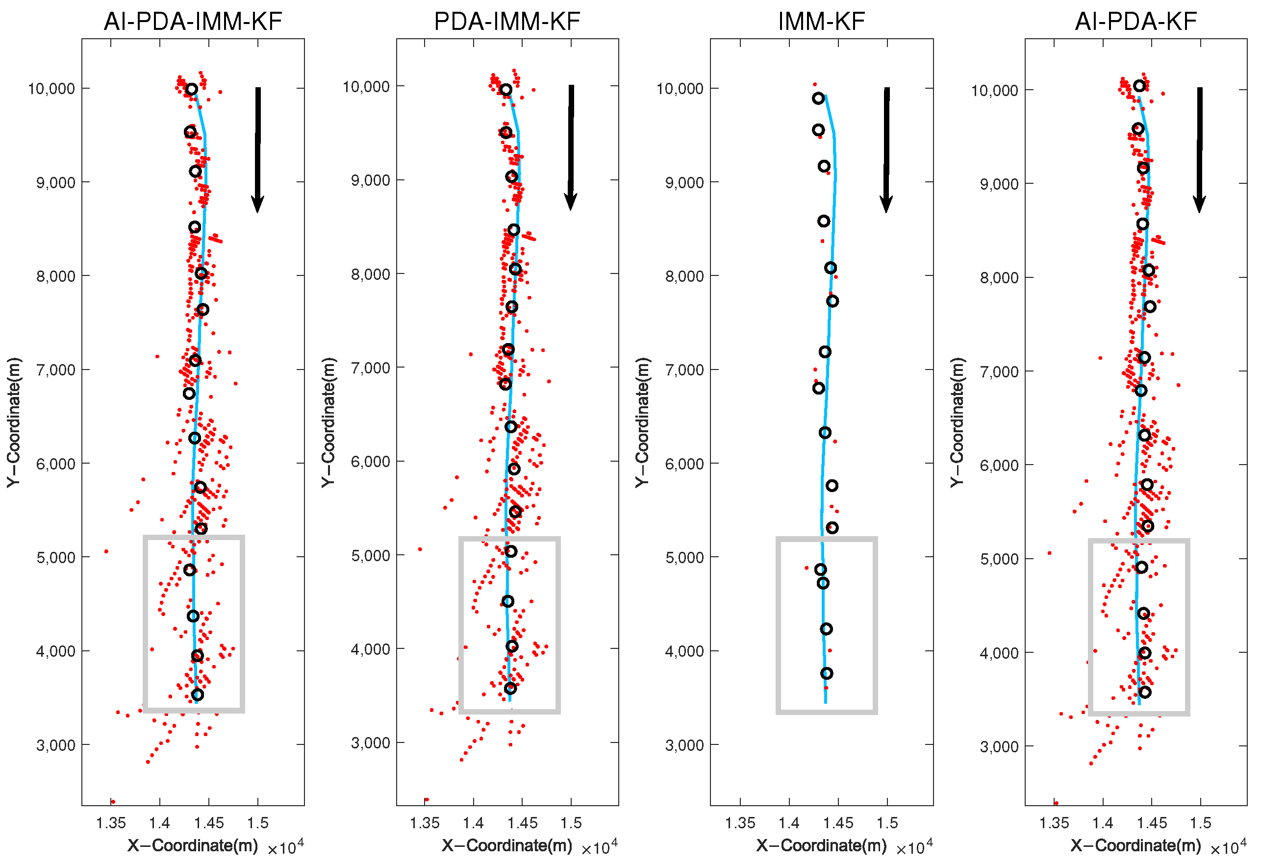
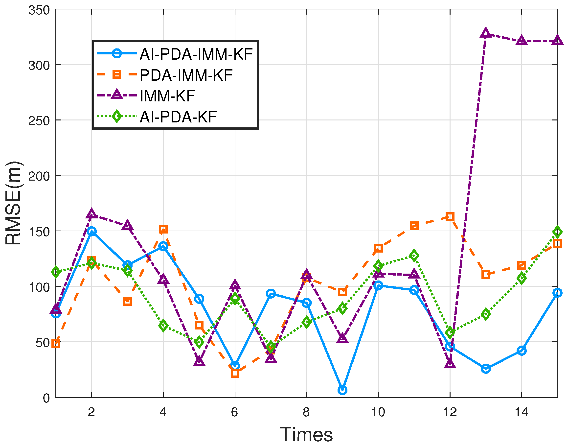
Since the signal used in the experiment was an LFM signal, which is insensitive to Doppler effects, only the amplitude information could be obtained from the target measurement data. Thus, the AI-PDA-IMM-KF algorithm, the PDA-IMM-KF algorithm, and the traditional positioning IMM-KF algorithm were compared and analyzed. In addition, we added the AI-PDA-KF algorithm to measure whether the IMM is effective. The tracking trajectories and RMSE are shown below: From Figure 19, it can be observed that the curve of the AI-PDA-IMM-KF algorithm is the smoothest and closest to the true values. Within the highlighted region, it aligns more closely with the GPS trajectory compared to other algorithms. In contrast, the trajectory of traditional positioning algorithms deviates significantly from the actual trajectory, demonstrating poorer performance. The RMSE curves shown in Figure 20 indicate that the proposed AI-PDA-IMM-KF algorithm achieves the lowest positioning error among the compared methods, followed by the AI-PDA-KF, PDA-IMM-KF, and traditional IMM-KF algorithms. As shown in Table 1, the traditional IMM-KF algorithm yields an average RMSE of 136.8948 m, while the PDA-IMM-KF algorithm reduces this error to 104.1703 m, representing an improvement of 32.7245 m or approximately 23.90%. The AI-PDA-KF algorithm, which integrates the amplitude information but excludes the IMM framework, achieves an RMSE of 92.0889 m. This result demonstrates the effectiveness of incorporating amplitude information into the measurement process. In particular, the proposed AI-PDA-IMM-KF algorithm further reduces the RMSE to 79.2145 m, outperforming the AI-PDA-KF algorithm by 12.8744 m (a 13.99% improvement) and the PDA-IMM-KF algorithm by 24.9558 m (a 23.95% improvement). Compared to the traditional IMM-KF algorithm, the total improvement reaches 57.6803 m or 42.13%. These results collectively highlight the benefit of integrating amplitude information, probabilistic data association, and the IMM framework to achieve substantial gains in tracking accuracy.
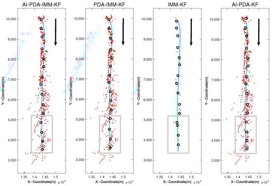
Figure 19.
Estimated target trajectories. Red points are measurements of the target, the blue lines are the true trajectories of targets from GPS, and the black circles are the estimated positions. The arrows in the figures indicate the direction of movement of the target, and the gray frames are the end of the trajectories, where the tracking results of each algorithm differ the most.
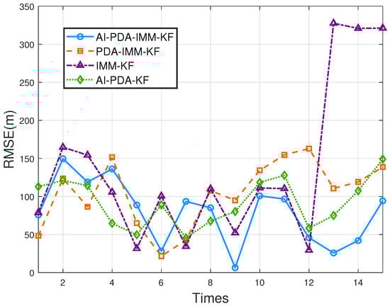
Figure 20.
The RMSE results of different algorithms on the sea trial data.

Table 1.
The average RMSEs of different algorithms.
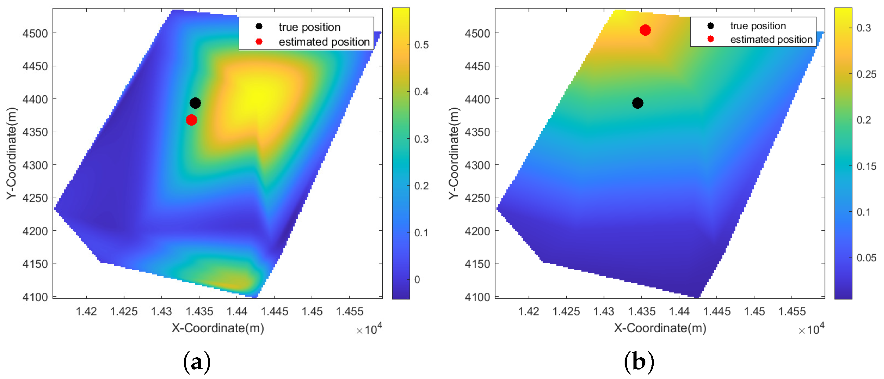
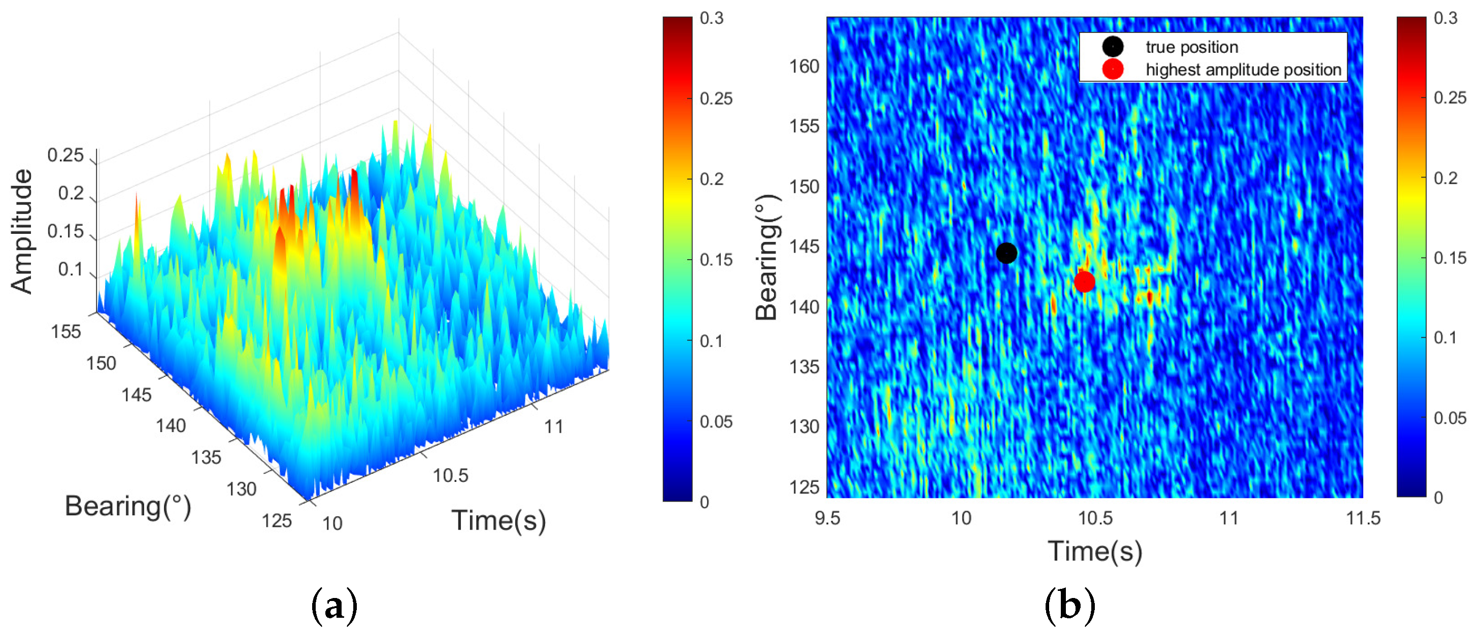
In Figure 20, we observe that the RMSE of the 12th ping data is relatively low after applying the IMM-KF algorithm. Figure 21 illustrates that the point with the highest amplitude is very close to the true position, resulting in a better tracking performance of the IMM-KF algorithm. However, the PDA-IMM-KF, AI-PDA-KF, and AI-PDA-IMM-KF algorithms utilize measurement bearings from 120° to 140° and estimate positions further from the true location. For the 13th ping data in Figure 22, the RMSE increases with the IMM-KF algorithm because the highest amplitude point is approximately 10° away from the true position. After data association with the PDA-IMM-KF, AI-PDA-KF, and AI-PDA-IMM-KF algorithms, the estimated position lies between two regions, demonstrating the effectiveness of the PDA method. From Figure 23, we can see that after incorporating amplitude information, the AI-PDA-IMM-KF and AI-PDA-KF algorithms calculate association probabilities that are constrained by amplitude, making them more aligned with the true positions. In contrast, the results of the PDA-IMM-KF algorithm rely solely on position information, making them more susceptible to the influence of other factors.
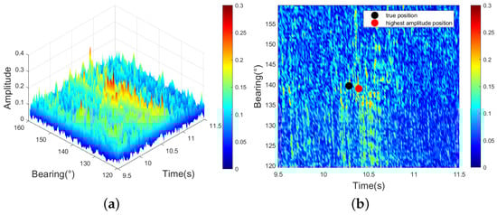
Figure 21.
The 12th ping data: (a) bearing–time–amplitude result; (b) bearing–time result.
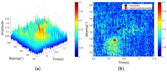
Figure 22.
The 13th ping data: (a) bearing–time–amplitude result; (b) bearing–time result.
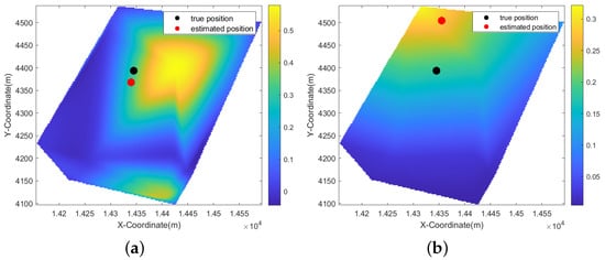
Figure 23.
The 13th ping data: (a) AI-PDA-IMM-KF result; (b) PDA-IMM-KF result. The energy values in the background of the figure represent the magnitude of the association probabilities.
The RMSE in the 14th ping data remains high with the IMM-KF algorithm in Figure 24 although the target with the highest amplitude is already very close to the true position because it is influenced by the 13th ping data and cannot be tracked in the right way. Consequently, the tracking position estimated after the 13th ping deviates significantly from the true position, leading to further tracking errors. The analysis of sea trial data validates the simulation results, while the proposed algorithm exhibits strong robustness, enabling accurate and stable tracking of maneuvering targets.

Figure 24.
The 14th ping data: (a) bearing–time–amplitude result; (b) bearing–time result.
The computational efficiency was evaluated by average processing time per ping on an Intel i5-13500HX CPU. As shown in Table 2, the IMM-KF algorithm is the most efficient at 0.09 ms/ping, benefiting from its simple structure, followed by the AI-PDA-KF algorithm (0.18 ms), the PDA-IMM-KF algorithm (0.33 ms), and the proposed AI-PDA-IMM-KF algorithm (0.47 ms). The increased cost of the AI-PDA-IMM-KF algorithm is mainly due to the IMM framework and amplitude information fusion. Despite this, the overall runtime remains well within real time constraints, making the proposed algorithm suitable for AUV-based tracking applications.
Table 2.
Average running time of different algorithms.
5. Discussion
From the simulation experiments that involve multiple targets, the amplitude information performs well when there are no complex scenarios between targets. However, once the targets converge, the amplitude information may lead to tracking errors. It can also be seen that Doppler information helps prevent tracking errors in multi-target scenarios and significantly improves tracking accuracy. The sea trial data used LFM signals, whose inherent insensitivity to Doppler shifts limited the validation of Doppler information under real ocean conditions. However, the sea trial results clearly demonstrate the core value of the multi-information-assisted framework: even under the constraint of relying solely on amplitude information, the proposed algorithm significantly outperforms traditional algorithms in tracking accuracy. This strongly validates the effectiveness of leveraging auxiliary feature information to enhance tracking performance in active sonar. The advantages of Doppler information are fully reflected in the simulation experiments, and its comprehensive validation in real-world systems will be a key focus of future work. In future work, we will conduct experiments and tests using Doppler-sensitive waveforms to make full use of Doppler information and further improve tracking performance.
6. Conclusions
This paper proposes a multi-information-assisted PDA algorithm based on the PDA framework, considering the integration of amplitude and Doppler information to address the challenges of target tracking for AUVs in shallow water. The algorithm combines different information to improve measurement association and target state estimation, enhancing the robustness of AUVs in dynamic underwater surveillance. By further integrating the IMM algorithm to adapt to diverse marine target motion patterns, the proposed algorithm demonstrates superior data association efficiency and tracking accuracy compared to traditional PDA algorithms. These advances are particularly critical for AUV-based operations. Simulation experiments of two multi-target scenarios demonstrate the effectiveness of amplitude information and Doppler information on the algorithm, and the accuracy is greatly improved. When applied to sea trial data collected from simulated AUV-deployed bistatic sonar systems, the algorithm achieves a 23.95% improvement in tracking accuracy using only amplitude information compared to traditional PDA algorithms. These results demonstrate the effectiveness and robustness of the algorithm proposed in this paper. The algorithm proposed in this paper is currently applied in shallow water. Future extensions are needed for deep water. Although the fusion of amplitude information and Doppler information can be retained, adaptations such as incorporating more appropriate acoustic propagation models and enhancing the weighting of Doppler information will be required to accommodate the physical characteristics of deep water. Currently, Doppler information utilization remains elementary. It will be more important to use Doppler information to track highly maneuverable targets, which is also the focus of our future research. Implementing these algorithms on embedded AUV processors for real-time tracking, coupled with multi-AUV collaborative sonar networks, will further advance robust underwater perception capabilities for ocean engineering.
Author Contributions
Z.B.: methodology, software, investigation, writing—original draft preparation; Y.Z.: investigation, resources, data curation, project administration, and funding acquisition; Y.T.: investigation, resources, writing—review and editing, supervision, project administration, and funding acquisition; J.W.: investigation, writing—review and editing, supervision, and funding acquisition; H.W.: investigation, conceptualization, writing—review and editing; C.L.: investigation, conceptualization, writing—review and editing; C.H.: investigation, writing—review and editing; P.Z.: investigation, writing—review and editing. All authors have read and agreed to the published version of the manuscript.
Funding
This research was funded by the National Natural Science Foundation of China (Grant No. 62301551).
Data Availability Statement
The data that support the findings of this study are available from the Institute of Acoustics of the Chinese Academy of Sciences. Restrictions apply to the availability of these data, which were used under license for this study. Data are available from the authors upon reasonable request and with the permission of the Institute of Acoustics of the Chinese Academy of Sciences.
Acknowledgments
The authors would like to thank the editors and reviewers for their comments on the manuscript of this article.
Conflicts of Interest
The authors declare no conflicts of interest.
Abbreviations
The following abbreviations are used in this manuscript:
| AUV | Autonomous underwater vehicle |
| RFS | Random finite set |
| PDA | Probabilistic data association |
| IMM | Interactive multiple model |
| RMSE | Root mean square error |
| MC | Monte Carlo |
| CV | Constant velocity |
| CT | Coordinated turn |
| AI | Amplitude information |
| MI | Multi-information |
| KF | Kalman filter |
| LFM | Linear frequency modulation |
References
- Cox, H. Fundamentals of bistatic active sonar. In Underwater Acoustic Data Processing; Springer: Berlin/Heidelberg, Germany, 1989; pp. 3–24. [Google Scholar]
- Brown, M.V.; Saenger, R.A. Bistatic Backscattering of Low-Frequency Underwater Sound from the Ocean Surface. J. Acoust. Soc. Am. 1972, 52, 944–960. [Google Scholar] [CrossRef]
- Zhang, Y.; Zhang, H.; Liu, J.; Zhang, S.; Liu, Z.; Lyu, E.; Chen, W. Submarine pipeline tracking technology based on AUVs with forward looking sonar. Appl. Ocean Res. 2022, 122, 103128. [Google Scholar] [CrossRef]
- Lokhande, S.; Malarkodi, A.; Latha, G.; Srinivasan, S. Autonomous detection, localization and tracking of ships by underwater acoustic sensing using vector sensor array. Appl. Ocean Res. 2025, 154, 104389. [Google Scholar] [CrossRef]
- Erdinc, O.; Willett, P.; Coraluppi, S. The Gaussian mixture cardinalized PHD tracker on MSTWG and SEABAR’07 datasets. In Proceedings of the 2008 11th International Conference on Information Fusion, Cologne, Germany, 30 June–3 July 2008; IEEE: New York, NY, USA, 2008; pp. 1–8. [Google Scholar]
- Willett, P.; Coraluppi, S. MLPDA and MLPMHT applied to some MSTWG data. In Proceedings of the 2006 9th International Conference on Information Fusion, Florence, Italy, 10–13 July 2006; IEEE: New York, NY, USA, 2006; pp. 1–8. [Google Scholar]
- Broetje, M.; Broetje, L.; Ehlers, F. Parameter state estimation for bistatic sonar systems. IET Radar Sonar Navig. 2018, 12, 821–832. [Google Scholar] [CrossRef]
- Kim, S.; Ku, B.; Hong, W.; Ko, H. Performance comparison of target localization for active sonar systems. IEEE Trans. Aerosp. Electron. Syst. 2008, 44, 1371–1380. [Google Scholar] [CrossRef]
- Zhang, C.; Shi, W.; Gong, Z.; Zhang, Q.; Li, C. Target tracking using time delay and Doppler shift with nonnegligible motion effect in bistatic sonar. IEEE Sens. J. 2023, 23, 15910–15923. [Google Scholar] [CrossRef]
- Ferri, G.; Munafò, A.; Goldhahn, R.; LePage, K. Results from COLLAB13 sea trial on tracking underwater targets with AUVs in bistatic sonar scenarios. In Proceedings of the 2014 Oceans-St. John’s, St. John’s, NL, Canada, 14–19 September 2014; IEEE: New York, NY, USA, 2014; pp. 1–9. [Google Scholar]
- LePage, K.D. Statistics of broad-band bottom reverberation predictions in shallow-water waveguides. IEEE J. Ocean. Eng. 2004, 29, 330–346. [Google Scholar] [CrossRef]
- Holland, C.W.; Preston, J.R.; Abraham, D.A. Long-range acoustic scattering from a shallow-water mud-volcano cluster. J. Acoust. Soc. Am. 2007, 122, 1946–1958. [Google Scholar] [CrossRef]
- Fialkowski, J.M.; Gauss, R.C.; Drumheller, D.M. Measurements and modeling of low-frequency near-surface scattering statistics. IEEE J. Ocean. Eng. 2004, 29, 197–214. [Google Scholar] [CrossRef]
- Hodges, R.P. Underwater Acoustics: Analysis, Design and Performance of Sonar; John Wiley & Sons: Hoboken, NJ, USA, 2011. [Google Scholar]
- Kumar, M.; Mondal, S. Recent developments on target tracking problems: A review. Ocean Eng. 2021, 236, 109558. [Google Scholar] [CrossRef]
- Zhang, D.; Gao, L.; Teng, T.; Jia, Z. Underwater moving target detection using track-before-detect method with low power and high refresh rate signal. Appl. Acoust. 2021, 174, 107750. [Google Scholar] [CrossRef]
- Coraluppi, S. Multistatic sonar localization. IEEE J. Ocean. Eng. 2006, 31, 964–974. [Google Scholar] [CrossRef]
- Sittler, R.W. An optimal data association problem in surveillance theory. IEEE Trans. Mil. Electron. 1964, 8, 125–139. [Google Scholar] [CrossRef]
- Singer, R.A.; Stein, J.J. An optimal tracking filter for processing sensor data of imprecisely determined origin in surveillance systems. In Proceedings of the 1971 IEEE Conference on Decision and Control, Miami Beach, FL, USA, 15–17 December 1971; IEEE: New York, NY, USA, 1971; pp. 171–175. [Google Scholar]
- Sun, J.; Liu, C.; Li, Q.; Chen, X. Labelled multi-Bernoulli filter with amplitude information for tracking marine weak targets. IET Radar Sonar Navig. 2019, 13, 983–991. [Google Scholar] [CrossRef]
- Liu, H.; Jiang, Q.; Qin, Y.; Yin, R.; Zhao, S. Double layer weighted unscented Kalman underwater target tracking algorithm based on sound speed profile. Ocean Eng. 2022, 266, 112982. [Google Scholar] [CrossRef]
- Yang, Y.; Zhang, B.; Hou, X. Robust cardinalized probability hypothesis density filter based underwater multi-target direction-of-arrival tracking with uncertain measurement noise. Appl. Acoust. 2024, 216, 109815. [Google Scholar] [CrossRef]
- Ali, W.; Li, Y.; Raja, M.A.Z.; Ahmed, N. Generalized pseudo Bayesian algorithms for tracking of multiple model underwater maneuvering target. Appl. Acoust. 2020, 166, 107345. [Google Scholar] [CrossRef]
- Lerro, D.; Bar-Shalom, Y. Automated tracking with target amplitude information. In Proceedings of the 1990 American Control Conference, San Diego, CA, USA, 23–25 May 1990; IEEE: New York, NY, USA, 1990; pp. 2875–2880. [Google Scholar]
- Lerro, D.; Bar-Shalom, Y. Interacting multiple model tracking with target amplitude feature. IEEE Trans. Aerosp. Electron. Syst. 1993, 29, 494–509. [Google Scholar] [CrossRef]
- Wang, X.; Musicki, D.; Ellem, R.; Fletcher, F. Efficient and enhanced multi-target tracking with Doppler measurements. IEEE Trans. Aerosp. Electron. Syst. 2009, 45, 1400–1417. [Google Scholar] [CrossRef]
- Mušicki, D.; Lyul Song, T.; Lee, H.H.; Nešić, D. Correlated Doppler-assisted target tracking in clutter. IET Radar Sonar Navig. 2013, 7, 94–100. [Google Scholar] [CrossRef]
- Bar-Shalom, Y. Negative correlation and optimal tracking with Doppler measurements. IEEE Trans. Aerosp. Electron. Syst. 2001, 37, 1117–1120. [Google Scholar] [CrossRef]
- Sun, X.; Li, R.; Zhou, L. Multidimensional information fusion in active sonar via the generalized labeled multi-Bernoulli filter. IEEE Access 2020, 8, 211335–211347. [Google Scholar] [CrossRef]
- Sandys-Wunsch, M.; Hazen, M.G. Multistatic localization error due to receiver positioning errors. IEEE J. Ocean. Eng. 2002, 27, 328–334. [Google Scholar] [CrossRef]
- Angelari, R.D. The ambiguity function applied to underwater acoustic signal processing: A review. Ocean Eng. 1970, 2, 13–26. [Google Scholar] [CrossRef]


Disclaimer/Publisher’s Note: The statements, opinions and data contained in all publications are solely those of the individual author(s) and contributor(s) and not of MDPI and/or the editor(s). MDPI and/or the editor(s) disclaim responsibility for any injury to people or property resulting from any ideas, methods, instructions or products referred to in the content. |
© 2025 by the authors. Licensee MDPI, Basel, Switzerland. This article is an open access article distributed under the terms and conditions of the Creative Commons Attribution (CC BY) license (https://creativecommons.org/licenses/by/4.0/).