Abstract
The passive bistatic synthetic aperture radar (PBSAR) is recognized as a critical developmental direction for future radar systems. To validate its operational feasibility, we designed a PBSAR system. However, significant measurement errors were observed to degrade imaging quality. Conventional autofocusing algorithms operate under the assumption that measurement errors primarily perturb phase components while exerting negligible influence on signal envelopes. The results from the system demonstrate the invalidity of this assumption, and the performance of conventional autofocusing algorithms severely degrades under enhanced resolution requirements. To address this limitation, we propose a frequency-domain division-based multi-stage autofocusing framework. This approach improves the frequency-dependent characterization of phase errors and incorporates an image sharpness-optimized autofocusing strategy. The estimated phase errors are directly applied for signal-level compensation, yielding refocused imagery with enhanced clarity while achieving an efficiency improvement exceeding 75%. Furthermore, we introduce a ground Cartesian back projection algorithm to adapt it to the PBSAR architecture, significantly improving computational efficiency in autofocusing processing. The integration of the proposed autofocusing algorithm with the accelerated imaging framework achieves an enhancement in autofocusing performance and a computational efficiency improvement by an order of magnitude. Simulations and experimental validations confirm that the proposed methodology exhibits marked advantages in both operational efficiency and focusing performance.
1. Introduction
Passive bistatic synthetic aperture radar (PBSAR), as a pivotal extension of conventional monostatic SAR systems, demonstrates significant advantages, including enhanced concealment capabilities, improved anti-jamming performance, and flexible system configuration [1,2,3]. While PBSAR has emerged as a promising paradigm for covert surveillance and multi-perspective scattering characterization, its practical implementation faces critical technical challenges. These challenges primarily arise because the complex bistatic geometry configuration disrupts the azimuthal invariance assumption inherent in conventional imaging algorithms; traditional frequency-domain imaging techniques become inapplicable to PBSAR. Meanwhile, the adoption of time-domain algorithms, e.g., back-projection (BP), leads to compromised computational efficiency and incompatibility with classical phase grade autofocus (PGA) methodologies in non-ideal trajectories imaging scenarios. Consequently, PBSAR necessitates sophisticated autofocusing (AF) algorithms to compensate for phase errors induced by platform trajectory uncertainties [2].
This paper presents a novel PBSAR framework utilizing geostationary orbit (GEO) satellite illuminators, with particular emphasis on addressing two critical challenges in practical implementations: the autofocusing problem arising from severe phase errors induced by system measuring error and the development of a computationally efficient imaging algorithm. We systematically investigate the spatiotemporal coupling effects in bistatic observation geometry and propose a joint optimization strategy for phase error correction and fast image formation.
The most widely used PGA algorithm is constrained in its application to PBSAR due to its inherent reliance on the Fourier transform relationship between the image and phase domains, as well as its incompatibility with time-domain BP algorithms [4,5,6,7,8,9]. In contrast, the image quality metric (IQM)-based autofocusing back-projection (AFBP) algorithm demonstrates superior flexibility and adaptability, enabling effective integration with PBSAR systems [10,11]. Nevertheless, practical implementation of the AFBP methodology still encounters significant challenges, including elevated computational complexity and performance degradation under conditions of severe measurement errors [12,13,14,15].
The conventional IQM-based AFBP algorithm initiates with a coarsely focused BP image. By leveraging IQMs, such as entropy, image sharpness, contrast, and others, AFBP formulates an optimization problem targeting phase error compensation [16,17,18,19]. Through iteration, the algorithm converges to correct phase errors induced by non-ideal trajectories, propagation inaccuracies, and analogous systematic deviations [20].
However, regardless of the specific IQM employed, conventional AFBP algorithms universally assume that the aggregate system errors affect only the phase component of echoes, with envelope distortions deemed negligible or eliminable through preprocessing [20]. Nevertheless, as signal carrier frequencies and bandwidths continue to escalate in PBSAR systems, phase error compensation has become increasingly critical. Concurrently, the miniaturization trend in imaging systems has rendered high-precision positioning systems impractical for deployment. Consequently, traditional AFBP approaches prove inadequate in addressing severe image defocusing caused by systematic errors. Phase error exhibits dual-domain degradation characteristics: time-domain envelope distortions and frequency-dependent phase aberrations.
To resolve these challenges, recent research has explored multiple directions. Ref. [21] introduced a multi-sub-band filtered BP algorithm that processes multiple sub-bands in the wavenumber domain synchronously before fusion. However, the acquisition of wavenumber spectra for PBSAR sub-images remains inherently challenging, while the necessity for joint processing of multiple sub-bands introduces substantial computational burdens. Ref. [22] developed a coarse-to-fine autofocusing strategy that progressively refines resolution to approximate true phase errors. However, the inherent implementation challenges of FBP in PBSAR and the computational inefficiency associated with repeated autofocusing operations have significantly constrained its practical adoption.
Building upon these advancements, this paper investigates a multi-stage AFBP (MSAFBP) algorithm leveraging image sharpness optimization. The proposed methodology offers three principal innovations: First, image sharpness is prioritized over other IQMs due to its inherent computational efficiency, eliminating redundant iterative computations. Second, frequency-domain partitioning techniques are employed to decompose sub-band signals, generating coarsely focused BP images that enable frequency-dependent phase error estimation. Third, unlike conventional image-domain compensation, our approach implements phase correction in the frequency domain by exploiting phase-wrapping persistence properties, achieving rapid system error compensation. Crucially, this multi-stage framework maintains compatibility with diverse IQMs and back-projection architectures, ensuring exceptional scalability and robustness. The synthesized advantages of rigorous error compensation, computational efficiency, and system adaptability position the proposed algorithm as a significant advancement in PBSAR autofocusing technology.
Building upon this foundation, to address the inefficiency caused by the limited integration of conventional AFBP frameworks, this study explores an enhanced rapid AFBP (ERAFBP) algorithm. The methodology comprises two synergistic innovations: First, a rapid BP algorithm tailored for PBSAR system characteristics is introduced. Second, the proposed MSAFBP is integrated with this accelerated BP framework to achieve systemic efficiency enhancement.
While BP algorithms are widely valued for their precision, adaptability, and imaging flexibility, their prohibitive computational overhead has hindered practical deployment. Sub-aperture (SA) division has been established as a critical strategy for enhancing BP efficiency, with researchers developing various rapid BP variants over decades. Fast Back-Projection (FBP) and Fast Factorized BP (FFBP), based on the local polar coordinate, suffer from multi-stage interpolation-induced error accumulation [23,24,25,26,27,28,29,30]. Global polar coordinate-based accelerated fast BP (AF-BP) is inherently constrained by straight-trajectory assumptions incompatible with PBSAR geometries [31]. Hybrid Coordinate rapid BP algorithms demonstrating limited PBSAR compatibility without structural adaptations [32,33]. Cartesian factorized BP (CFBP), which applies Cartesian coordinates, eliminates interpolation but imposes stringent configuration requirements, exhibiting degraded accuracy in extended apertures while sacrificing imaging plane flexibility [34]. Ground Cartesian BP (GCBP) avoids interpolation yet requires spectral correction modifications prior to PBSAR integration [35,36,37].
To overcome these limitations, this work introduces an extended GCBP (EGCBP) algorithm that preemptively compensates for PBSAR bistatic distortions prior to spectral correction, enabling accurate spectral alignment and multi-sub-image fusion [35]. Crucially, the ERAFBP’s integration of the MSAFBP with the EGCBP facilitates multi-stage phase error correction at sub-image levels, preserving the MSAFBP’s robustness while significantly accelerating the processing pipeline.
The ERAFBP framework achieves three-fold advancements:
- Enhanced error tolerance: superior performance under severe phase and envelope error conditions through coupled time-frequency domain compensation.
- Computational efficiency: 60% reduction in operations compared to conventional GCBP via optimized sub-aperture partitioning.
- System robustness: configurable compatibility with diverse IQMs and BP architectures, validated across PBSAR configurations.
This systematic integration of accelerated imaging and adaptive autofocusing establishes a new benchmark for high-efficiency, high-fidelity PBSAR processing.
This paper is organized as follows. Section 1 outlines the core contributions and methodological framework of this study. Section 2.1 develops a comprehensive signal model for PBSAR and analyzes its spectral characteristics. Section 2.2 presents the enhanced ground Cartesian back-projection algorithm, detailing its bistatic distortion compensation mechanism and spectral correction workflow. Section 2.3 integrates the proposed multi-stage autofocusing back-projection (MSAFBP) strategy with the imaging framework, providing a rigorous theoretical analysis of convergence behavior and computational complexity. Section 3 validates the algorithm’s efficacy through numerical simulations and real-world scenarios, benchmarking its performance against other methods. Section 4 provides an in-depth analysis and discussion of the proposed algorithms. Section 5 concludes with a forward-looking perspective on adaptive autofocusing architectures and their potential extensions.
2. Materials and Methods
2.1. Model
To address the signal reception challenges inherent in ultra-long-range bistatic configurations, the proposed PBSAR system employs a dual-antenna architecture with spatial separation between the reference channel and echo channel, as shown in Figure 1. This design specifically resolves two critical issues: mitigation of path loss-induced signal degradation through dedicated reference antenna optimization for direct signal acquisition and preservation of phase synchronization integrity via static deployment of both the GEO satellite and reference antenna during coherent processing intervals. The synthetic aperture formation is achieved through controlled displacement of the echo antenna mounted on terrestrial or aerial moving platforms.
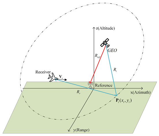
Figure 1.
Geometric configuration of the PBSAR based on the GEO satellite.
A local coordinate system is established for the PBSAR system analysis and signal modeling. As depicted in Figure 1, the origin is defined at the stationary reference antenna position . Within this framework, the position of the satellite radiation source can be derived through coordinate mapping of its orbital parameters. Similarly, the position of the receiving antenna for scene echoes is determined via the same mapping methodology.
2.1.1. Signal Model
Suppose that the signal emitted by the satellite at slow time is , where represents the envelope of the random communication signal and represents the fast time. Equation (1) gives the baseband echo expression for an arbitrary scattering center , with its coordinates is in the coordinate system in Figure 1.
In Equation (1), represents the carrier frequency, represents the bistatic time delay of the . Equation (2) gives the exact expression of , where is the speed of light, is bistatic distance delay. , and are the reference path, incident path, and reflected path, respectively.
The coordinate system configuration of the proposed PBSAR requires particular attention due to the spatially separated receiver architecture, and can be reduced to and , respectively.
The expression of the echo after range compression shown in Equation (3) indicates that the position of the main-lobe energy of the target depends on the bistatic delay. In Equation (3), denotes the reflectance of and is the signal bandwidth.
The range spectrum of the echo can be expressed in Equation (4) by the fast Fourier transform (FFT) in the fast time dimension and represents the rectangular window function.
Following the formulation of the PBSAR signal model incorporating bistatic geometry parameters, the phase error analysis reveals a critical problem. Dynamic phase errors dominated by echo antenna trajectory deviation caused by platform vibration and non-ideal motion, influencing phase terms coupled to the synthetic aperture time.
Due to the stationary characteristics of the radiation source and reference antenna, the systematic error caused by their positioning error is a time-independent constant, which is completely different from the time-coupled error in the echo antenna [35]. The phase error caused by the constant systematic error only leads to image shift and is easy to compensate for, thus it can be neglected in many analyses [25,37]. Then, the expression of bistatic slant range can be reformulated as Equation (5), where represent the ideal bistatic slant distance, and denote reflection path deviations of the echo antenna.
In Equation (5), has been reformulated as Equation (6), considering the effect of trajectory error, and denotes the 2-norm operator.
In the traditional autofocus processing, the aggregate phase error induced by all systematic measurement errors can be mathematically formulated as Equation (7), where is envelope after distance compression, and , denote the ideal delay and the actual delay including errors, respectively.
The proposed signal model achieves comprehensive formulation through generalized geometry representation with arbitrary platform trajectories, enabling efficient image processing and compensation of phase errors without prior trajectory constraints. Isolation of platform-specific errors from bistatic scattering characteristics establishes the theoretical foundation for the phase compensation strategy.
2.1.2. Analysis of the Signal Model
Both the traditional PGA algorithm and the AFBP algorithm assume that measurement errors only affect the phase of the echo without altering its envelope or, at least, are negligible. This relationship is explicitly expressed in Equation (7), where measurement errors exclusively manifest as phase perturbations in the echo signal.
However, as the carrier frequency and bandwidth of signals continue to increase, this assumption no longer holds true. Higher bandwidth demands sub-meter-level positioning accuracy, yet the combined effects of measurement errors and atmospheric disturbances make such precision unattainable. Consequently, the impact of systematic errors on the signal envelope must be explicitly accounted for, as described in Equation (8). When severe envelope distortion and misalignment occur, the main-lobe energy of target echoes will accumulate erroneously, significantly compromising the quality of two-dimensional imaging.
The range spectrum of the range-compressed signal can be expressed as Equation (9). When errors become significant enough to non-negligibly perturb the envelope, their impact on the echo manifests as frequency-dependent phase distortions from a frequency-domain perspective. Unlike the localized perturbation described in Equation (7), these distortions degrade the phase coherence across the entire effective bandwidth, thereby disrupting the critical frequency-dependent relationships essential for high-fidelity SAR imaging.
Hence, enhancing traditional autofocus methods is imperative to achieve high-quality imaging under increasingly severe phase contamination conditions. This necessitates optimizing existing algorithms to address broadband phase errors, which degrade both envelope alignment and phase coherence across the effective bandwidth.
Concurrently, the integration of autofocus processing with imaging algorithms is critically important. As previously discussed, the BP algorithm serves as a time-domain imaging method particularly suitable for PBSAR. Therefore, integrating the proposed autofocus method with BP represents a rational and evolutionary approach. Most significantly, developing rapid BP variants tailored for PBSAR and synergizing them with advanced autofocus techniques will substantially enhance adaptability to complex scenarios involving severe motion errors and phase distortions.
2.2. A Fast BP Algorithm for PBSAR Based on the GEO Satellite
2.2.1. Traditional BP Algorithm
The traditional BP algorithm is widely used in complex SAR systems due to its ability to flexibly select imaging planes, integrate with digital elevation models (DEMs) to adapt to terrain, accommodate complex bistatic configurations and arbitrary motion trajectories, and deliver precise imaging without approximations. These advantages make the BP algorithm particularly suitable for GEO-satellite-based PBSAR systems. The time-domain integral formulation of the BP algorithm is presented in Equation (10).
For an arbitrary scattering center, the computational complexity of the BP imaging result scales linearly with the total number of slow-time samples . When applied to an imaging grid of sizing (: range direction, : azimuth direction), the total computational complexity of the algorithm scales as . Its high computational complexity poses significant challenges for real-time processing.
Numerous studies have been conducted to improve the BP algorithm for enhanced computational efficiency. Most fast BP algorithms adopt an SA division approach: sub-apertures are first used to generate sub-images with coarse azimuth resolution, followed by coherent accumulation of these sub-images through interpolation or similar techniques.
GCBP stands out as one of the most applicable fast algorithms for PBSAR. While its derivation process avoids the linear trajectory assumption, it was originally developed under monostatic SAR conditions. The Cartesian coordinate system imposes stringent requirements on azimuth sampling rates, making the correction of sub-image wavenumber spectra critical.
To address this, this study builds upon GCBP by analyzing and correcting the wavenumber spectra of sub-images in GEO-satellite-based PBSAR systems. We further optimize the processing workflow and introduce a bistatic GCBP framework tailored for PBSAR, eliminating the limitations of monostatic assumption and enhancing adaptability to bistatic geometries. This advancement enables precise imaging while maintaining computational efficiency, addressing the key challenge in real-time PBSAR applications.
2.2.2. Extended Ground Cartesian Back Projection Algorithm
Similar to the accelerated BP algorithms based on the polar coordinate, the accelerated BP algorithms based on the Cartesian coordinate system also first obtain several sub-images with low azimuth resolution through sub-aperture division. The difference lies in that the polar coordinate system requires a lower sampling rate in the angular dimension, thus enabling a significant reduction in the sampling rate. In contrast, the sub-images under the Cartesian coordinate system have a wider spectral width [38]. To meet the sampling rate requirements, it is necessary to first acquire the wavenumber spectrum of the sub-images and perform compression and correction processing.
Define as representing the range wavenumber, then is the wavenumber domain expression of the echo signal. The sub-image of SA is expressed as Equation (11), where represents the coordinates of the ground Cartesian coordinate system.
The wavenumber domain expression of the is given by Equation (12), where and represent the azimuth and the range wavenumber of the SA image, respectively. denotes the slow-time duration of the SA. and represent the range and the azimuth scope of the partial imaging grid.
For the convenience of analysis, the effect of trajectory error is not considered for the time being. The derivation of the integral in Equation (12) requires the application of the principle of stationary phase (POSP), which is difficult to apply due to the relatively complex configuration of PBSAR [31]. The raw range-compressed signal are not related to or . By exchanging the integration order, the expression for the phase of the integral in Equation (12) is given in Equation (13).
By applying the POSP, the stationary-phase point is derived, as shown in Equation (14), by setting the derivative of the equation with respect to equal to zero.
It is noteworthy that the expression for is implicit, and substituting Equation (14) into Equation (12) fails to yield a valid formulation, while the issue does not exist in monostatic SAR [36]. This issue critically impedes the derivation of the wavenumber spectrum of the image.
To achieve precise wavenumber-domain alignment and recover an accurate bistatic spectrum, targeted phase compensation is imperative. Our approach prioritizes handling the and (which are distinct from those in monostatic SAR) into the bistatic time delay, enabling the signal model to converge with that of monostatic SAR. This thereby simplifies the problem of solving the fixed phase in wavenumber domain transformation, as shown in Figure 2.

Figure 2.
Schematic diagram of the process of bistatic delay term compensation.
Notably, unlike in traditional monostatic SAR, where the phase depends only on , the phase in PBSAR includes the influence of and , which is caused by the geometric configuration of PBSAR. Therefore, considering the elimination of the influence of and may make this phase consistent with that of monostatic SAR, facilitating subsequent processing.
These terms are time-decoupled (i.e., independent of slow time ). Since the wavenumber spectrum of the image is derived from the image domain, it is feasible to directly compensate for these two interference terms within the back-projection stage. The reference path remains constant throughout the processing chain and is independent of the spatial positions of the scattering centers. Consequently, its compensation can be implemented directly in the signal domain [35]. The explicit expression for the compensation factor of the reference path is provided in Equation (15).
In contrast, the incident path is spatially coupled, necessitating compensation to account for its spatial variability. Alternatively, compensation can be integrated during the back-projection process. The corresponding compensation factor is explicitly defined in Equation (16).
This compensation dynamically aligns the bistatic phase history with the monostatic framework, mitigating phase decoherence and enhancing fusion accuracy in subsequent processing stages. After compensating for the interference terms from the reference path and incident path, the phase term of the integral in Equation (13) can be simplified to Equation (17).
In the (17), the wavenumber spectrum is uniquely determined by the position of the moving receiving platform, which ensures that the solution of the fixed phase remains consistent with that in monostatic SAR [36,37]. According to the POSP, the stationary-phase point is simplified as shown in Equation (18).
According to the expression of the stationary phase in Equation (18), Equation (19) gives the integral result obtained.
Based on POSP, the integral of (17) is given in (20).
The evaluation of the integral in Equation (20) neglects constant-phase and amplitude terms, thereby simplifying the oscillatory integral to its dominant stationary phase contribution [36,37]. By introducing the phase error caused by system error, Equation (20) can be further expressed as Equation (21), and the expression explicitly isolates phase errors induced by trajectory deviations. Critically, these deviations manifest exclusively as a phase-error term in the frequency domain, leaving the wavenumber spectrum unaffected [35,37]. in Equation (21) is the error of the sub-image in the wavenumber spectrum domain. Equation (21) validates the consistency of the framework under motion perturbations.
The wavenumber-domain analysis in GEO-satellite-based PBSAR is conducted. By calibrating deviations in the wavenumber support region through geometric configuration corrections, specifically, compensating for bistatic slant-range variations and platform motion nonlinearities, the refined wavenumber support region of the sub-image is derived.
As analytically demonstrated in Equation (21), the wavenumber spectral support domain of the target exhibits a strictly linear mapping to the target’s spatial coordinates while remaining geometrically decoupled from the radar platform’s position under nominal trajectory conditions [37]. Phase errors behave in the form of the spatial-wavenumber support regions of distinct targets. When trajectory deviations are neglected, the SAR image can be reconstructed by the 2-dimensional inverse Fourier transform of Equation (21).
The bistatic geometry decouples the transmitter and receiver trajectories, necessitating a dual-path phase representation that inherently disrupts the monostatic symmetry assumed in conventional derivations. This reformulation in Equation (21) ensures phase coherence preservation while addressing the non-linear coupling of bistatic range histories, a prerequisite for accurate wavenumber-domain processing.
2.2.3. Spectral Compensation
During the derivation of Equation (21), we compensated for the effects caused by and in PBSAR, ensuring that the signal model of PBSAR aligns with that of traditional monostatic SAR. However, prior to the coherent accumulation of sub-images, compensation and correction of the wavenumber spectrum are required to eliminate the high sampling demands in the azimuth direction under the Cartesian coordinate system [36,37]. Although a denser sub-image imaging grid could circumvent this issue, the sparse sub-image imaging grid remains the core reason enabling all accelerated BP algorithms to reduce computational complexity.
While the reference and incident path-induced spectral distortions have been compensated via and , the residual perturbation from the echo path requires subsequent correction, as shown in Equation (22). In GEO-satellite-based PBSAR, the spectral centroid of the target is governed by the SA’s central time instant due to the short duration.
Following the compensation with Equation (22), the target’s wavenumber spectrum achieves centroid alignment, effectively compressing the scattering center’s spectral spread. However, the PBSAR configuration introduces nonlinear spatiotemporal evolution of the equivalent phase center. To address the spatially variant spectral inclination caused by the nonlinearity, multi-angle coherent compensation of the target’s spectrum is essential. The compensation leverages the central coordinates of the imaging grid, where azimuthal spectral broadening remains minimal. The phase compensation function for spectral inclination correction is derived as Equation (23), where is used to characterize the wavenumber support region center and the is the center of the range coordinate.
Following the four-stage spectral correction and compression framework, the Cartesian coordinate system achieves Nyquist-compliant sampling rates, thereby resolving spectral aliasing in sub-image coherent fusion. Subsequent sub-image accumulation is performed via zero-padding-based azimuth up-sampling, a computationally efficient strategy that bypasses the iterative interpolation required in conventional local polar coordinate fast BP algorithms [36].
2.2.4. Analysis of the EGCBP
The processing flow diagram of EGCBP is shown in Figure 3. Collectively, these steps form the EGCBP method, a novel extension of GCBP. EGCBP integrates a four-step spectral compression and correction cascade, dynamically refining the beam support region to accommodate spatially variant bistatic geometries while maintaining imaging fidelity.
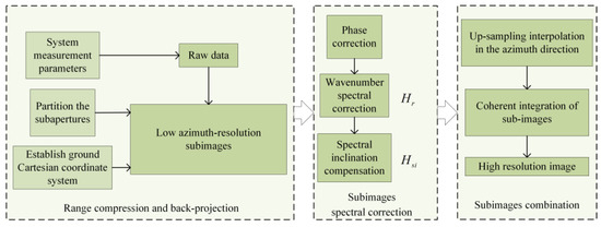
Figure 3.
Schematic diagram of the processing flow of EGCBP.
Within the ground Cartesian coordinate framework, the 2-D spectral representation of the SA image consists of a linear component dependent on spatial coordinates and a residual phase error term. Crucially, the spectral bandwidth of the imaging result aligns precisely with the wavenumber domain coverage generated during the imaging process, thereby establishing GCBP as a wavenumber spectral reconstruction algorithm. Notably, the derivation of GCBP imposes no constraints on predefined platform trajectories or SA lengths. The design of non-preset trajectory renders the algorithm inherently adaptable to diverse and complex SAR configurations while maintaining rigorous spectral fidelity.
EGCBP is well suited for PBSAR and significantly enhances operational efficiency. This section examines its computational workload. Assume the fast-time sampling points are , the slow-time data are divided into SAs, each containing slow-time samples. The fast-time upsampling factor is denoted as .
The computational complexity in the back projection stage is primarily influenced by the number of grids and SAs, as shown in (24).
In addition, all the algorithms of BP families need to perform range compression and range up-sampling, which will produce the computation burden expressed by and . Considering all the operations, the final computational complexity analysis diagram is shown in Figure 4.
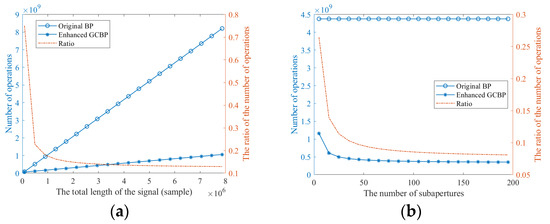
Figure 4.
Computational complexity analysis of the EGCBP algorithm. (a) Relationship between computational complexity and total signal length. (b) Relationship between the computational complexity and the number of SAs.
Figure 4a demonstrates the processing load versus total signal length under fixed parameters (10 SAs, constant fast-time length). Both EGCBP and conventional BP exhibit linear growth in computational load with increasing slow-time samples and signal length. However, EGCBP achieves about an order-of-magnitude reduction in computational complexity compared to traditional BP. Figure 4b further evaluates the load versus SA count under fixed parameters. While traditional BP stays stable, EGCBP’s load decreases asymptotically with SA count, stabilizing at large SA numbers. Both methods share the same preprocessing steps (range compression and interpolation), resulting in comparable baseline complexity. Consequently, the complexity ratio of EGCBP converges to a stable asymptote, validating EGCBP’s computational efficiency.
In summary, this section analyzes the EGCBP algorithm optimized for GEO-satellite-based PBSAR through key bistatic phase history corrections and spectral compression. The EGCBP algorithm reduces computational complexity relative to traditional BP, enabling real-time PBSAR processing. Its scalability provides a theoretical basis for the subsequent integration of the enhanced autofocus algorithm with the accelerated processing framework.
2.3. Enhanced Rapid Autofocus Algorithm
This part proposes an enhanced rapid autofocus algorithm in order to solve two problems. The first is the degradation of estimation performance in conventional AFBP for severe phase errors; we propose a multi-stage AFBP, called MSAFBP, to overcome the drawback. Then it is the combination of the proposed MSAFBP with the accelerated BP algorithm; the phase estimation process can benefit from the superior performance of MSAFBP and the high efficiency of EGCBP.
The MSAFBP algorithm addresses severe measurement errors through a frequency-domain partitioning strategy that approximates the phase error distribution. The principle and processing method of traditional AFBP will be introduced at first to provide a theoretical basis for the proposal of MSAFBP. The synergistic implementation of the proposed autofocus framework with fast BP algorithms will be analyzed in the subsequent section.
The processing flow of the conventional IQM-based AFBP algorithms is illustrated in Figure 5. The IQM-based AFBP is used to improve focusing quality by optimizing a metric reflecting the image focusing level. Starting from a phase-corrupted, defocused SAR image, the algorithm iteratively estimates and compensates spatially variant phase errors through the following steps. For each slow-time signal, the back-projected signal corresponding to the ideal phase response is subtracted from the raw image, isolating the residual phase error. The isolated residual phase error is optimized using the IQM by solving an optimization problem shown in Equation (25), where denotes the selected IQM. is the phase compensation coefficient of slow-time, and its optimal estimate under the IQM is obtained by searching .

Figure 5.
The processing flow of the traditional IQM-based AFBP algorithms. Solid arrows denote the imaging workflow, while dashed arrows indicate the autofocus processing flow.
The estimated phase error is applied to correct the slow-time signal phase, followed by coherent integration to update the SAR image. The process iterates cyclically across all azimuth signals using a coordinate descent strategy to decouple interdependencies between phase errors. Multiple global iterations are executed until the predefined IQM converges to a predetermined threshold or tends to be stable [14]. This framework enables robust compensation of both high-order phase errors, critical for preserving azimuth resolution in SAR systems.
2.3.1. Phase Optimization by Sharpness
Ash proposed a non-parametric AFBP framework leveraging image sharpness metrics [11]. This method derives slow-time-dependent phase errors by solving a constrained optimization problem formulated through the sharpness IQM, as mathematically represented in Equation (26), where the is the sharpness IQM. represents the image intensity and complex amplitude of the echo corresponding to pixel at the slow time.
The generalized sharpness metric, parameterized by , quantifies image focus quality through the relationship where image intensity depends on the phase error vector. As demonstrated by Fienup and Miller [39], the exponent governs scene-specific optimization: larger values () prioritize enhancing bright scatterers by disproportionately weighting high-intensity pixels, while smaller values () emphasize noise suppression in low-intensity regions. The classic configuration maintains balanced weighting across all pixels, serving as a general-purpose metric for scenes without pronounced intensity extremes. The classic sharpness setting will be applied in this paper. Maximizing the sharpness through phase error compensation thus adaptively optimizes focus quality based on scene characteristics.
The AFBP algorithm based on sharpness fundamentally differs from those utilizing other IQMs such as entropy or contrast. Its most distinctive feature lies in its closed-form geometric derivation to solve phase error equations, thereby eliminating iterative optimization loops. According to the mathematical deduction and geometric interpretation in [11], the optimal estimation of the phase can be obtained by solving a quartic polynomial. This deterministic, open-loop processing architecture achieves a computational efficiency gain compared to conventional iterative AFBP methods, making it particularly advantageous for real-time SAR applications requiring rapid phase error correction.
2.3.2. Multi-Stage Autofocusing Back-Projection Algorithm
The sharpness-based AFBP algorithm still faces critical challenges. While it optimizes the iterative process, it remains confined within the traditional IQM-based AFBP framework. Specifically, it fails to address the restrictive assumption that systematic errors only perturb the signal phase. Consistent with the preceding evaluation, severe systematic measurement errors induce frequency-dependent envelope distortions, rendering direct AFBP application ineffective under such conditions. Consequently, developing a novel autofocus framework capable of jointly compensating of severe phase and envelope distortions while maintaining compatibility with rapid BP implementations is paramount for advancing high-resolution SAR in error-prone environments.
To mitigate the severe degradation caused by measurement errors in SAR imaging, this paper proposes a multi-stage autofocus processing strategy. The core innovation lies in frequency-domain partitioning with controlled range-resolution degradation, enabling phase error estimation within subdivided sub-band images.
The conventional AFBP inherently relaxes the frequency-dependent characteristics of phase errors to their impact on the center frequency and directly applies this approximation across the entire bandwidth. This approach essentially treats the signal as narrowband. To address more severe phase errors, we propose a sub-band division framework in the frequency domain. By dividing the signal into multiple sub-bands via filtering techniques. The frequency-dependent characteristics of phase errors can be effectively disregarded when the number of sub-bands is sufficiently large, as demonstrated in Equation (28), where the subscript denotes the index of the sub-bands.
The full bandwidth is partitioned into sub-bands, each with a reduced bandwidth , degrading range resolution to isolate phase errors. For a sub-band, phase errors are estimated via sharpness maximization under the narrowband assumption, formulated as Equation (29), where is the image intensity of the sub-band image.
This strategy transforms the original ill-posed full-bandwidth optimization into a tractable degraded-resolution problem, effectively addressing the frequency-dependent envelope distortions. The core idea of the algorithm is shown in Figure 6. Due to the reduction in the bandwidth of the sub-band, the range resolution degrades, which limits the originally severe error within a single range cell.

Figure 6.
Schematic diagram of the frequency domain partitioning strategy.
Conventional multi-sub-band processing strategies typically realize the stepwise approximation of phase errors via multi-stage bandwidth scaling [22]. However, the sensitivity of FFT to phase discontinuities often induces range defocusing of scatterer energy due to misaligned phase histories across sub-bands. Additionally, performing phase estimation in multiple sub-bands compromises the convergence efficiency of the algorithm.
It is noted that the phase estimated through image sharpness metrics exhibits a direct correspondence with the slant-range error in signal wavelength level, as analytically formulated in Equation (30), where denotes the compensation factor corresponding to the .
It should be noted that while the frequency-domain division approach smooths the weighting of spectral components, the estimated phase errors remain accurate. Generally, when the estimation accuracy of phase errors is less than , their impact on imaging results becomes negligible. Thus, although the estimation of the phase error is based on the deteriorated resolution and envelope error, the resulting phase estimate can still be guaranteed to be wavelength-level accurate. Based on the relationship between phase errors and slant-range errors (as derived in Equation (30)), we reconstruct the phase compensation factor as formulated in Equation (31).
It is critical to emphasize that the conversion from phase errors to slant-range errors inherently suffers from phase-wrapping ambiguities. However, in the range frequency domain, both envelope errors and phase errors manifest as phase terms. By reconstructing the frequency components of the broadband signal, the slant-range error can be directly substituted into Equation (32) for compensation, since the compensation factor itself exists in a wrapped phase form. This compensation strategy at the signal level is different from the traditional AFBP updating in the image domain, and this multi-stage re-imaging allows the signal itself to directly benefit from the convergence of the phase error.
Phase errors are initially estimated from low-resolution sub-band images using sharpness maximization. The estimated phase errors are applied directly to the original wideband signal spectrum compensation. This direct compensation approach for raw broadband signals eliminates the need for iterative optimization while theoretically reducing phase errors to a negligible level, as validated by the analytical relationship between phase and slant-range errors derived in Equation (28). Direct spectral compensation avoids FFT-induced phase discontinuities to ensure preserved signal fidelity. More importantly, this strategy allows us to avoid phase estimation for multiple sub-bands, since the estimation accuracy of one sub-band is sufficient. In general, the sub-band signal can be obtained by low-pass filtering without strict sub-band division.
Once the phase errors corresponding to all slow-time signals are correctly compensated, the subsequent BP imaging process will yield a precisely refocused image, as governed by the phase-to-slant-range error relationship and validated through the IQM evaluation again.
The schematic diagram of the proposed method is shown in Figure 7. Unlike the conventional AFBP algorithm in Figure 5, which operates as a post-processing step to the BP algorithm, MSAFBP follows a multi-stage workflow: coarse imaging, phase estimation and compensation, and image reconstruction; thus, the signal-level phase compensation ensures high accuracy.
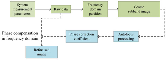
Figure 7.
Schematic of the proposed MSAFBP algorithm. Solid arrows denote the imaging workflow, while dashed arrows indicate the autofocus processing flow.
As previously analyzed, from the frequency-domain perspective, the MSAFBP method mitigates the frequency-dependent characteristics of phase errors through sub-band division. In the time domain, the controlled reduction in resolution ensures that envelope errors do not span multiple range cells. This guarantees that the energy of scattering centers remains concentrated within a single range channel, thereby preventing energy leakage and error accumulation. It is worth noting that MSAFBP does not impose restrictions on the bandwidth of sub-bands. However, in practical applications, excessive reduction in bandwidth will lead to loss of the target’s main lobe information. Therefore, the selection of sub-band bandwidth should be based on practical conditions, following the principle that measurement errors do not exceed the degraded range cells, rather than causing excessive degradation of the range resolution.
In addition to the aforementioned advantages, the proposed method inherently reduces computational complexity and memory consumption. This stems from its foundation as a time-domain phase error estimation approach, where the computational load of the IQM in the time domain is directly proportional to the number of pixels in the discrete imaging grid. By employing the frequency domain partition strategy in the frequency domain, a sparser imaging grid becomes feasible, theoretically reducing IQM computations by a factor of .
The MSAFBP algorithm has been thoroughly derived and analyzed. The proposed MSAFBP effectively addresses severe phase error contamination, a critical challenge unresolved by conventional AFBP, while concurrently reducing computational complexity. The extended applications of the proposed algorithm will be detailed subsequently.
2.3.3. Enhanced Rapid Autofocus Back-Projection Algorithm in PBSAR
While the EGCBP and MSAFBP have been validated through prior discussions, the processing framework of MSAFBP remains constrained by the conventional BP algorithmic workflow, limiting autofocus efficiency. To address this, we explore a fast autofocus algorithm tailored for GEO-satellite-based PBSAR systems. This section presents the development of the ERAFBP algorithm that retains the dual advantages of mitigating severe phase errors and maintaining computational efficiency.
The conventional AFBP methodology typically initializes phase error estimation using a coarsely focused reference image. This operational paradigm introduces inherent complexities when integrating with conventional BP algorithms, thereby constraining overall computational efficiency.
Within the EGCBP framework, precise spectral rectification of the wavenumber domain prior to sub-image fusion constitutes a critical prerequisite. This necessity arises because residual phase errors induced by slant-range miscalibrations fundamentally perturb both the spatial localization and geometric configuration of the wavenumber spectrum’s support region. Consequently, a theoretically rigorous strategy involves performing localized phase error estimation directly within the sub-image domain, where error characteristics maintain intrinsic alignment with the bistatic geometry. This will not only ensure the coherence between sub-images but also make the autofocus processing benefit from the fast-processing framework of EGCBP.
Therefore, we consider an autofocusing strategy that implements MSAFBP at the sub-image stage. This strategy maintains the ability of MSAFBP to compensate for severe phase errors. At the same time, the algorithm can also reduce the computational complexity by using the sparse imaging grid in the sub-image. Finally, with the fast-processing framework of EGCBP, the speed of the whole processing flow can be accelerated. The processing flow of the proposed ERAFBP method is shown in Figure 8.

Figure 8.
Flowchart of the proposed ERAFBP algorithm. Solid arrows denote the imaging workflow, while dashed arrows indicate the autofocus processing flow.
The integration of the proposed MSAFBP and EGCBP theoretically achieves significant computational complexity reduction while maintaining robust correction of severe phase errors. This efficiency gain is primarily attributed to the optimized processing framework of EGCBP, reduced image memory footprint and computational burden, and enhanced parallelization potential. All critical advancements over conventional BP algorithms. Specifically, grid sparsity of EGCBP minimizes redundant computations, while the analytical phase error model of MSAFBP ensures high-fidelity compensation without iterative refinement.
2.3.4. Analysis of the Proposed Autofocusing Algorithms
This section provides a comprehensive analysis of the proposed enhanced fast AFBP algorithm. While prior discussions have validated the autofocus performance, emphasis is now placed on computational efficiency, which is a key metric for practical deployment in large-scale bistatic SAR systems.
First, the proposed ERAFBP algorithm exhibits inherent compatibility with accelerated BP algorithms without compromising its inherent phase error correction capabilities. This algorithmic flexibility allows ERAFBP to be seamlessly integrated with advanced imaging methodologies while maintaining robust compensation for severe phase errors as MSAFBP.
Second, as discussed in prior analyses, the proposed autofocus strategy not only delivers superior phase error compensation but also achieves enhanced computational efficiency through reduced pixel dimensionality. When integrated with the EGCBP, the synergistic framework further reduces the image memory footprint by a factor of based on times reduction. This dual-dimensional reduction substantially alleviates the computational burden and memory overhead during autofocus processing. Critically, the inherent independence among sub-apertures enables parallel processing of sub-images when supported by hardware-level parallelism, e.g., a graphics processing unit, thereby accelerating throughput without compromising phase error correction fidelity. Notably, although the algorithm processes sub-image datasets, the slow-time signal length per sub-aperture is proportionally reduced by -fold due to sub-aperture division. Consequently, the total number of phase error estimation and compensation operations remains invariant. In summary, the proposed methodology achieves a synergistic balance between computational load reduction and parallelizability, yielding a net efficiency gain that scales optimally with both sub-band and sub-aperture parameters. This framework represents a significant advancement for high-resolution bistatic SAR systems requiring real-time autofocus under stringent phase error conditions.
In summary, the MSAFBP framework is proposed in this section, leveraging frequency-domain division and phase-error modeling to mitigate severe phase distortions. ERAFBP achieves a dual enhancement in both computational efficiency and compensation performance by integrating MSAFBP with the accelerated BP algorithm. The synergistic integration of these methodologies achieves superior imaging performance and enhanced computational efficiency. This dual advancement establishes a robust foundation for high-resolution bistatic SAR systems requiring real-time processing.
3. Results
The proposed MSAFBP and ERAFBP algorithms were validated through simulation and real-environment experiments, with their performance and efficiency quantitatively analyzed in this section. MATLAB (version R2021b) is used for all simulation experiments and data processing.
3.1. Simulation Experiments
The configuration of scattering centers in the simulation experiments, based on the coordinate system established in Figure 1, is illustrated in Figure 9.
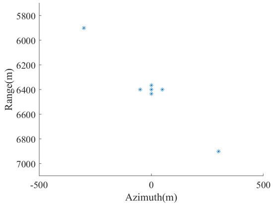
Figure 9.
Location and distribution of scattering centers in simulation experiments (including EGCBP, MSAFBP, and ERAFBP).
Based on the random characteristics of the opportunistic illuminator signal, generated pseudo-random signals are used to simulate the reference signal and echo signal. The operational parameters of selected satellites and corresponding signals are tabulated in Table 1. The sampling rate of the signal remains consistent with the signal bandwidth.

Table 1.
Parameter setting of simulation experiments.
The receiving antenna traverses along an east-west trajectory with its beam direction oriented toward the southern target imaging area. The effective synthetic aperture length measures approximately 6 m. The acquisition parameters comprise 200 slow-time samples and 2000 fast-time sampling points, corresponding to a signal duration of 0.1ms. The number of sub-apertures is configured as four to optimize the trade-off between computational efficiency and the rendering quality of sub-images.
A rigorous quantitative framework was implemented to assess the performance and computational efficiency of the proposed algorithms. Imaging contrast serves as a key metric for evaluating reconstruction quality and autofocusing precision, while algorithmic efficiency is quantified through processing time measurements.
The imaging results of the original BP algorithm are depicted in Figure 10a–e. Except for the contour plots in the rightmost column, which employed a −30 dB threshold to enhance image clarity, no additional thresholding or artificial noise was introduced to the remaining images to preserve the integrity of data visualization. Unless otherwise specified, all the subsequent experimental imaging results will adhere to this standardized protocol.
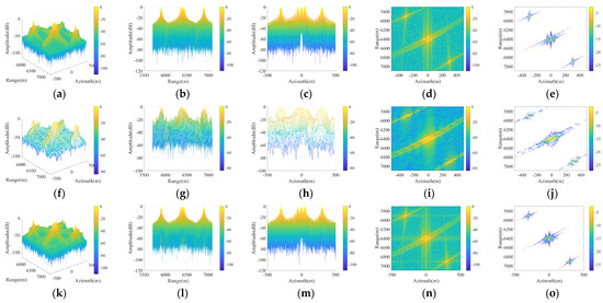
Figure 10.
Imaging results (without phase errors). (a–e) Imaging results achieved by original BP; (f–j) Sub-image results achieved by EGCBP; (k–o) Imaging results achieved by EGCBP.
For more precise quantitative analysis of simulation results, Table 2 provides key measured parameters: envelope contrast and computation time. All simulation-derived parameters were statistically averaged across 16 independent trials to ensure robust confidence intervals, which is also used for subsequent statistics.
Table 2.
The measured parameters of the simulation experiments for EGCBP.
As observed in Figure 10f–j, the azimuth resolution undergoes degradation due to the partitioning of the effective aperture, which arises from the reduction in the length of the effective synthetic aperture of the sub-aperture. Figure 10k–o demonstrate that the EGCBP reconstruction achieves imaging fidelity comparable to the theoretical limit of conventional BP, which corresponds to the contrast in Table 2. Scattering centers within the central region validate the preserved resolving capability of the EGCBP framework, whereas peripheral scatterers illustrate its robust imaging performance in off-center areas. Furthermore, as evidenced by the computation time in Table 2, the sub-aperture division strategy significantly enhances processing efficiency.
Furthermore, simulation experiments are conducted to verify the performance and efficiency of MSAFBP. During the experiments, the original signal was filtered to generate a sub-band signal with a bandwidth of 1/8 of the original, which was then used to implement autofocus processing. The performance validation of MSAFBP is demonstrated in Figure 11 where systematic errors are configured as random motion deviations. And the measured parameters are detailed in Table 3.
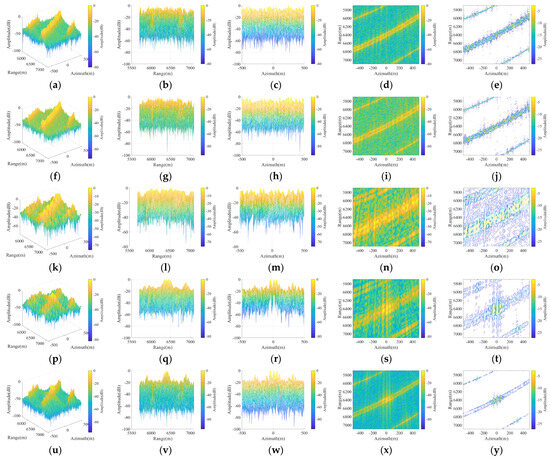
Figure 11.
The results of the MSAFBP algorithm. (a–e) Imaging results achieved by original BP; (f–j) Autofocusing results achieved by sharpness-based AFBP; (k–o) Sub-band image results achieved by BP; (p–t) Sub-band image autofocusing results achieved by MSAFBP; (u–y) Autofocusing results achieved by MSAFBP.
Table 3.
The measured parameters of the simulation experiments for MSAFBP.
The errors critically disrupt phase continuity and corrupt the envelope structure of radar echoes. The original imaging results in Figure 11a–e and the AFBP outcomes in Figure 11f–j reveal both the pronounced impact of such disturbances and the severe performance degradation inherent to conventional AFBP algorithms. As evidenced by the contrast metrics in Table 3, the sharpness-based AFBP achieves only marginal contrast enhancement. Consequently, the results in Figure 11f–j exhibit poorly resolved scattering centers, which is attributed to residual defocusing artifacts and significant energy leakage.
In contrast to the sub-band imageries in Figure 11k–o,p–t, achieved by the autofocus-processed results based on frequency partitioning strategies, they exhibit effective mitigation of frequency-dependent errors and enhanced focusing precision. The sharpness-based autofocusing process increased the image contrast from 1.5276 to 1.8775 in the sub-band images (Sub-band image (sharpness) in Table 3) compared to their defocused counterparts (Sub-band image (unfocused) in Table 3) without autofocusing. The final MSAFBP reconstruction in Figure 11u–y demonstrates superior refocusing through phase error estimation derived from sub-band data, yielding imaging fidelity that closely approximates the theoretical benchmarks of the original BP results in Figure 10. This is consistent with the improvement in contrast of the reconstructed BP images in Table 3, where the metric increased from 2.3169 before autofocusing (BP (unfocused) in Table 3) to 3.1142 post-processing (BP (reconstructed) in Table 3). Furthermore, the total processing time of the proposed MSAFBP is merely 24.8% of that required by conventional AFBP algorithms, as shown in Table 3, highlighting its substantial efficiency gains.
It is critical to note that variations in imaging settings caused significant disparities in contrast metrics across different types of images; thus, contrast comparisons are meaningful only between images within the same category. The rationale equally applies to subsequent analyses of sub-images and sub-band sub-images.
Expanding the analysis, simulation experiments of the ERAFBP algorithm were conducted. Figure 12 presents defocused images for comparative analysis. The defocused image obtained from conventional BP (shown in Figure 11a–e is not redundantly displayed here. Compared to the ideal imaging results in Figure 10, the defocused images in Figure 12a–j exhibit severe energy leakage and poorly resolved scattering centers, a degradation further corroborated by the lower contrast metrics of BP (unfocused), EGCBP (unfocused), and Sub-image (unfocused) in Table 4. Figure 12k–o presents the sub-band sub-images obtained through sub-aperture division followed by frequency partitioning. These sub-band sub-images also exhibit ineffective energy accumulation, particularly under severe system errors, resulting in unresolved scattering centers and degraded imaging fidelity.
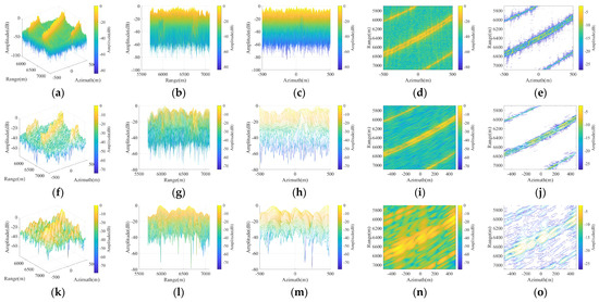
Figure 12.
Unfocused results with severe systematic errors. (a–e) Unfocused imaging results achieved by original EGCBP; (f–j) Unfocused sub-image results achieved by EGCBP; (k–o) Unfocused sub-band sub-image results achieved by EGCBP.
Table 4.
The measured parameters of the simulation experiments.
To address this, the autofocus strategy from MSAFBP was employed during the sub-image processing stage for phase error estimation. The proposed method generates the refocused sub-band sub-images shown in Figure 13a–e. Compared to their defocused counterparts in Figure 12k–o, the MSAFBP-processed images demonstrate a contrast improvement from 1.4235 to 1.7412, as validated by the metrics in Table 4. Similarly, the reconstructed sub-images in Figure 13f–j exhibit enhanced focusing performance, aligning with the quantitative contrast metrics (from 1.6958 to 1.9325) in Table 4. Ultimately, through the multi-image fusion, the proposed ERAFBP achieves the final imaging results shown in Figure 13k–o, which exhibit significant focusing enhancement compared to those in Figure 12a–e. The proposed ERAFBP achieves a contrast improvement from 2.3221 to 3.0215 in Table 4, outperforming the 2.4120 value of conventional AFBP. As evidenced, scattering centers exhibit enhanced energy concentration in the ERAFBP output (refer to the 3.3621 of imaging results achieved by BP in Figure 10), demonstrating closer alignment with theoretical benchmarks. The minor degradation, in contrast, arises from slight residual phase errors that persist in the autofocus procedure and interpolation errors introduced during the sub-image processing stage.
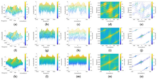
Figure 13.
The imaging results of the ERAFBP. (a–e) Sub-band sub-image autofocusing results achieved by ERAFBP; (f–j) Sub-image autofocusing results achieved by ERAFBP; (k–o) Autofocusing results achieved by ERAFBP.
Quantitative analysis of imaging contrast in Table 4 reveals that ERAFBP further enhances computational efficiency over MSAFBP (from 4.9890 in Table 3 to 2.0254 in Table 4) while preserving its robust autofocusing performance. Under the simulated parameter configuration, ERAFBP achieves a processing time of merely 10.1% of that required by the conventional AFBP algorithm.
Notably, while the proposed autofocus strategy necessitates multi-stage processing and secondary back-projection, computation time statistics in Table 4 demonstrate that the computational overhead of back-projection remains substantially lower than that of autofocus optimization. Consequently, the efficiency gains in the autofocus phase fully compensate for the added projection burden, preserving the overall computational advantage over conventional methods.
In conclusion, compared to motion-error-corrupted BP imagery, conventional AFBP demonstrates limited quality enhancement, whereas the developed MSAFBP framework demonstrates robust capability in handling autofocus processing under challenging systematic error conditions while simultaneously improving computational efficiency. By synergistically integrating MSAFBP with the proposed EGCBP, the ERAFBP algorithm establishes an optimized rapid autofocus architecture that significantly enhances the operational efficiency of autofocus methodologies.
3.2. Experiments in Real Environment
For real-environment validation, a customized data reception and processing system was designed to acquire and process experimental data. The receiving system operates in the Ku band and is equipped with a multi-channel high-speed sampling system, which is shared by the reference antenna and echo antenna. The received signal will be down converted to baseband and sampled for further processing. A circularly polarized high-gain parabolic antenna (Figure 14a) was deployed to acquire reference signals from a GEO satellite positioned at 92.2°E. This satellite achieves stable regional coverage by retransmitting broadcast television signals. The signal modulation format is a phase-modulated signal, encompassing multiple channels. The horn antenna configuration shown in Figure 14b generated effective aperture synthesis for achieving high azimuthal resolution through controlled platform displacement. Due to the small platform of the echo antenna, it cannot be equipped with a high-precision positioning device during the movement. The reference antenna, on the contrary, has a high-precision positioning system and remains stationary during data acquisition.
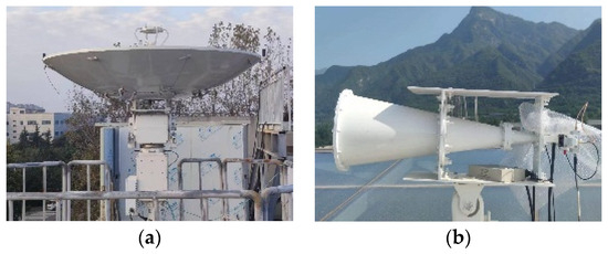
Figure 14.
Experimental system. (a) Reference antenna; (b) Echo antenna.
The experimental setup aligns with the coordinate system defined in Figure 1. The echo antenna traverses an east-west trajectory with its beam oriented northward, achieving an effective synthetic aperture length of approximately 10 m. The operating bandwidth of the system is 100 MHz, which is slightly larger than the effective bandwidth of the signal. A small vehicle containing potential strong scattering points was present within the scene, which can be used to validate the system’s imaging capabilities.
Figure 15 presents the imaging results of the original BP algorithm and those proposed algorithms in this study, including the intermediate steps. Due to the strong noise effect in the real environment, the threshold of the contour map was adjusted to −20 dB. The imaging results achieved by BP without AF processing, as shown in Figure 15a–c, are suboptimal for unpredictable deviations in the motion trajectory. The MSAFBP autofocusing strategy proposed in this paper demonstrates superior performance over the conventional AFBP algorithm in Figure 15d–f, producing clearer and better-focused images that correspond to real-environment structures, as shown in Figure 15g–i. As evidenced by the quantitative parameter measurements presented in Table 5, MSAFBP used less time (15.396541 s) to increase the contrast to 1.3035. In contrast, AFBP took 64.038574 s but only increased the contrast from 1.2211 (the original BP result) to 1.2603. Thus, MSAFBP exhibits enhanced focusing capability while maintaining higher computational efficiency. Similarly, the imaging results of the proposed ERAFBP in Figure 15m–o demonstrate improved focusing performance compared to results of EGCBP in Figure 15j–l.
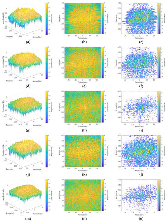
Figure 15.
Real-environment experimental results. (a–c) Imaging results achieved by BP; (d–f) Imaging results achieved by AFBP; (g–i) Imaging results achieved by MSAFBP; (j–l) Imaging results achieved by EGCBP; (m–o) Imaging results achieved by ERAFBP.
Table 5.
Measured Parameters of real-environment experimental results.
Through implementation of an accelerated sub-aperture division strategy, the EGCBP algorithm achieves significant operational speed improvements while maintaining high autofocus performance, a conclusion substantiated by the measurement parameters in Table 5. It should be noted that, consistent with the conclusions of the simulation experiments, ERAFBP has inferior focusing performance compared to MSAFBP (1.2915 vs. 1.3035) due to sub-image interpolation, which is an inherent issue in sub-image fusion. However, it has higher efficiency, achieving a shorter computation time of 3.519445 s. Therefore, in practical scenarios, it is crucial to select and apply algorithms based on actual needs to achieve a balance between efficiency and performance.
These experimental results from practical environmental testing validate both the performance efficacy and operational efficiency of our proposed algorithms, showing consistent alignment with findings from simulation experiments.
4. Discussion
The proposed algorithms have undergone rigorous theoretical validation, with their performance and efficiency further verified through both simulation experiments and real-world testing. This section provides an in-depth discussion of the algorithms, focusing on four key aspects: computational efficiency, imaging and autofocusing performance, scalability, and potential future research directions.
In terms of computational efficiency, both EGCBP and MSAFBP demonstrate significant advantages over conventional algorithms. Although they are applied to fast imaging and autofocusing processing, respectively, their efficiency gains originate from reduced imaging grid density in sub-images. Specifically, EGCBP employs a sub-aperture division strategy to decrease the azimuth resolution of sub-images, thereby reducing the azimuthal imaging grid density by a factor of . This is validated by the data in Figure 10 and Table 4. MSAFBP reduces the sampling density in the fast-time and range dimensions via frequency-domain signal partitioning. The reduction ratio is proportional to (the ratio of the sub-band bandwidth to the total bandwidth), as shown in Table 3. Notably, while MSAFBP requires sub-image reconstruction, introducing redundant operations compared to traditional AFBP, the computational time for image reconstruction remains negligible relative to autofocusing processing (see Table 3). Thus, MSAFBP retains an overall efficiency advantage due to its superior efficiency in autofocus processing. Finally, the proposed ERAFBP synergistically combines the dual-dimensional grid density reduction in EGCBP and MSAFBP: azimuth density reduction by . and range density reduction by . This integration elevates ERAFBP’s computational efficiency to a higher level, making it suitable for imaging systems with stringent real-time requirements.
In terms of performance and accuracy, both EGCBP and MSAFBP exhibit robust results. Compared to accelerated BP algorithms using polar or hybrid coordinate systems, EGCBP eliminates the need for point-wise interpolation during sub-image accumulation. The frequency-domain zero-padding strategy is operationally efficient, extra-error-free, and applicable to PBSAR. These advantages ensure superior theoretical accuracy, as validated by the simulation results in Figure 10. The autofocusing process of MSAFBP preserves the intrinsic form of phase errors, ensuring phase compensation accuracy equivalent to traditional AFBP. Both are non-parametric and capable of handling high-order phase errors. Unlike traditional AFBP, MSAFBP can address severe phase error contamination through an improved frequency-domain sub-band partitioning strategy. Meanwhile, frequency-domain signal-level phase compensation is also more precise than the image-domain compensation of traditional AFBP. Of course, the selection of sub-band bandwidth needs to be flexibly analyzed based on actual conditions, and it is advisable to use the system measurement error being less than the degraded range resolution as the criterion. MSAFBP enhances robustness against severe system measurement errors, as evidenced by the results in Figure 11 and Figure 15. By inheriting the merits of EGCBP and MSAFBP, ERAFBP maintains higher efficiency than conventional algorithms while achieving enhanced compensation capabilities. This synergy positions it as a high-precision solution for complex imaging scenarios.
Beyond these advantages, the proposed ERAFBP demonstrates exceptional robustness and scalability across diverse SAR configurations. Initially, while EGCBP is specifically designed for PBSAR based on the GEO satellite, ERAFBP remains untrammeled to the choice of accelerated BP methods, exhibiting compatibility with accelerated BP algorithms selected based on system-specific requirements. Even in scenarios with relaxed real-time constraints, ERAFBP can integrate with conventional BP, simplified to MSAFBP. Furthermore, although the non-iterative sharpness-based AFBP framework was prioritized due to its computational efficiency in this paper, MSAFBP and ERAFBP are not inherently bound to specific IQMs. They can seamlessly adapt to alternative IQMs (e.g., entropy, contrast) to meet specialized operational needs. Meanwhile, the proposed framework remains adaptable to integration with more refined autofocus strategies, such as image segmentation or block-wise processing to solve the problem of phase error spatial variability. This compatibility ensures robust compensation for different situations without sacrificing efficiency and accuracy. Thus, the framework provides a versatile and extensible foundation for autofocus-enhanced BP processing.
Collectively, ERAFBP’s system-agnostic design and modular integration capabilities allow reconfiguration to combine various accelerated BP algorithms and IQMs, thereby ensuring adaptability to emerging challenges in evolving SAR. This versatility is indicated in Figure 16, where the proposed algorithms can be combined with the generalized accelerated BP algorithms and arbitrary IQMs.
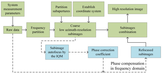
Figure 16.
Discussion on the proposed ERAFBP algorithm. Solid arrows denote the imaging work-flow, while dashed arrows indicate the autofocus processing flow.
The application of the proposed algorithm in PBSAR is pivotal for advancing its development, and exploring generalized fast imaging algorithms and autofocusing algorithms remains equally critical. While EGCBP demonstrates adaptability to single-stationary bistatic SAR, extending it to generalized bistatic SAR configurations represents a vital future research direction. The proposed autofocusing algorithm addresses two key limitations of conventional AFBP: low efficiency and diminished capability in handling severe system errors. However, resolving another inherent assumption in AFBP, the absence of spatial variability in phase errors, remains an urgent and significant challenge for further investigation.
5. Conclusions
To address the computational inefficiency of conventional AFBP algorithms and their limited robustness under severe system errors. This paper proposes a novel algorithm, MSAFBP, based on a frequency division strategy. Frequency partitioning enables MSAFBP to mitigate the frequency-dependent nature of errors, thereby achieving effective compensation for severe system errors. Furthermore, the multi-stage image reconstruction guarantees signal-level phase compensation accuracy. MSAFBP significantly reduces the computational complexity of the traditional AFBP algorithm by more than 75%, under the condition that other parameters remain consistent. Building upon MSAFBP, we introduce EGCBP, an accelerated BP algorithm based on the ground Cartesian coordinate system, to address the inefficiency of processing in PBSAR. By integrating MSAFBP with EGCBP, we propose the ERAFBP framework. ERAFBP not only inherits MSAFBP’s high-precision error compensation under strong system disturbances but also leverages the dual efficiency gains from both MSAFBP and EGCBP. ERAFBP retains the high compensation accuracy of MSAFBP while achieving an order of magnitude improvement in efficiency over conventional AFBP methods. Notably, the presented processing framework maintains compatibility with alternative accelerated BP algorithms and autofocus methodologies, making it adaptable to diverse SAR scenarios. In general, the proposed algorithms have stronger systematic error compensation capability and higher processing efficiency in contrast with the conventional AFBP.
A dedicated PBSAR system was developed to validate the proposed techniques. Both experimental results from satellite signal acquisitions and comprehensive simulations demonstrate the superior performance of the algorithms in terms of autofocus performance and computational efficiency. The proposed algorithms hold significant implications for advancing real-time imaging and autofocusing processing in PBSAR. Future work will address refined processing challenges, including spatially variant phase error correction in large-scenario imaging and real-time implementation optimizations.
Author Contributions
Methodology, T.Z. and J.W.; Software, T.Z. and J.S.; Validation, J.W.; Formal analysis, T.Z., J.W., Z.C. and Z.H.; Resources, J.W. and J.S.; Data curation, J.S.; Writing—original draft, T.Z.; Writing—review and editing, Z.C., Z.H. and J.S.; Project administration, J.W.; Funding acquisition, J.W. All authors have read and agreed to the published version of the manuscript.
Funding
This research was funded by [Key Laboratory of Target Cognition and Application Technology] grant number [2023-CXPT-LC-005] and [National Natural Science Foundation of China] grant number [62401426].
Data Availability Statement
Due to the progress of the project and the requirements of certain agreements, the code and part of the data related to simulation experiments and practical environment experiments are temporarily unavailable for public disclosure at this stage. We will make every effort to release them at an appropriate time. Readers in need of assistance may contact us through relevant channels, and we will provide suitable support to the best of our ability. We kindly request your understanding of the inconvenience and trouble caused.
Conflicts of Interest
The authors declare no conflict of interest.
Abbreviations
| Abbreviation | Meaning |
| AF | Autofocus |
| AFBP | Autofocusing back-projection |
| AF-BP | Accelerated fast Back-Projection |
| BP | Back-projection |
| CFBP | Cartesian factorized Back-Projection |
| DEM | Digital elevation model |
| EGCBP | Extended Ground Cartesian Back-Projection |
| ERAFBP | Enhanced rapid autofocusing back-projection |
| FBP | Fast back-projection |
| FFBP | Fast factorized back-projection |
| FFT | Fast Fourier transform |
| GCBP | Ground cartesian back-projection |
| GEO | Geostationary orbit |
| IQM | Image quality metric |
| MEC | Motion error compensation |
| MSAFBP | Multi-stage autofocusing back-projection |
| PBSAR | Passive bistatic synthetic aperture radar |
| PGA | Phase gradient autofocus |
| POSP | Principle of stationary phase |
| SA | Sub-aperture |
Symbols
| Symbol | Meaning | Symbol | Meaning |
| Fast time | Number of imaging grids in azimuth direction | ||
| Slow time | Slow-time samples | ||
| Envelope of the random communication signal | The range wavenumber | ||
| An arbitrary scattering center | th Sub-image | ||
| Coordinates of | Azimuth wavenumber | ||
| Echo | Range wavenumber | ||
| Carrier frequency | Range scope of the imaging grid. | ||
| Bistatic time delay | Azimuth scope of the imaging grid. | ||
| Speed of light | Compensation factor of the reference path | ||
| Bistatic distance delay | Compensation factor of incident path | ||
| Reference path | Compensation factor of reflected path | ||
| Incident path | Compensation factor for spectral inclination correction | ||
| Reflected path | Wavenumber support region center | ||
| Stationary reference antenna | Center of the range coordinate | ||
| Moving echo antenna’s phase center | Computational complexity in the backward projection stage | ||
| The location of the radiation source | IQM | ||
| Reflectance of | Phase compensation coefficient of th slow-time | ||
| Signal bandwidth | Optimal estimate of | ||
| Echo after Range compression | Sharpness IQM | ||
| Echo antenna trajectory deviation | Image intensity | ||
| Ideal bistatic slant distance | Complex amplitude of the echo | ||
| Reflection path deviations | Number of sub-bands | ||
| Ideal time delay | Bandwidth of sub-band signal | ||
| Actual time delay | Image intensity of th sub-band image. | ||
| BP image | Number of Sub-apertures | ||
| Number of imaging grids in range direction | Phase compensation factor |
References
- Maslikowski, L.; Samczynski, P.; Baczyk, M.; Krysik, P.; Kulpa, K. Passive Bistatic SAR Imaging—Challenges and Limitations. IEEE Aerosp. Electron. Syst. Mag. 2014, 29, 23–29. [Google Scholar] [CrossRef]
- Colone, F.; Filippini, F.; Pastina, D. Passive Radar: Past, Present, and Future Challenges. IEEE Aerosp. Electron. Syst. Mag. 2023, 38, 54–69. [Google Scholar] [CrossRef]
- Gassot, O.; Herique, A.; Kofman, W.; Cecconi, B.; Witasse, O. Performances of the Passive SAR Imaging of Jupiter’s Icy Moons. IEEE Trans. Geosci. Remote Sens. 2022, 60, 4601713. [Google Scholar] [CrossRef]
- Evers, A.; Jackson, J.A. A Generalized Phase Gradient Autofocus Algorithm. IEEE Trans. Comput. Imaging 2019, 5, 606–619. [Google Scholar] [CrossRef]
- Evers, A.; Jackson, J.A. Generalized Phase Gradient Autofocus Using Semidefinite Relaxation Phase Estimation. IEEE Trans. Comput. Imaging 2020, 6, 291–303. [Google Scholar] [CrossRef]
- Miao, Y.; Wu, J.; Yang, J. Azimuth Migration-Corrected Phase Gradient Autofocus for Bistatic SAR Polar Format Imaging. IEEE Geosci. Remote Sens. Lett. 2021, 18, 697–701. [Google Scholar] [CrossRef]
- Li, J.; Zheng, K.; Gao, L.; Han, Z.; Li, Z.; Chanussot, J. Enhanced Deep Image Prior for Unsupervised Hyperspectral Image Super-Resolution. IEEE Trans. Geosci. Remote Sens. 2025, 63, 5504218. [Google Scholar] [CrossRef]
- Torgrimsson, J.; Dammert, P.; Hellsten, H.; Ulander, L.M.H. Factorized Geometrical Autofocus for Synthetic Aperture Radar Processing. IEEE Trans. Geosci. Remote Sens. 2014, 52, 6674–6687. [Google Scholar] [CrossRef]
- Shi, T.; Mao, X.; Jakobsson, A.; Liu, Y. Extended PGA for Spotlight SAR-Filtered Backprojection Imagery. IEEE Geosci. Remote Sens. Lett. 2022, 19, 4516005. [Google Scholar] [CrossRef]
- Cai, J.; Martorella, M.; Chang, S.; Liu, Q.; Ding, Z.; Long, T. Efficient Nonparametric ISAR Autofocus Algorithm Based on Contrast Maximization and Newton’s Method. IEEE Sens. J. 2021, 21, 4474–4487. [Google Scholar] [CrossRef]
- Ash, J.N. An Autofocus Method for Backprojection Imagery in Synthetic Aperture Radar. IEEE Geosci. Remote Sens. Lett. 2012, 9, 104–108. [Google Scholar] [CrossRef]
- Ding, Z.; Li, L.; Wang, Y.; Zhang, T.; Gao, W.; Zhu, K.; Zeng, T.; Yao, D. An Autofocus Approach for UAV-Based Ultrawideband Ultrawidebeam SAR Data With Frequency-Dependent and 2-D Space-Variant Motion Errors. IEEE Trans. Geosci. Remote Sens. 2022, 60, 5203518. [Google Scholar] [CrossRef]
- Summerfield, J.; Harcke, L.; Conder, B.; Kasilingam, D. Maximizing the Radar Generalized Image Quality Equation for Bistatic SAR Using Waveform Frequency Agility. IEEE Trans. Geosci. Remote Sens. 2024, 62, 5218918. [Google Scholar] [CrossRef]
- Sommer, A.; Ostermann, J. Backprojection Subimage Autofocus of Moving Ships for Synthetic Aperture Radar. IEEE Trans. Geosci. Remote Sens. 2019, 57, 8383–8393. [Google Scholar] [CrossRef]
- Li, J.; Zheng, K.; Liu, W.; Li, Z.; Yu, H.; Ni, L. Model-Guided Coarse-to-Fine Fusion Network for Unsupervised Hyperspectral Image Super-Resolution. IEEE Geosci. Remote Sens. Lett. 2023, 20, 5508605. [Google Scholar] [CrossRef]
- Li Xi; Liu Guosui; Jinlin Ni Autofocusing of ISAR Images Based on Entropy Minimization. IEEE Trans. Aerosp. Electron. Syst. 1999, 35, 1240–1252. [CrossRef]
- Huang, D.; Guo, X.; Zhang, Z.; Yu, W.; Truong, T.-K. Full-Aperture Azimuth Spatial-Variant Autofocus Based on Contrast Maximization for Highly Squinted Synthetic Aperture Radar. IEEE Trans. Geosci. Remote Sens. 2020, 58, 330–347. [Google Scholar] [CrossRef]
- Li, J.; Zheng, K.; Li, Z.; Gao, L.; Jia, X. X-Shaped Interactive Autoencoders with Cross-Modality Mutual Learning for Unsupervised Hyperspectral Image Super-Resolution. IEEE Trans. Geosci. Remote Sens. 2023, 61, 5518317. [Google Scholar] [CrossRef]
- Chen, L.; An, D.; Huang, X. Extended Autofocus Backprojection Algorithm for Low-Frequency SAR Imaging. IEEE Geosci. Remote Sens. Lett. 2017, 14, 1323–1327. [Google Scholar] [CrossRef]
- Zhang, T.; Liao, G.; Li, Y.; Gu, T.; Zhang, T.; Liu, Y. A Two-Stage Time-Domain Autofocus Method Based on Generalized Sharpness Metrics and AFBP. IEEE Trans. Geosci. Remote Sens. 2022, 60, 5205413. [Google Scholar] [CrossRef]
- Shi, T.; Mao, X.; Jakobsson, A.; Liu, Y. Parametric Model-Based 2-D Autofocus Approach for General BiSAR Filtered Backprojection Imagery. IEEE Trans. Geosci. Remote Sens. 2022, 60, 5233414. [Google Scholar] [CrossRef]
- Pu, W.; Wu, J.; Huang, Y.; Yang, J.; Yang, H. Fast Factorized Backprojection Imaging Algorithm Integrated With Motion Trajectory Estimation for Bistatic Forward-Looking SAR. IEEE J. Sel. Top. Appl. Earth Obs. Remote Sens. 2019, 12, 3949–3965. [Google Scholar] [CrossRef]
- Chen, Q.; Liu, W.; Sun, G.-C.; Chen, X.; Han, L.; Xing, M. A Fast Cartesian Back-Projection Algorithm Based on Ground Surface Grid for GEO SAR Focusing. IEEE Trans. Geosci. Remote Sens. 2022, 60, 5217114. [Google Scholar] [CrossRef]
- Li, J.; Zheng, K.; Yao, J.; Gao, L.; Hong, D. Deep Unsupervised Blind Hyperspectral and Multispectral Data Fusion. IEEE Geosci. Remote Sens. Lett. 2022, 19, 6007305. [Google Scholar] [CrossRef]
- Bie, B.; Xing, M.; Xia, X.-G.; Sun, G.-C.; Liang, Y.; Jing, G.; Wei, T.; Yu, Y. A Frequency Domain Backprojection Algorithm Based on Local Cartesian Coordinate and Subregion Range Migration Correction for High-Squint SAR Mounted on Maneuvering Platforms. IEEE Trans. Geosci. Remote Sens. 2018, 56, 7086–7101. [Google Scholar] [CrossRef]
- Liang, D.; Zhang, H.; Fang, T.; Lin, H.; Liu, D.; Jia, X. A Modified Cartesian Factorized Backprojection Algorithm Integrating with Non-Start-Stop Model for High Resolution SAR Imaging. Remote Sens. 2020, 12, 3807. [Google Scholar] [CrossRef]
- Li, Y.; Xu, G.; Zhou, S.; Xing, M.; Song, X. A Novel CFFBP Algorithm With Noninterpolation Image Merging for Bistatic Forward-Looking SAR Focusing. IEEE Trans. Geosci. Remote Sens. 2022, 60, 5225916. [Google Scholar] [CrossRef]
- Li, J.; Zheng, K.; Gao, L.; Ni, L.; Huang, M.; Chanussot, J. Model-Informed Multistage Unsupervised Network for Hyperspectral Image Super-Resolution. IEEE Trans. Geosci. Remote Sens. 2024, 62, 5516117. [Google Scholar] [CrossRef]
- Luo, Y.; Zhao, F.; Li, N.; Zhang, H. An Autofocus Cartesian Factorized Backprojection Algorithm for Spotlight Synthetic Aperture Radar Imaging. IEEE Geosci. Remote Sens. Lett. 2018, 15, 1244–1248. [Google Scholar] [CrossRef]
- Lou, Y.; Lin, H.; Li, N.; Xing, M.; Wang, J.; Wu, Z. A Prior 2-D Autofocus Algorithm With Ground Cartesian BP Imaging for Curved Trajectory SAR. IEEE J. Sel. Top. Appl. Earth Obs. Remote Sens. 2024, 17, 2422–2436. [Google Scholar] [CrossRef]
- Lei Zhang; Hao-lin Li; Zhi-jun Qiao; Zhi-wei Xu A Fast BP Algorithm With Wavenumber Spectrum Fusion for High-Resolution Spotlight SAR Imaging. IEEE Geosci. Remote Sens. Lett. 2014, 11, 1460–1464. [CrossRef]
- Zhang, L.; Li, H.; Qiao, Z.; Xing, M.; Bao, Z. Integrating Autofocus Techniques With Fast Factorized Back-Projection for High-Resolution Spotlight SAR Imaging. IEEE Geosci. Remote Sens. Lett. 2013, 10, 1394–1398. [Google Scholar] [CrossRef]
- Liang, Y.; Li, G.; Wen, J.; Zhang, G.; Dang, Y.; Xing, M. A Fast Time-Domain SAR Imaging and Corresponding Autofocus Method Based on Hybrid Coordinate System. IEEE Trans. Geosci. Remote Sens. 2019, 57, 8627–8640. [Google Scholar] [CrossRef]
- Dong, Q.; Sun, G.-C.; Yang, Z.; Guo, L.; Xing, M. Cartesian Factorized Backprojection Algorithm for High-Resolution Spotlight SAR Imaging. IEEE Sens. J. 2018, 18, 1160–1168. [Google Scholar] [CrossRef]
- Zhao, T.; Wang, J.; Cheng, Z.; Huang, Z.; Song, X. A Subimage Autofocus Bistatic Ground Cartesian Back-Projection Algorithm for Passive Bistatic SAR Based on GEO Satellites. Remote Sens. 2025, 17, 1576. [Google Scholar] [CrossRef]
- Chen, X.; Sun, G.-C.; Xing, M.; Li, B.; Yang, J.; Bao, Z. Ground Cartesian Back-Projection Algorithm for High Squint Diving TOPS SAR Imaging. IEEE Trans. Geosci. Remote Sens. 2021, 59, 5812–5827. [Google Scholar] [CrossRef]
- Lou, Y.; Liu, W.; Xing, M.; Lin, H.; Chen, X.; Sun, G.-C. A Novel Motion Compensation Method Applicable to Ground Cartesian Back-Projection Algorithm for Airborne Circular SAR. IEEE Trans. Geosci. Remote Sens. 2023, 61, 5208917. [Google Scholar] [CrossRef]
- Ulander, L.M.H.; Hellsten, H.; Stenstrom, G. Synthetic-Aperture Radar Processing Using Fast Factorized Back-Projection. IEEE Trans. Aerosp. Electron. Syst. 2003, 39, 760–776. [Google Scholar] [CrossRef]
- Fienup, J.R.; Miller, J.J. Aberration Correction by Maximizing Generalized Sharpness Metrics. J. Opt. Soc. Am. A 2003, 20, 609. [Google Scholar] [CrossRef]

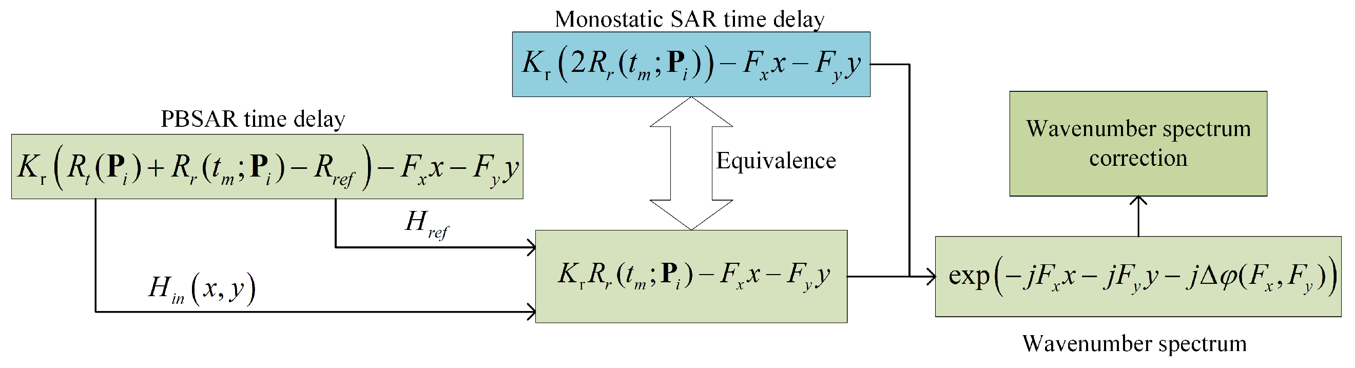

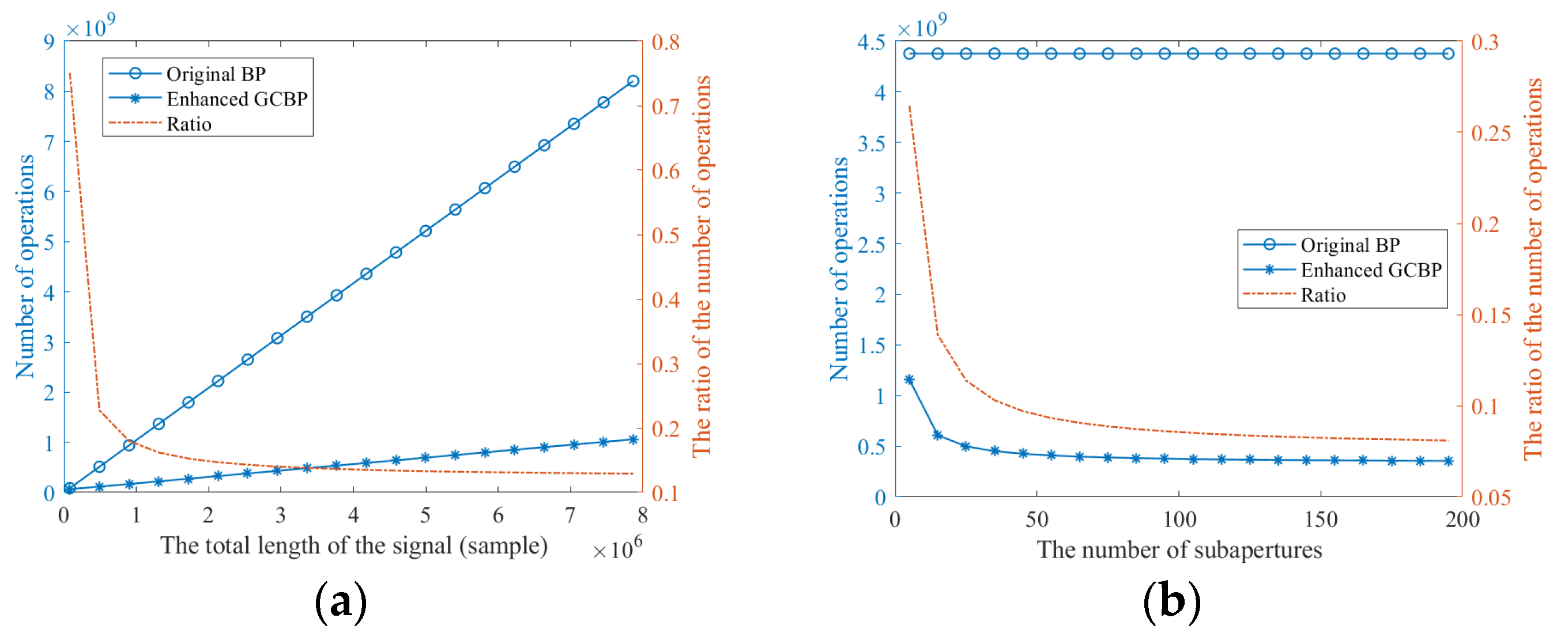
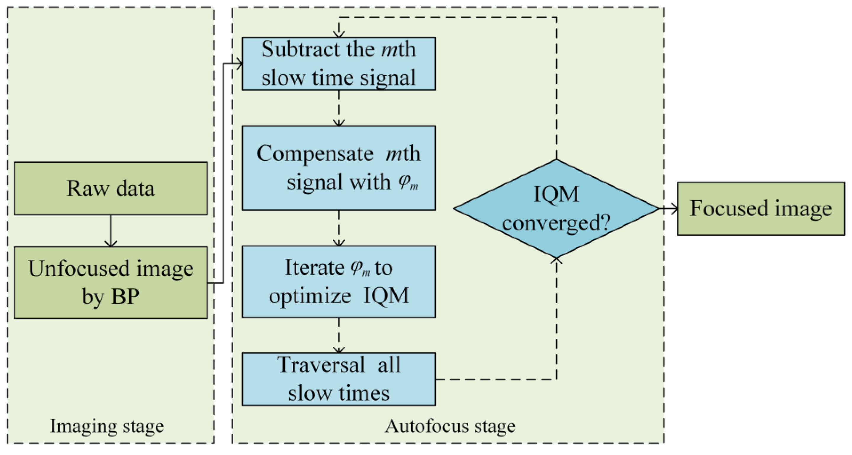
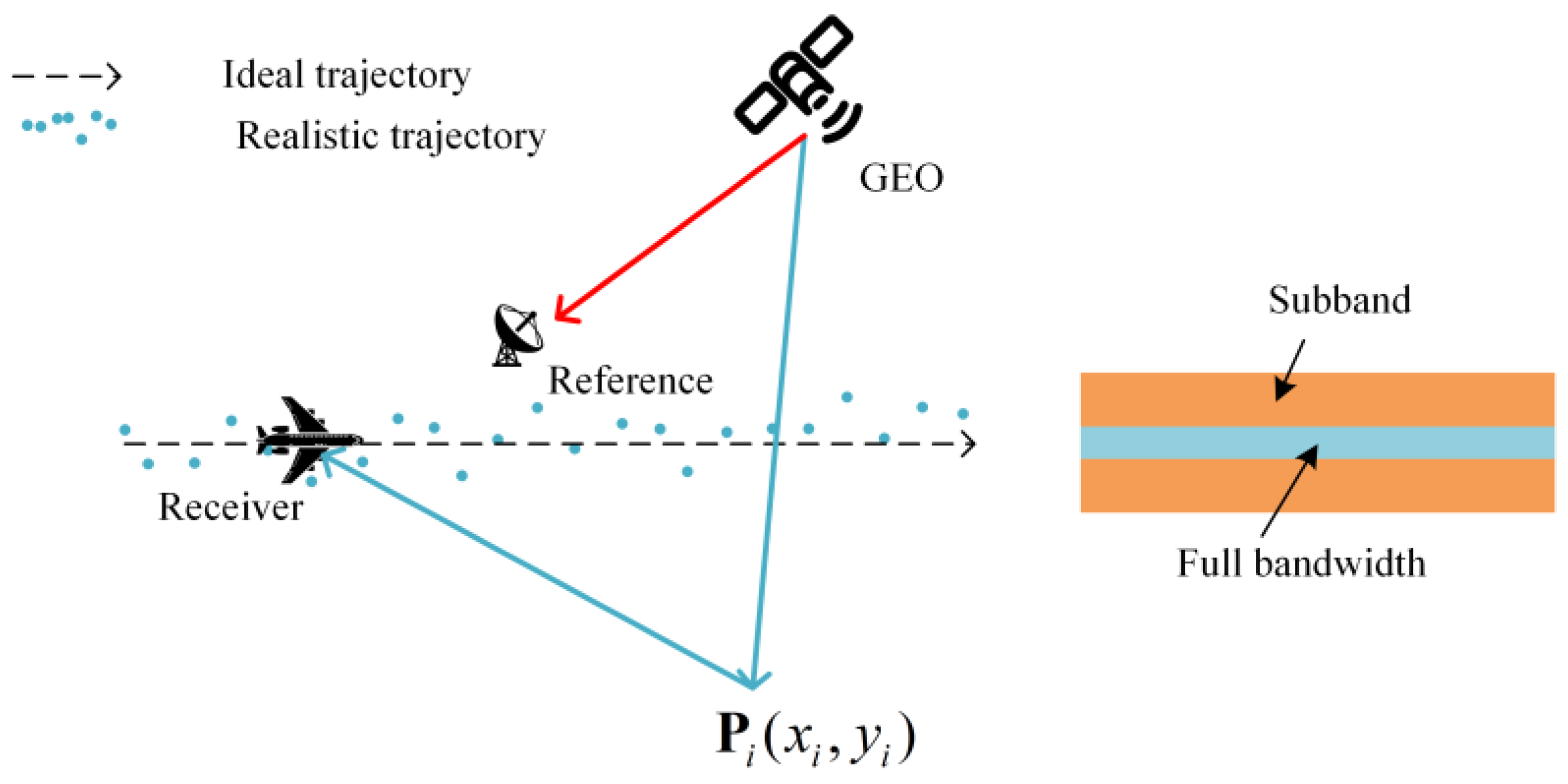

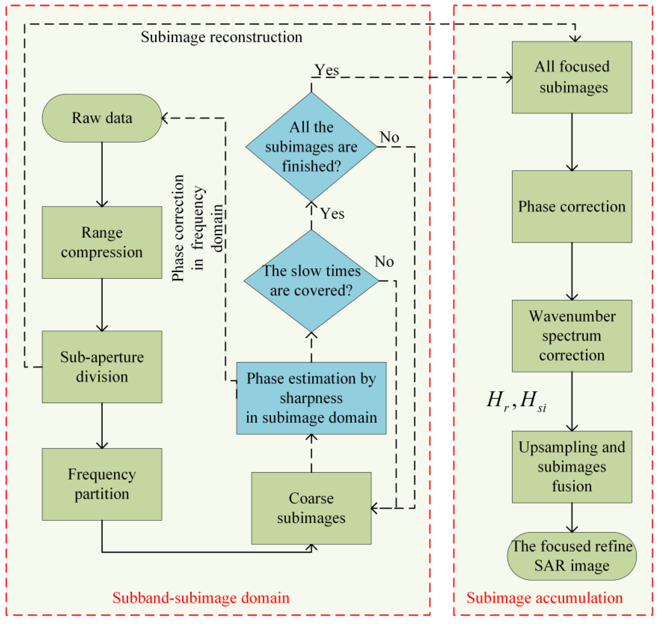


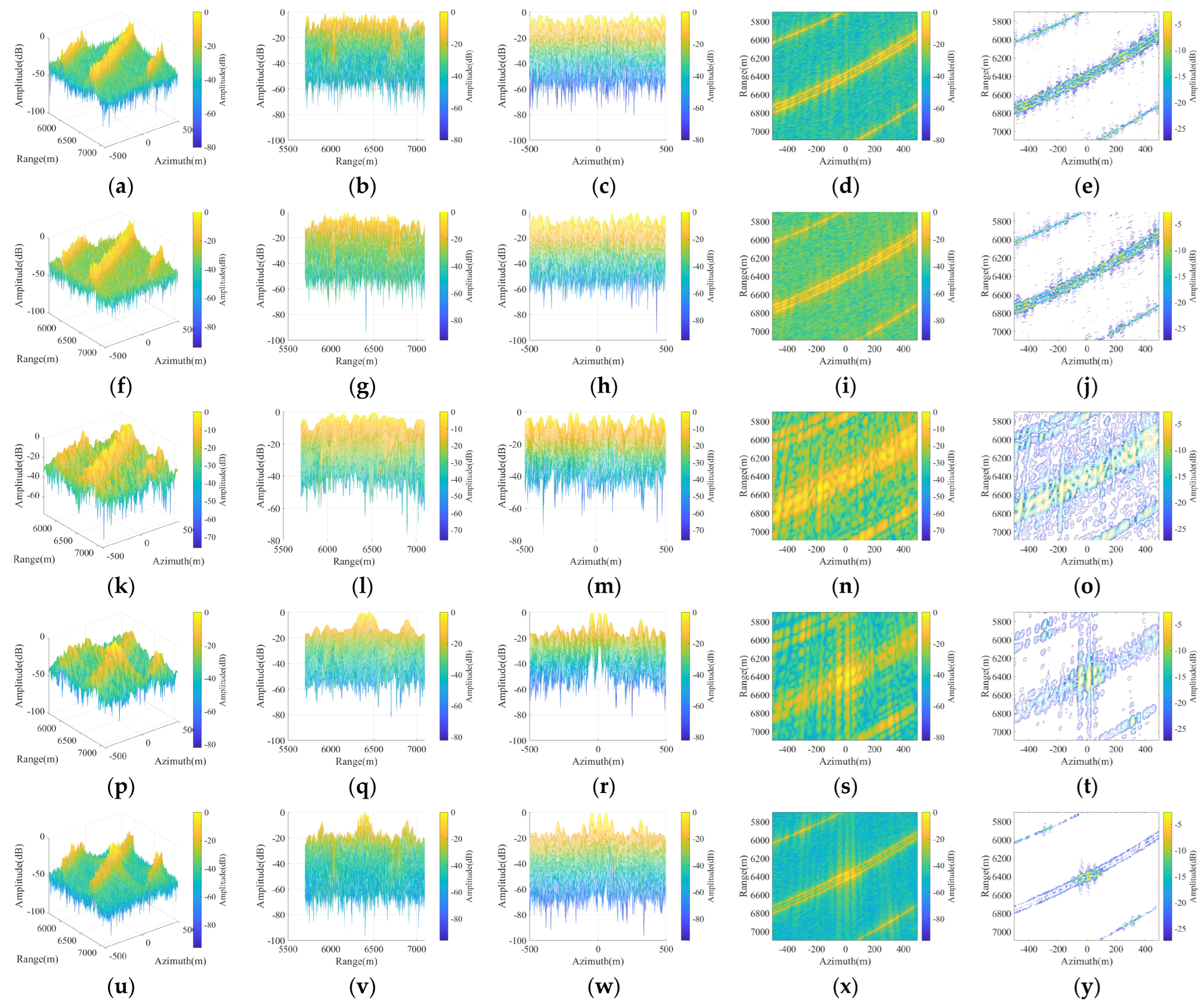
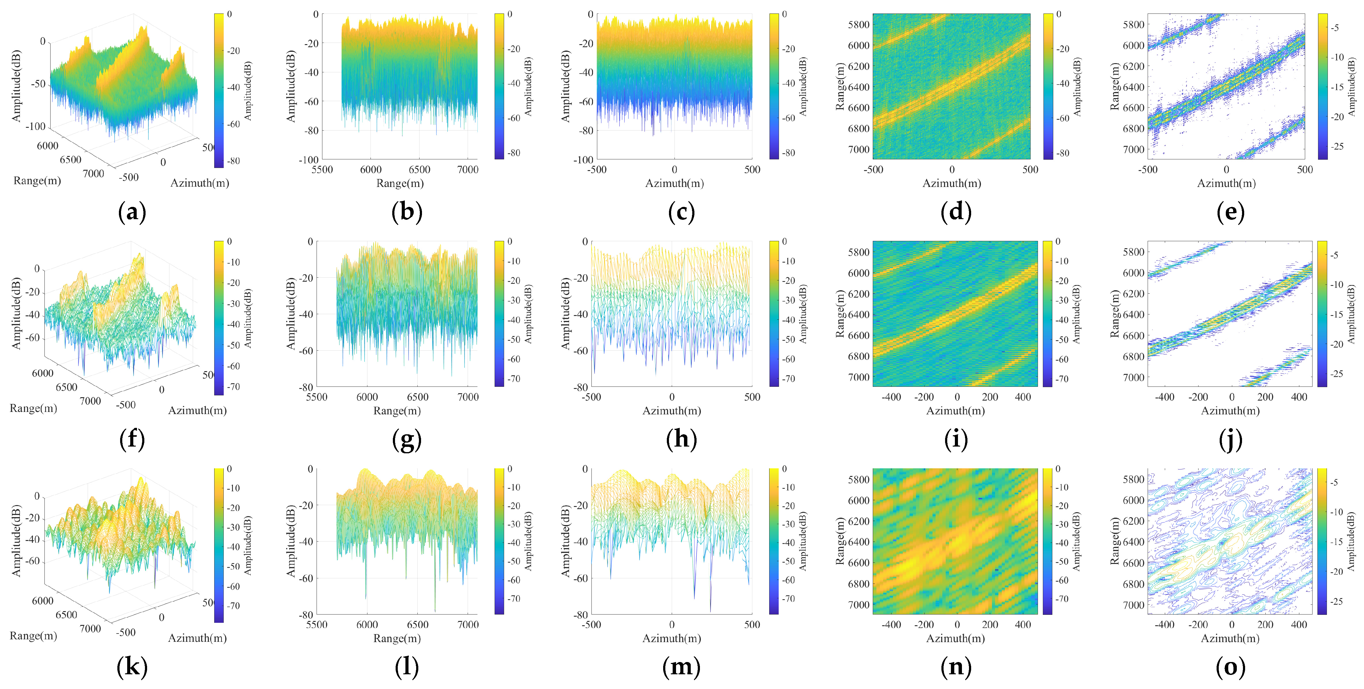


Disclaimer/Publisher’s Note: The statements, opinions and data contained in all publications are solely those of the individual author(s) and contributor(s) and not of MDPI and/or the editor(s). MDPI and/or the editor(s) disclaim responsibility for any injury to people or property resulting from any ideas, methods, instructions or products referred to in the content. |
© 2025 by the authors. Licensee MDPI, Basel, Switzerland. This article is an open access article distributed under the terms and conditions of the Creative Commons Attribution (CC BY) license (https://creativecommons.org/licenses/by/4.0/).